DMOUSC820Wireless Headphone System
Sennheiser Electronic Corp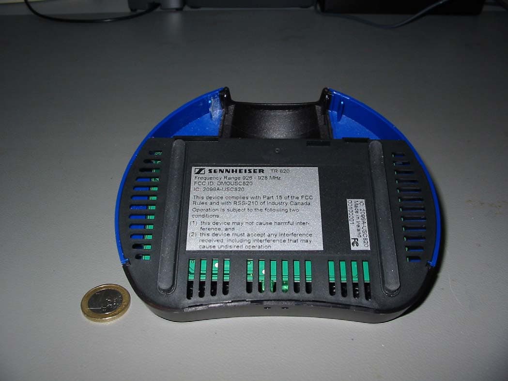
Click to zoom
Application Details
- Equipment Class
- DXX - Part 15 Low Power Communication Device Transmitter
- Date of Grant
- May 22, 2006
- Application Purpose
- Original Equipment
- Date of Application
- May 22, 2006
- Equipment Note
- Wireless Headphone System
- Frequency Range
- 926.17000000 - 926.92000000
- Company
- Sennheiser Electronic Corp
- Country
- United States
Documents & Files
Document Text
Text extracted from the exhibit documents filed with the FCC. Open a document above to read the original.
Users Manual
Statement required by FCC rules Part 15 and RSS 210 This device complies with Part 15 of the FCC Rules and with RSS-210 of Industry Canada. Operation is subjected to the fol- lowing two conditions: 1. this device may not cause harmful interference, and 2. this device must accept any interference received, including interference that may cause undesired operation. This equipment has been tested and found to comply with the limits for a Class B digital device, pursuant to Part 15 of the FCC Rules. These limits are designed to provide reasonable protec- tion against harmful interference in a residential installation. This equipment generates, uses and can radiate radio fre- quency energy and, if not installed and used in accordance with the instructions, may cause harmful interference to radio com- munications. However, there is no guarantee that interference will not occur in a particular installation. If this equipment does cause harmful interference to radio or television reception, which can be determined by turning the equipment off and on, the user is encouraged to try to correct the interference by one or more of the following measures: yReorient or relocate the receiving antenna. yIncrease the separation between the equipment and receiver. yConnect the equipment to an outlet on a circuit different from that to which the receiver is connected. yConsult the dealer or an experienced radio/TV technician for help. Warning: Changes or modifications made to this equipment not expressly approved by Sennheiser electronic GmbH & Co. KG may void the FCC authorization to operate this equipment. Sennheiser electronic GmbH & Co. KG Printed in Germany Publ. 05/06 515879 Déclaration requise par la Partie 15 des régle- mentations de la FCC et la norme RSS 210 Cet appareil est conforme à la Partie 15 des réglementations de la FCC et avec la norme RSS-210 de l'Industrie Canadienne. Son utilisation est soumise aux deux conditions suivantes : 1. il ne doit pas provoquer d'interférences gênantes et 2. il doit tolérer les interférences reçues, y compris celles susceptibles d'en perturber le fonctionnement. Cet équipement a été testé et trouvé conforme aux limites défi- nies pour un dispositif numérique de classe B, dans le cadre de la Partie 15 des réglementations de la FCC. Ces limites sont con- çues pour offrir une protection raisonnable contre les interfé- rences nocives pour une installation résidentielle. Cet équipement produit, utilise et peut émettre une énergie haute fréquence et, s'il n'est pas installé et utilisé conformément aux instructions, provoquer des interférences gênantes pour les communications radio. Des risques d'interférences ne peuvent toutefois pas être totalement exclus dans certaines installa- tions. Dans le cas d'interférences gênantes pour la réception des émissions de radio ou télédiffusées (il suffit, pour le consta- ter, d'allumer et d'éteindre l'équipement), l'utilisateur est invité à prendre l'une des mesures suivantes pour les éliminer : yRéorienter ou déplacer l'antenne réceptrice. yEloigner l'équipement du récepteur. yBrancher l'équipement sur une prise ou un circuit différent de celui du récepteur. yConsulter un revendeur ou un technicien de radio ou télévi- sion expérimenté. Avertissement : Toute modification non expressément approuvé par Sennheiser electronic GmbH & Co. KG peut annuler le droit de l'utilisateur à l'emploi de l'équipement en question. Sennheiser electronic GmbH & Co. KG Printed in Germany Publ. 05/06 515879
Users Manual
Bedienungsanleitung Instruction Manual Notice d ́emploi Instrucciones para el uso Set 820 Set 820-9_515831_0206_Sp4.book Seite 1 Mi ttwoch, 22. Februar 2006 11:23 11 Set 820-9_515831_0206_Sp4.book Seite 2 Mi ttwoch, 22. Februar 2006 11:23 11 Deutsch English Français Español Set 820-9_515831_0206_Sp4.book Seite 3 Mi ttwoch, 22. Februar 2006 11:23 11 1 Set 820Vielen Dank für den Kauf dieses Sennhe iser-Produktes. Es wird Sie viele Jahre durch Zuverlässigkeit und einfache Be dienung überzeugen. Das garantiert Sennheiser mit seinem guten Namen und seiner in mehr als 60 Jahren erwor- benen Kompetenz als Hersteller hochwe rtiger elektro-akustischer Produkte. Das Set 820 ist eine Hörhilfe, mit der Si e den Ton aus Radio, Fernseher, Ste- reoanlagen und ähnlichen Geräten bequem mit der für Sie richtigen Lautstär-ke hören können. Das Gerät erlaubt Ihnen, sich frei in einem Umkreis von bis zu 30 m um den Sender zu bewegen und dies ohne lästige Kabel. Die Ton-übertragung erfolgt mit einem Funksignal. Set 820-9_515831_0206_Sp4.book Seite 1 Mi ttwoch, 22. Februar 2006 11:23 11 2WARNUNG: Laut hören? - Nein! Mit Kopfhörern wird gern laut ge hört. Besonders, wenn Ihr gutes Gehör nachgelassen hat und Sie auf einen Höre r als Hilfe angewiesen sind, sollten Sie sich nicht ständig hoher Lautstär ke aussetzen. Schonen Sie Ihre Ohren so gut es geht. ACHTUNG: Kurzschlussgefahr Weder der Sender noch der Empfänger dü rfen nass oder üb ermässig feucht werden, z.B. durch Getränke oder bei Verwendung in Feuchträumen. Es be- steht Kurzschluss-gefahr! ACHTUNG: Die Verwendung von Komponenten ander er Hersteller (z.B. für Netzteil oder Akku) kann Schäden am Gerät verursachen und führt zum Erlöschen der Garantie! This advice complies with Part 15 of the FCC Rules and with RSS-210 of Industry Canada. Operations is sub ject to the followin g two conditions: (1) this device may not caus e harmful interference, and (2) this device must accept any interference received, indcluding interference that may cause undesired operation.FCC ID: DMOUSC820IC: 2099A-USC820 Set 820-9_515831_0206_Sp4.book Seite 2 Mi ttwoch, 22. Februar 2006 11:23 11 3 Lieferumfang Das Set 820 enthält folgende Teile:- Hörer RR 820 - Sender (Ladestation) TR 820 - Akku BA 151 - Steckernetzteil NT 820 - Anschlusskabel für Kopfhörerausgang - Adapter für CINCH-Buchse- Mikrofon MKE 800 TV - Ersatzohrpolster- Bedienungsanleitung- Quick Instructions Set 820-9_515831_0206_Sp4.book Seite 3 Mi ttwoch, 22. Februar 2006 11:23 11 4Sender (Ladestation) anschließenDer Sender verfügt auf der Rückseite über 2 Audioeingänge: Eine Buchse (LINE)zum Anschluss an die Kopfhö-rer- oder LINE OUT-Buchse des Fern-sehers und eine Mikrofonbuchse (MIC). Stecken Sie das Anschlusskabel in di e Kopfhörerbuchse oder mit dem Adap- ter in die LINE OUT-Buchse am Fernseher und in die LINE-Buchse auf der Rück- seite des Senders. Sollte Ihr Fernseher nicht über die ge nannten Anschlüsse verfügen, können Sie ein externes Mikrofon verwenden, das im Abschnitt „Zubehör“ beschrie- ben ist. Belegen Sie jeweils nur einen Eingang am Sender (MIC oder LINE). Set 820-9_515831_0206_Sp4.book Seite 4 Mi ttwoch, 22. Februar 2006 11:23 11 5 Verbinden Sie das Kabel des Netzteil s mit der POWER-Buchse am Sender. Stecken Sie das Steckernetzteil in eine zugelassene Wandsteckdose. Wenn Sie das Gerät längere Zeit nicht be nutzen, z.B. im Urla ub, ziehen Sie das Steckernetzteil aus der Wandsteckdose. Hören überall im HausSender und Kopfhörer müssen sich nicht im gleichen Raum befinden. So können Sie sich frei in Haus und Garten bewegen. Sie kön-nen mehrere Kopfhörer gleichzeitig mit ei- nem Sender betreiben. Die Reichweite des Senders kann durch die Beschaffenheit der Wände beeinträchtigt werden. Set 820-9_515831_0206_Sp4.book Seite 5 Mi ttwoch, 22. Februar 2006 11:23 11 6Aufstellort des SendersStellen Sie den Sender in die Nähe Ihrer HiFi-Anlage oder des Fernse-hers, z.B. daneben oder darauf.Stellen Sie das Gerät nicht in unmit-telbare Nähe von Metallregalen, Stahlbetonwänden oder anderen Metallkonstruktionen.Der Sender ist mit einer komforta-blen Einschaltautomatik ausgestat-tet. Ein Tonsignal schaltet den Sender ei n. Der Sender schalt et sich aus, wenn er länger als 3 Minuten kein Tonsig nal empfängt. In diesem Ruhezustand („stand by“) verbraucht der Sender nu r sehr wenig Strom und kann am Netz angeschlossen bleiben. Der Akku-Ladevorgang im Sender wird dadurch nicht beeinflusst Set 820-9_515831_0206_Sp4.book Seite 6 Mi ttwoch, 22. Februar 2006 11:23 11 7 Akku ladenStellen Sie den Hörer zum Laden des Akkus mit dem Bedienrad nach vo rn in die Ladeschale des Senders. Achten Si e darauf, dass das linke grüne Lämpchen am Sender leuchtet.Laden Sie den Akku vo r dem ersten Betrieb 24 Stunden. Danach reichen 4-5 Stunden Lade-zeit, um den Akku zu laden. Dann ist er für ca. 4 Stunden betriebsbereit.Bewahren Sie den Hörer immer im Sender auf, so erreichen Sie den besten Ladezustand. Die Ladeautomatik verhindert eine Überladung des Akkus. Der Akku kann beliebig lange in der Ladeschale de s Senders bleiben. Set 820-9_515831_0206_Sp4.book Seite 7 Mi ttwoch, 22. Februar 2006 11:23 11 8Hörer benutzen Setzen Sie den Hörer auf. Dabei muss das Bedienrad nach unten und die Schrift nach vorne zeigen.Der Hörer schaltet sich beim Aufsetzen automatisch ein, wenn Sie den Kinn-bügel spreizen.Nach Gebrauch schaltet sich der Emp-fänger automati sch wieder aus. Set 820-9_515831_0206_Sp4.book Seite 8 Mi ttwoch, 22. Februar 2006 11:23 11 9 Lautstärke einstellenDie Lautstärke des Hörers regeln Sie mit dem Bedienrad am Hörer. Bewahren Sie den Hörer in der Lademulde des Senders auf, wenn Sie ihn nicht benutzen, damit der Akku wieder aufgeladen wird. Siehe hierzu Abschnitt „Akku laden“. Set 820-9_515831_0206_Sp4.book Seite 9 Mi ttwoch, 22. Februar 2006 11:23 11 10Sendekanal wechseln Sie können Empfangsstörungen, die beim gleichzeitigen Betrieb mehrerer Sender entstehen, vermeiden, indem Sie den Sendekanal ände rn (CHANNEL). Aus zulassungstechnischen…
Text truncated - open the document above for the full version.
Cover Letter(s)
CONFIDENTIALITY REQUEST Federal Communication Commission Equipment Authorization Division, Application Processing Branch 7435 Oakland Mills Road Columbia, MD 21048 March 20, 2006 TO WHOM IT MAY CONCERN Pursuant to Paragraphs §0.457 and 0.459 of the Commission’s Rules (47 C.F.R.) and Section §552(b)(4) of the Freedom of Information Act, Company requests confidentiality for the following products: FCC ID Number Product Title/Model DMOUSC820 SET 820-9 (incl. TR820-9, RR820-9) SET 820S-9 (incl. TR820-9, RR820S-9) For the product stated above, we request that the following information be held confidential: 1. Circuit diagrams, BOM, and PCBs submitted as Equipment Authorization Electronic Filing attachment: "schematics”. 2. Block diagram submitted as Equipment Authorization Electronic Filing attachment: “blockdiagram”. 3. Operational description submitted as Equipment Authorization Electronic Filing attachment: “operational description” The above exhibits contain Company trade secrets and proprietary information that could be of benefit to our competitors regarding the design of our mobile handset. This material is not customarily available to the general public and we request that it be withheld from public inspection. If you have any questions, please feel free to contact me at the address shown below. Sincerely, Name: Volker Bartsch Company: Sennheiser electronic Address: Am Labor 1 D-30900 Wedemark (Germany) Phone: 49-5130-600-465 Email: [email protected]
External Photos
CETECOM ICT Services GmbH Untertürkheimer Str. 6-10, 66117 Saarbruecken Phone: +49 (0) 681 598-0 Fax: -9075 RSC-Laboratory Phone: +49 (0) 681 598-0 Fax: -9075 Test report no.: 2-4280-01-01/06 Date: 2006-03-24 Page 31 of 43 6 Annex C: External Photographs of the Equipment Photo 1: TR820 CETECOM ICT Services GmbH Untertürkheimer Str. 6-10, 66117 Saarbruecken Phone: +49 (0) 681 598-0 Fax: -9075 RSC-Laboratory Phone: +49 (0) 681 598-0 Fax: -9075 Test report no.: 2-4280-01-01/06 Date: 2006-03-24 Page 32 of 43 Photo 2:
ID Label/Location Info
CETECOM ICT Services GmbH Untertürkheimer Str. 6-10, 66117 Saarbruecken Phone: +49 (0) 681 598-0 Fax: -9075 RSC-Laboratory Phone: +49 (0) 681 598-0 Fax: -9075 Test report no.: 2-4280-01-01/06 Date: 2006-03-24 Page 32 of 43 Photo 2:
Internal Photos
CETECOM ICT Services GmbH Untertürkheimer Str. 6-10, 66117 Saarbruecken Phone: +49 (0) 681 598-0 Fax: -9075 RSC-Laboratory Phone: +49 (0) 681 598-0 Fax: -9075 Test report no.: 2-4280-01-01/06 Date: 2006-03-24 Page 38 of 43 7 Annex D: INTERNAL PHOTOGRAPHS OF THE EQUIPMENT Photo 1: TR820 CETECOM ICT Services GmbH Untertürkheimer Str. 6-10, 66117 Saarbruecken Phone: +49 (0) 681 598-0 Fax: -9075 RSC-Laboratory Phone: +49 (0) 681 598-0 Fax: -9075 Test report no.: 2-4280-01-01/06 Date: 2006-03-24 Page 39 of 43 Photo 2:
Test Report
CETECOM ICT Services GmbH Untertürkheimer Str. 6-10, 66117 Saarbruecken Phone: +49 (0) 681 598-0 Fax: -9075 RSC-Laboratory Phone: +49 (0) 681 598-0 Fax: -9075 Test report no.: 2-4280-01-01/06 Date: 2006-03-24 Page 1 of 43 Recognized by the Federal Communications Commission Anechoic chamber registration no.: 90462 (FCC) Anechoic chamber registration no.: 3463 (IC) TCB ID: DE 0001 Accredited by the German Accreditation Council DAR–Registration Number DAT-P-176/94-D1 Independent ETSI compliance test house ETSI Accredited Bluetooth ® Test Facility (BQTF) Test report no. : 2-4280-01-01/06 Applicant : Sennheiser electronic GmbH & Co. KG Type : SET 820(S)-9 Test Standard : FCC Part 15 / RSS210 FCC ID : DMOUSC820 Certification No. IC : 2099A-USC820 The Bluetooth word mark and logos are owned by the Bluetooth SIG, Inc. and any use of such marks by Cetecom ICT is under license. CETECOM ICT Services GmbH Untertürkheimer Str. 6-10, 66117 Saarbruecken Phone: +49 (0) 681 598-0 Fax: -9075 RSC-Laboratory Phone: +49 (0) 681 598-0 Fax: -9075 Test report no.: 2-4280-01-01/06 Date: 2006-03-24 Page 2 of 43 Table of contents 1 GENERAL INFORMATION ................................................................................................................................... 3 1.1. ADMINISTRATIVE DATA OF THE TEST FACILITY..................................................................................................... 3 1.1.1 Identification of the testing laboratory ......................................................................................................... 3 1.2. NOTES................................................................................................................................................................... 3 1.3 DETAILS OF APPLICANT......................................................................................................................................... 4 1.4 APPLICATION DETAILS.......................................................................................................................................... 4 1.5 TEST ITEM............................................................................................................................................................. 5 1.6 TEST SETUP........................................................................................................................................................... 6 1.7 TEST SPECIFICATIONS............................................................................................................................................ 6 2 STATEMENT OF COMPLIANCE .......................................................................................................................... 7 2.1 SUMMARY OF MEASUREMENT RESULTS................................................................................................................ 7 2.1.1 CFR 47 Part 15 Radio frequency devices ..................................................................................................... 7 3 MEASUREMENTS AND RESULTS ....................................................................................................................... 8 4 FCC PART 15 SUBPART B ...................................................................................................................................... 9 4.1 Timing of the transmitter .................................................................................................................................. 9 4.2 Field Strength of the Fundamental ................................................................................................................. 10 4.3 Field Strength of the Harmonics and Spurious............................................................................................... 11 4.4 Receiver Spurious Emission (radiated)........................................................................................................... 14 4.5 Conducted Limits ............................................................................................................................................ 16 4.6 Emission / Occupied Bandwidth ..................................................................................................................... 18 5 ANNEX B: PHOTOGRAPHS OF TEST SITE ..................................................................................................... 23 6 ANNEX C: EXTERNAL PHOTOGRAPHS OF THE EQUIPMENT ................................................................ 31 7 ANNEX D: INTERNAL PHOTOGRAPHS OF THE EQUIPMENT.................................................................. 38 CETECOM ICT Services GmbH Untertürkheimer Str. 6-10, 66117 Saarbruecken Phone: +49 (0) 681 598-0 Fax: -9075 RSC-Laboratory Phone: +49 (0) 681 598-0 Fax: -9075 Test report no.: 2-4280-01-01/06 Date: 2006-03-24 Page 3 of 43 1 General information 1.1. Administrative data of the test facility 1.1.1 Identification of the testing laboratory Company name: Cetecom ICT Services GmbH Address: Untertürkheimerstr. 6-10 D-66117 Saarbruecken Germany Laboratory accreditation: DAR-Registration No. DAT-P-176/94-D1 Bluetooth Qualification Test Facility (BQTF) Federal Communications Commission (FCC) Identification/Registration No : 90462 Responsible for testing laboratory: Michael Berg / Dirk Hausknecht Phone: +49 681 598 0 Fax: +49 681 598 9075 email: [email protected] 1.2. Notes The test results of this test report relate exclusively to the test item specified in 1.5. The CETECOM ICT Services GmbH does not assume responsibility for any conclusions and generalizations drawn from the test results with regard to other specimens or samples of the type of the equipment represented by the test item. The test report may only be reproduced or published in full. Reproduction or publication of extracts from the report requires the prior written approval of the CETECOM ICT Services GmbH. .................................................…
Text truncated - open the document above for the full version.
Test Setup Photos
CETECOM ICT Services GmbH Untertürkheimer Str. 6-10, 66117 Saarbruecken Phone: +49 (0) 681 598-0 Fax: -9075 RSC-Laboratory Phone: +49 (0) 681 598-0 Fax: -9075 Test report no.: 2-4280-01-01/06 Date: 2006-03-24 Page 23 of 43 5 Annex B: Photographs of Test site Photo 1 (Radiated Emissions): TR820 CETECOM ICT Services GmbH Untertürkheimer Str. 6-10, 66117 Saarbruecken Phone: +49 (0) 681 598-0 Fax: -9075 RSC-Laboratory Phone: +49 (0) 681 598-0 Fax: -9075 Test report no.: 2-4280-01-01/06 Date: 2006-03-24 Page 24 of 43 Photo 2 (Radiated Emissions): TR820
Contact Information
Applicant
Michael Lieske
Test Firm
cetecom advanced GmbHGerald Schmidt
Technical Specifications
| # | Rule Parts | Frequency Range | Power Output |
|---|---|---|---|
| 1 | 15C | 926.17 MHz - 926.92 MHz | - |
Other Applications from Sennheiser Electronic Corp
DMOSKM1G4
Aug 19, 2026Handheld Transmitter
Equipment Class
TLD - Licensed LPAS DeviceDMOSKMUHF
May 20, 2026Antenna Transceiver
Equipment Class
DWM - Part 15 Wireless Microphone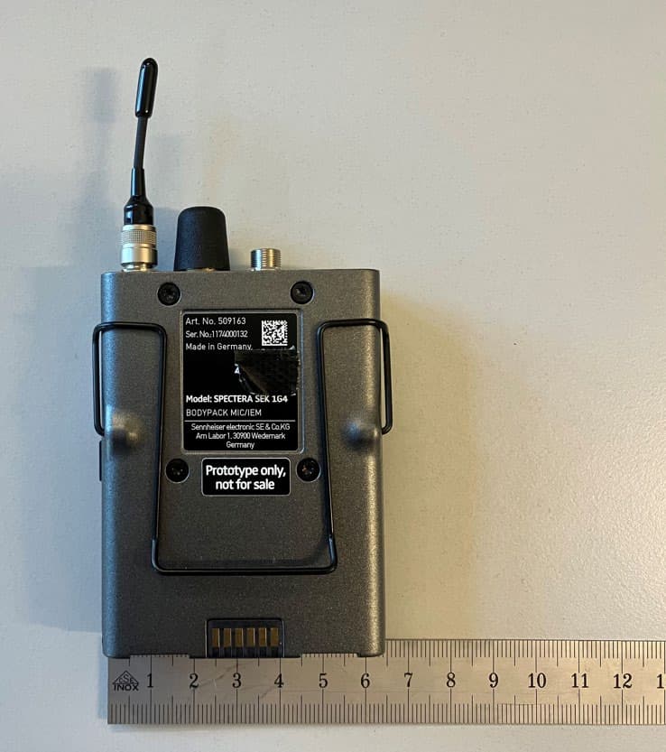
DMOSEK1G4
Mar 11, 2026Bodypack Mic/IEM
Equipment Class
TLD - Licensed LPAS Device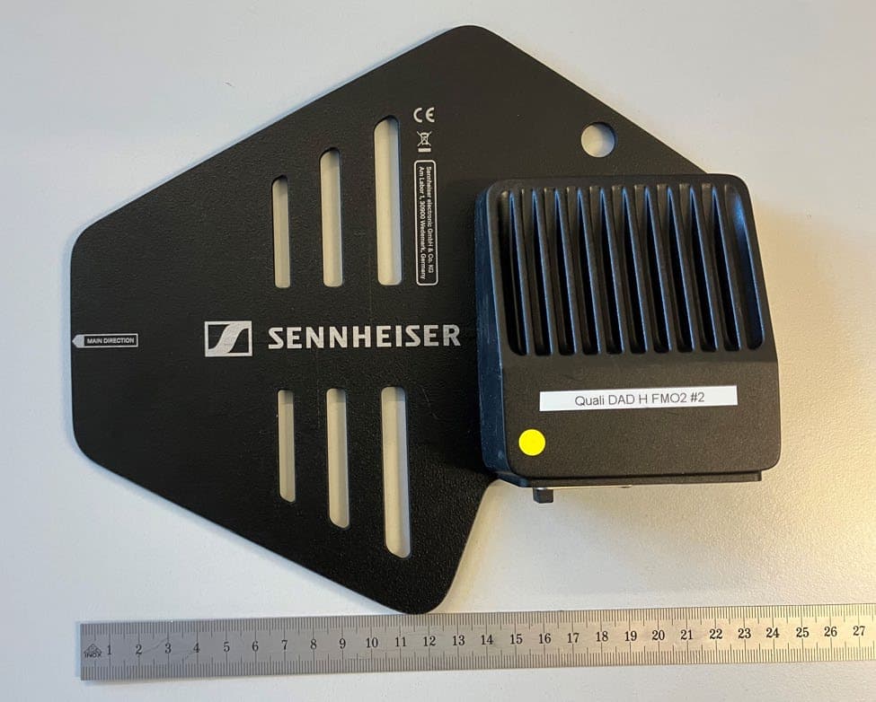
DMODAD1G4
Mar 11, 2026Antenna Transceiver
Equipment Class
TLD - Licensed LPAS DeviceDMOTSEWDX
Jan 30, 2024Wireless Table Stand
Equipment Class
TLD - Licensed LPAS Device