DVE-EBIOTPCWMRadio Module (not sold separately, part of the selected commercial products)
Schneider Electric Buildings LLC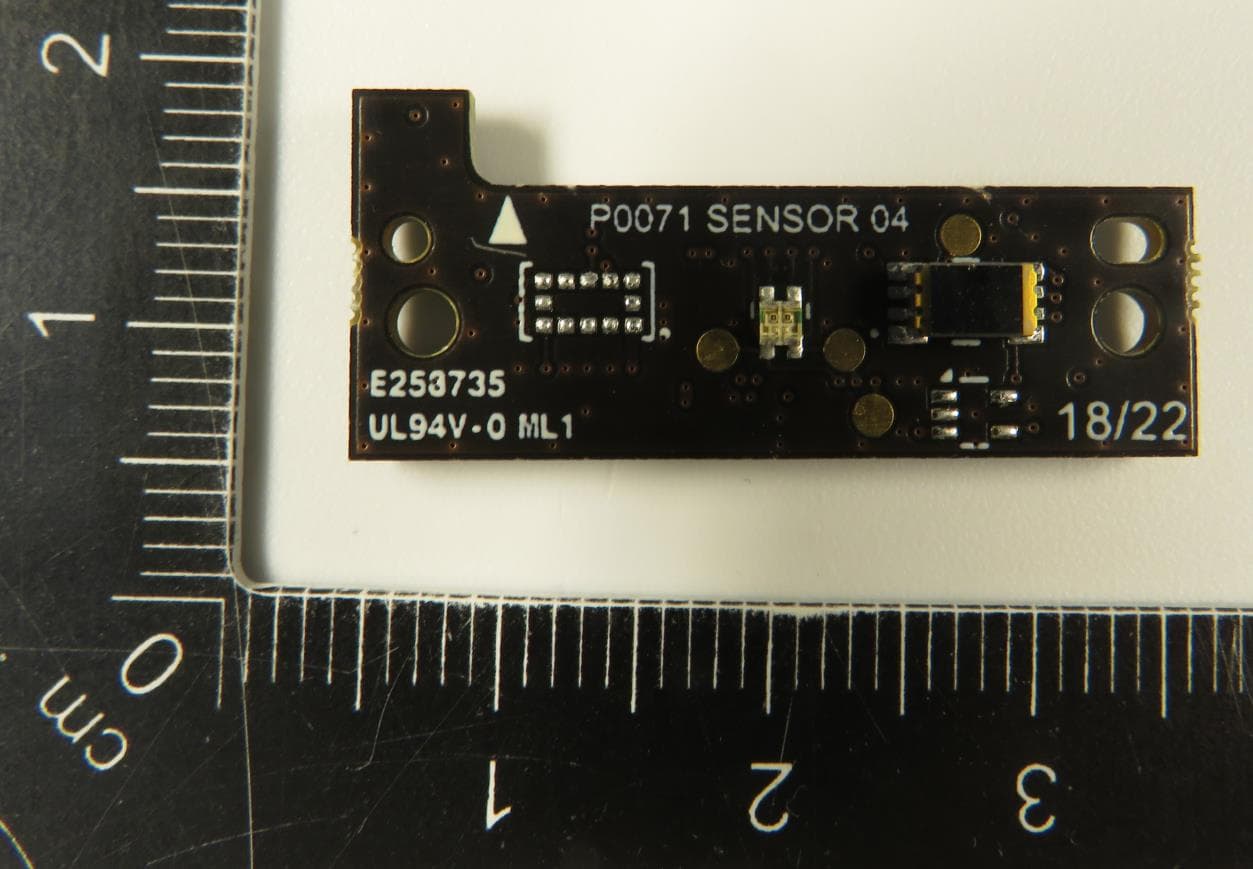
Click to zoom
Application Details
- Equipment Class
- DTS - Digital Transmission System
- Date of Grant
- Dec 13, 2022
- Application Purpose
- Original Equipment
- Date of Application
- Dec 13, 2022
- Equipment Note
- Radio Module (not sold separately, part of the selected commercial products)
- Frequency Range
- 2402.00000000 - 2480.00000000
- Country
- United States
Documents & Files
Document Text
Text extracted from the exhibit documents filed with the FCC. Open a document above to read the original.
Users Manual
© Schneider Electric Buildings LLC (Authored by Treon Oy for Schneider Electric) P a g e 1 | 9 EBIOTPCWM User Manual Version 1.1 Date Version Editor Status Notes 21.10.2022 0.1 Tuomo Nikkilä Draft Initial draft created, Electronics information added 25.10.2022 0.2 Timo Yli-Pietilä Draft Integration guidelines and labelling chapter added 26.10.2022 0.3 Ella Raitio Draft Label and compliance information added 1.11.2022 0.4 Ella Raitio Draft Certification information added 15.11.2022 0.5 Ella Raitio Draft Updated labelling instructions added 17.11.2022 1.0 Version 2.12.2022 1.1 Version FCC and ISED statements added © Schneider Electric Buildings LLC (Authored by Treon Oy for Schneider Electric) P a g e 2 | 9 Contents Acronyms and abbreviations .................................................................................................................. 3 1 Introduction .................................................................................................................................... 4 1.1 General .................................................................................................................................... 4 1.2 Certification information ........................................................................................................ 4 1.3 Functions ................................................................................................................................. 4 2 Operating conditions ...................................................................................................................... 5 3 Integration instructions for host product manufacturers .............................................................. 5 3.1 List of applicable FCC / ISED rules ........................................................................................... 5 3.2 Specific operational use conditions ........................................................................................ 5 3.3 Limited module procedures .................................................................................................... 5 3.4 Trace antenna designs ............................................................................................................ 5 3.5 RF exposure considerations .................................................................................................... 5 3.6 Antennas ................................................................................................................................. 6 3.7 Information on test modes and additional testing requirements .......................................... 6 3.8 Additional testing, Part 15 Subpart B disclaimer .................................................................... 6 4 Label and compliance information ................................................................................................. 6 4.1 Labelling instructions .............................................................................................................. 7 5 FCC and ISED statements ................................................................................................................ 9 © Schneider Electric Buildings LLC (Authored by Treon Oy for Schneider Electric) P a g e 3 | 9 Acronyms and abbreviations EMC Electromagnetic Compatibility SoC System on Chip IC Integrated Circuit PMN Product Marketing Name HVIN Hardware Version Identification Number © Schneider Electric Buildings LLC (Authored by Treon Oy for Schneider Electric) P a g e 4 | 9 1 Introduction 1.1 General EBIOTPCWM (also referred to as ,,TR Module’’ to increase the readability of this document) is a BLE/Wirepas 2.4GHz radio module. In general, TR Module includes full 2.4 GHz radio functionality in- cluding radio SoC (System on Chip), power supply, crystals, antenna, and interface for variety of sensor modules. TR Module is not sold separately, it is part of selected commercial products. 1.2 Certification information The certification related information and naming of the EBIOTPCWM can be found below. PMN: EBIOTPCWM HVIN: EBIOTPCWM FCC ID: DVE-EBIOTPCWM IC ID: 24775-EBIOTPCWM EBIOTPCWM will be used as a radio module inside selected Sensor Solutions for Building-IoT. 1.3 Functions TR Module has two functions. It communicates to network using 2.4GHz ISM band and it has a board- to-board connector that can be used to connect to different peripheral PCBs. It also has an integrated PCB antenna and STSAFA security chip. © Schneider Electric Buildings LLC (Authored by Treon Oy for Schneider Electric) P a g e 5 | 9 2 Operating conditions The operating conditions of EBIOTPCWM can be found in the table below. Min Max Operating voltage V 1.7 3.6 Operating temperature C 0 50 Current consumption 10uA 20mA Maximum clock frequency is 32MHz and sleep clock is 32kHz. 3 Integration instructions for host product manufacturers 3.1 List of applicable FCC / ISED rules FCC: ISED: 47 CFR Part 15 Subpart C §15.247 RSS-247, Issue 2 3.2 Specific operational use conditions To keep the antenna performance on tested level, antenna area of the TR Module is good to keep away from metal structures (10mm distance or more). Avoid attaching flexes, wires or floating metal structures directly on top of TR Module. 3.3 Limited module procedures Limited module procedure is needed because TR Module does not have a separate shield on radio SoC IC. To meet test requirements with host products, it is good practice to avoid attaching flexes, wires or floating metal structures close TR Module or it’s antenna. 3.4 Trace antenna designs TR Module contains integrated monopole PCB trace antenna. Maximum tested antenna gain is 4.8dBi. 3.5 RF exposure considerations RF Exposure Evaluation with SAR test exclusion for TR Module is available. For SAR test exclusion of 5mm separation distance was used giving results well below the limits. © Schneider Electric Buildings LLC (Authored by Treon Oy for Schneider Electric) P a g e 6 | 9 RF Exposure…
Text truncated - open the document above for the full version.
Cover Letter(s)
Federal Communications Commission Authorization and Evaluation Division Equipment Authorization Branch 7435 Oakland Mills Road Columbia, MD 21046 11/8/2022 To whom it may concern: We, the undersigned, hereby authorize Eurofins Product Service GmbH to act on our behalf in all matters relating to applications for equipment authorization FCC ID: DVE-EBIOTPCWM including the signing of all documents related to these matters. Any and all acts carried out by Eurofins Product Service GmbH on our behalf shall have the same effect as acts of our own. By signing this application form, we agree to Eurofins’ current valid General Terms and Conditions (AGB), Testing and Certification Regulations (PZO) which can be viewed on following website www.eurofins.de/ee or retrieved on request. We also hereby certify that no party to this application is subject to a denial of benefits, including FCC benefits, pursuant to Section 5301 of the Anti-Drug Abuse Act of 1988, 21 U.S.C. 862. Sincerely, Signature [Name] Joni Korppi [Title] CEO [Company] Treon Oy
Cover Letter(s)
Schneider Electric Postal address: 7262 Marconi Montreal, Qc H2R 2Z5 Tel.: 514 313-8885 www.schneider- electric.com Date: 8 November 2022 Federal Communications Commission 45 L Street NE Washington, DC 20554 United States of America Authorization Letter for: PMN : EBIOTPCWM HVIN: EBIOTPCWM FCC ID : DVE-EBIOTPCWM HMN EcoStruxure TM Building-IoT Sensor Solutions We, Schneider Electric Buildings LLC 839 North Perryville, Rockford, IL 61107 USA hereby authorize: Treon Oy Visiokatu 6, 33720 Tampere, Finland Mr. Joni Korppi Title: CEO, Treon Oy E-mail: [email protected] Phone: +358 50 5979532 to act as our agent in the preparation of this application for equipment certification, including the signing of all documents relating to these matters. The present authorization considers the development of documents on behalf of the client, written under their own letterhead and related to the necessary information to be provided on their behalf to complete the certification process. For instances, where our authorized agent signs the application for certification on our behalf, I acknowledge that all responsibility for complying with the terms and conditions for Certification, as specified by Treon Oy, still resides in our company. This agreement expires in one year from the current date. Sincerely, __________________________ By: Fredrik Goth Title: R&D, Director Company: Schneider Electric E-mail: [email protected] Phone: 438-863 4977
Cover Letter(s)
Eurofins Product Service GmbH Storkower Str. 38c 15526 Reichenwalde b. Berlin Germany Tel +49-33631-888 0 Fax +49-33631-888 650 www.eurofins.de/ipt www.eurofins.com Place of Business: Reichenwalde Registration Office: Frankfurt (Oder) HRB 13937 FF VAT no: DE257676793 Managing Director: Christian Keding Bank Details: UniCredit Bank AG IBAN: DE70 2073 0017 7000 0015 50 SWIFT BIC: HYVEDEMME17 REQUEST FOR CONFIDENTIALITY [Reference Document: FCC KDB# # 726920 D02 Confidentiality Procedures Detail v01] NOTE: If you do not require confidentiality your exhibits are visible on the FCC website for everyone. A request for confidentiality must be indicated in item 8 of the 731 form and a letter making specific request for confidentiality must accompany the application as a separate exhibit. This letter must state exactly which portions of the application are to be held in confidence and for what specific reason. Exhibit types that are commonly held confidential are: (1) schematic diagrams, (2) detailed block diagrams, (3) detailed operational descriptions, (4) parts lists, and (5) tune up procedures (if applicable). Internal photos and user's manual exhibits, while not typically held confidential, may be eligible for long confidentiality in certain circumstances. Additional justification must be provided in these cases: (6) Internal Photos (may be held confidential when i.e. - the circuit board is enclosed in epoxy or some sort of material that would destroy the circuit board if it was removed; - the device is sealed using special fasteners that cannot be opened using common hand tools or if the PCB’s are completely potted; → Provide photos justifying the attestation. → Provide justification as to how the device is sealed and how disassembly would destroy the product and circuit board. (7) Users manuals (may be held in confidence when i.e. - the manual will only be available to licensed or specially trained personnel. - the manual is very technical and is not provided to the consumer because the consumer cannot service the device → Submit an agreement such as a non-disclosure agreement, purchase agreement or installation agreement, between the grantee and the purchaser that is consistent with the submitted confidentiality request with regard to the internal photos, manual or any installation requirements such as located in an inaccessible area. The agreement should be on company's letter head. If applicable, the agreement should indicate how the purchaser will install the device and how the internal photo(s) or manual will not be given to the public The FCC is a federal agency and as such has duties to the public to disclose information made known to it (see 47 CFR 0). The FCC has a procedure to handle confidential items and any request will be delivered to the FCC for them to decide if it can be held in confidence (PBA procedure). A request for confidentially does not guarantee that the FCC will grant it. Please find below the letter for confidentiality request. Federal Communications Commission Equipment Authorization Branch 7435 Oakland Mills Road Columbia, MD 21046 11/8/2022 Request for Permanent Confidentiality Company name: Schneider Electric Buildings LLC FCC ID: DVE-EBIOTPCWM FCC Part 15 Certification Gentlemen, In accordance with CFR 47 § 0.457 and CFR 47 § 0.459 Schneider Electric Buildings LLC hereby requests confidentiality of following attachments: (1) schematic diagrams, (2) detailed block diagrams, (3) detailed operational descriptions, (4) parts lists. These documents contain detailed system and equipment description and related information about the product which Schneider Electric Buildings LLC considers to be proprietary, confidential and a custom design and otherwise would not release to the general public. Since the design is a basis from which future technological products will evolve, Schneider Electric Buildings LLC considers that this information would be of benefit to its competitors and that the disclosure of the information in these documents would give competitors an unfair advantage in the market. Sincerely, Signature [Name] Joni Korppi [Title] CEO Treon Oy Visiokatu 3 33720 Tampere, Finland
Cover Letter(s)
Provided by Eu rofins Product Service GmbH v.0. 2 Declaration concerning Antenna Specification It is hereby declared that the product Model No.: EBIOTPCWM FCC ID: DVE-EBIOTPCWM fulfills the requirement in FCC test relating to the antenna type. The device specified above confirms to the FCC recommendations for internal antenna type described below: Model No. of antenna: N/A Type of antenna: Monopole PCB trace antenna Peak Gain of the antenna: 4.8 dBi Frequency range: 2402-2483.5 MHz The mounting of the antenna is fixed to the radio module and no other antenna should be used. Company name: Schneider Electric Buildings LLC Address: 839 North Perryville City: Rockford ZIP / Postal code: 61107 IL Country: USA Place: Tampere, Finland Date: 2022-11-08 Signature: Joni Korppi CEO Treon Oy
Cover Letter(s)
Limited Modular Approval - FCC Source: § 15.212 Modular transmitters. Labelling requirements for Host device: (A) If using a permanently affixed label, the modular transmitter must be labeled with its own FCC identification number, and, if the FCC identification number is not visible when the module is installed inside another device, then the outside of the device into which the module is installed must also display a label referring to the enclosed module. This exterior label can use wording such as the following: “Contains Transmitter Module FCC ID: XYZMODEL1” or “Contains FCC ID: XYZMODEL1.” Any similar wording that expresses the same meaning may be used. The Grantee may either provide such a label, an example of which must be included in the application for equipment authorization, or, must provide adequate instructions along with the module which explain this requirement. In the latter case, a copy of these instructions must be included in the application for equipment authorization. (B) If the modular transmitter uses an electronic display of the FCC identification number, the information must be readily accessible and visible on the modular transmitter or on the device in which it is installed. If the module is installed inside another device, then the outside of the device into which the module is installed must display a label referring to the enclosed module. This exterior label can use wording such as the following: “Contains FCC certified transmitter module(s).” Any similar wording that expresses the same meaning may be used. The user manual must include instructions on how to access the electronic display. A copy of these instructions must be included in the application for equipment authorization. The modular transmitter must comply with any applicable RF exposure requirements in its final configuration. Limited Modular Approval Request Letter Date: 2022-11-08 FCC ID: DVE-EBIOTPCWM Type of Equipment: BLE/Wirepas 2.4GHz radio module This transmitter, model: EBIOTPCWM is designed by us. It complies with the modular transmitters basic requirements (Item 1 to 8) in FCC Part 15 Subpart C Section 15.212 as indicated below: Modular approval requirement Yes No i Have its own shielding X ii Have buffered modulation/data inputs x iii Have its own power supply regulation x iv Comply with the antenna and transmission system requirements of § 15.203, 15.204(b) and 15.204 x v Tested in a stand-alone configuration. Unless the transmitter module will be battery powered, it must comply with the AC line conducted requirements found in FCC § 15.207. AC or DC power lines and data input/output lines connected to the module must not contain ferrites, unless they will be marketed with the module. The length of these lines shall be the length typical of actual use or, if that length is unknown, at least 10 centimeters to insure that there is no coupling between the case of the module and supporting equipment. Any accessories, peripherals, or support equipment connected to the module during testing shall be unmodified and commercially available. x vi Equipped with either a permanently affixed label or must be capable of electronically displaying its FCC ID. If the FCC ID is not visible when the module is installed inside another device, then the outside of the device into which the module is installed must also display a label referring to the enclosed module. X Label does not fit to the module. Instead, the FCC ID is visible in the label(s) of the end-product(s) and the user manual of the module. vii Comply with any specific rules or operating requirements that ordinarily apply to a complete transmitter and the manufacturer must provide adequate instructions along with the module to explain any such requirements. x viii Comply with any applicable RF exposure requirements in its final configurations: The modular transmitter complies with FCC radiation exposure requirement. x Name Joni Korppi Title CEO Company Treon Oy Signature:
External Photos
Main PCB Top Main PCB Bottom: PCB 2 top: PCB 2 bottom:
Internal Photos
Main PCB Top Main PCB Bottom: PCB 2 top: PCB 2 bottom:
RF Exposure Info
1 (6) Copyright©Verkotan FCC RF Exposure Evaluation Report_radio module_ID5927_29112022.docx RF Exposure Evaluation Report Date of Report 29/11/2022 Client’s Contact person: Kevin McCandless Number of pages: 6 Responsible Test engineer: Jesper Varis Testing laboratory: Verkotan Oy Elektroniikkatie 17 90590 Oulu Finland Client: Schneider Electric Buildings LLC 839 North Perryville, Rockford IL 61107, USA Tested devices Radio Module Related reports: - Testing has been carried out in accordance with: 47CFR §2.1093 Radiofrequency Radiation Exposure Evaluation: Portable Devices FCC published RF exposure KDB procedures Documentation: The test report must always be reproduced in full; reproduction of an excerpt only is subject to written approval of the testing laboratory Test Results: The DUT complies with the requirements in respect of all parameters subject to the test. The test results relate only to devices specified in this document Date and signatures: 29.11.2022 For the contents: Laboratory Manager 2 (6) Copyright©Verkotan FCC RF Exposure Evaluation Report_radio module_ID5927_29112022.docx TABLE OF CONTENTS 1. SUMMARY OF SAR TEST REPORT .............................................................................................. 3 1.1 TEST DETAILS ......................................................................................................................... 3 1.2 EVALUATION RESULTS .......................................................................................................... 3 2. DESCRIPTION OF THE DEVICE UNDER TEST (DUT) ................................................................... 4 2.1 SUPPORTED FREQUENCY BANDS AND OPERATIONAL MODES ............................................ 4 3. TEST EXCLUSIONS ....................................................................................................................... 5 4. RESULTS ....................................................................................................................................... 6 4.1 MAXIMUM DEFINED OUTPUT POWER AND ERP ................................................................... 6 3 (6) Copyright©Verkotan FCC RF Exposure Evaluation Report_radio module_ID5927_29112022.docx 1. SUMMARY OF SAR TEST REPORT 1.1 Test Details Device under Test (DUT): Product: Radio Module (not sold separately, module is part of commercial products) Manufacturer: Treon Oy Model: EBIOTPCWM Hardware Version: Main_07 FCC ID: DVE-EBIOTPCWM FCC Test Firm Designation Number: FI0005 Document ID: FCC RF Exposure Evaluation Report_radio module_ID5927_29112022.docx Document History/changes This report replaces FCC SAR test report_radio module_ID5927_28112022. Title of the report changed. 1.2 Evaluation Results The device conforms to the requirements of the standards when the maximum output power is less than or equal to the Test Exclusion Threshold Limit. * According to Appendix A at 447498D04 Interim General RF Exposure Guidance, the equation (B.2.) defines the thresholds for available maximum time-averaged power or maximum time-averaged ERP, whichever is greater. Regulator System Test Exclusion Threshold Limit at 5 mm separation [mW] Maximum Power* [mW] Result FCC Wirepas 2.7 0.41 PASS 4 (6) Copyright©Verkotan FCC RF Exposure Evaluation Report_radio module_ID5927_29112022.docx 2. DESCRIPTION OF THE DEVICE UNDER TEST (DUT) The DUT is a stand-alone module that includes full 2.4GHz radio functionality including radio SOC (System on Chip), power supply, crystals, PCB antenna, and interface for variety of sensor modules. A Product family is created around the DUT. It not sold separately, only as a part of commercial products According to measurement report “Antenna report for TR Module with Desk and IAQ sensors”, maximum antenna gain is 4.8 dBm. Exposure Environment General population, uncontrolled 2.1 Supported Frequency Bands and Operational Modes TX Frequency bands Modes of Operation Transmitter Frequency Range (MHz) Wirepas 2400 – 2483.5 5 (6) Copyright©Verkotan FCC RF Exposure Evaluation Report_radio module_ID5927_29112022.docx 3. TEST EXCLUSIONS FCC SAR test exclusion threshold is calculated according to 447498D04 Interim General RF Exposure Guidance, equation B.2 and B.1: 푃푡ℎ ( 푚푊 ) = { 퐸푅푃 20 푐푚 ( 푑∕20푐푚 ) 푥 푑≤20푐푚 퐸푅푃 20 푐푚 20푐푚<푑≤40푐푚 (Equation 1) where 푥=−log 10 ( 60 퐸푅푃 20 푐푚 √ 푓 ) (Equation 2) and f is in GHz, d is the separation distance (cm), and ERP20cm is per Equation 3 (B.1) below. 퐸푅푃20푐푚 ( 푚푊 ) = { 2040푓 0.3≤푓<1.5퐺퐻푧 3060 1.5퐺퐻푧≤푓≤6퐺퐻푧 (Equation 3) Transmission mode Frequency (f) Separation distance (d) P th [mW] Wirepas 2.48 GHz 0.5 2.7 6 (6) Copyright©Verkotan FCC RF Exposure Evaluation Report_radio module_ID5927_29112022.docx 4. RESULTS 4.1 Maximum defined Output Power and ERP According to Appendix A at 447498D04 Interim General RF Exposure Guidance, the equation (B.2.) defines the thresholds for available maximum time-averaged power or maximum time-averaged ERP, whichever is greater. According to the manufacturer maximum TX output power is 8mW and the duty cycle of the transmission is 2.8%: 8mW * 0.028 = 0.22 mW. Since the ERP is greater than the maximum output power, it is used for SAR test exclusion. Transmission mode Output power [dBm] Output power [mW] Power Gain of Antenna, G [dBi] EIRP Output power [dBm] ERP Output power [dBm] ERP Output power [mW] P th [mW] Wirepas -6.5 0.22 4.8 -1.69 -3.84 0.41 2.7 The ERP of the DUT is below the test exclusion threshold.
Test Report
Test Report No.: G0M-2205-1448-TFC247BL-V03 Eurofins Product Service GmbH Storkower Str. 38c, D-15526 Reichenwalde, Germany Page 1 of 86 RADIO REPORT FCC 47 CFR Part 15C ISED Canada RSS-247 Digital transmission systems operating within the 2400.0 MHz - 2483.5 MHz band Report Reference No G0M-2205-1448-TFC247BL-V03 Testing Laboratory Eurofins Product Service GmbH Address Storkower Str. 38c 15526 Reichenwalde Germany Accreditation DAkkS - Registration number : D-PL-12092-01-03 (ISED) ISED Testing Laboratory site: 3470A DAkkS - Registration number : D-PL-12092-01-04 (FCC) FCC Filed Test Laboratory, Reg.-No.: 96970 Applicant Schneider Electric Buildings LLC Address 839 North Perryville IL 61107 Rockford USA Test Specification 47 CFR Part 15C RSS-247, Issue 2, 2017-02 RSS-Gen, Issue 5, Amendment 2, 2021-02 Non-Standard Test Method None Equipment under Test (EUT): Product Description Radio Module (not sold separately, module is part of the commercial products) Model(s) EBIOTPCWM Additional Model(s) None Brand Name(s) None Hardware Version(s) P0070 Main_07 Software Version(s) nRF SDK v1.9.1 FCC ID DVE-EBIOTPCWM IC 24775-EBIOTPCWM Test Result PASSED Test Report No.: G0M-2205-1448-TFC247BL-V03 Eurofins Product Service GmbH Storkower Str. 38c, D-15526 Reichenwalde, Germany Page 3 of 86 VERSION HISTORY Version History Version Issue Date Remarks Revised By 01 2022-11-17 Initial Release 02 2022-11-29 Replaced document: G0M-2205-1448-TFC247BL-V01 Replaced by: G0M-2205-1448-TFC247BL-V02 Reason: - Product Description changed - Setup photos added in section 3.8 O. Qawasmeh 03 2022-12-08 Replaced document: G0M-2205-1448-TFC247BL-V02 Replaced by: G0M-2205-1448-TFC247BL-V03 Reason: - HMN removed Dr.-Ing. Dhamia Almozani Test Report No.: G0M-2205-1448-TFC247BL-V03 Eurofins Product Service GmbH Storkower Str. 38c, D-15526 Reichenwalde, Germany Page 4 of 86 ABBREVIATIONS AND ACRONYMS Acronyms Acronym Description EUT Equipment Under Test FCC Federal Communications Commission ISED Innovation, Science and Economic Development Canada RBW Resolution bandwidth RMS Root mean square VBW Video bandwidth V NOM Nominal supply voltage Test Report No.: G0M-2205-1448-TFC247BL-V03 Eurofins Product Service GmbH Storkower Str. 38c, D-15526 Reichenwalde, Germany Page 5 of 86 REPORT INDEX 1 Equipment (Test Item) Under Test................................................................................................... 6 1.1 Photos – Equipment External ........................................................................................................................ 7 1.2 Photos – Equipment Internal ....................................................................................................................... 10 1.3 Support Equipment ...................................................................................................................................... 12 1.4 Test Modes ................................................................................................................................................. 13 1.5 Test Frequencies ......................................................................................................................................... 14 1.6 Sample emission level calculation ............................................................................................................... 15 2 Result Summary ............................................................................................................................... 16 3 Test Conditions and Results .......................................................................................................... 17 3.1 Test Conditions and Results - Occupied bandwidth .................................................................................... 17 3.2 Test Conditions and Results - 6 dB bandwidth ............................................................................................ 21 3.3 Test Conditions and Results - Maximum peak conducted output power ..................................................... 26 3.4 Test Conditions and Results - Power spectral density ................................................................................ 31 3.5 Test Conditions and Results - AC powerline conducted emissions ............................................................. 36 3.6 Test Conditions and Results - Band-edge compliance ................................................................................ 42 3.7 Test Conditions and Results - Conducted spurious emissions .................................................................... 46 3.8 Test Conditions and Results - Transmitter radiated emissions ................................................................... 51 3.9 Test Conditions and Results - Receiver radiated emissions ....................................................................... 58 ANNEX A Transmitter spurious emissions ....................................................................................................... 62 ANNEX B Receiver spurious emissions ........................................................................................................... 82 Test Report No.: G0M-2205-1448-TFC247BL-V03 Eurofins Product Service GmbH Storkower Str. 38c, D-15526 Reichenwalde, Germany Page 6 of 86 1 Equipment (Test Item) Under Test Description Radio Module (not sold separately, module is part of the commercial products) Model EBIOTPCWM Additional Model(s) None Brand Name(s) None Serial Number(s) Prototype Radiated Test Sample ID 41177 Prototype Conducted Test Sample ID 40102 Hardware Version(s) P0070 Main_07 Software Version(s) nRF SDK v1.9.1 PMN EBIOTPCWM HVIN EBIOTPCWM FVIN Wirepas Mesh Version 5.2.0.53 FCC ID DVE-EBIOTPCWM IC 24775-EBIOTPCWM Equipment type Radio Module Radio type Transceiver Assigned frequency bands 2400.0 MHz - 2483.5 MHz Radio technology Bluetooth LE 5.0 Bluetooth Specification LE 1M PHY Yes LE 2M PHY No LE Coded PHY S=8 (125 kbit) No LE C…
Text truncated - open the document above for the full version.
Test Report
Dr. Vamsi PalukuruD. Sc. (Tech.) CoreIoT Technologies Ltd.,http://coreiot.fi Visiokatu4, Tampere, Finland -33720 [email protected] Ph :+358401939889 12/09/2022 1 Antenna report for TR Module with Desk and IAQ sensors Measurement Setup •ThepictureshowsmeasurementsetupofDesksensor. TR Module / Desk sensor DESK SENSOR Low 2402 MHz 3D Radiation Pattern Note: Conducted power used was 7.3 dBm. mid 2440 MHz 3D Radiation Pattern Note: Conducted power used was 7.0 dBm. High 2480 MHz 3D Radiation Pattern Note: Conducted power used was 6.9 dBm. Measurement Setup •ThepictureshowsmeasurementsetupofIAQsensor. IAQ sensor IAQ SENSOR Low 2402 MHz 3D Radiation Pattern Note: Conducted power used was 7.3 dBm. MID 2440 MHz 3D Radiation Pattern Note: Conducted power used was 7.0 dBm. High 2480 MHz 3D Radiation Pattern Note: Conducted power used was 6.9 dBm. Summary •In this document 3D antenna measurement results for TR Module, DESK and I…
Text truncated - open the document above for the full version.
Contact Information
Applicant
Kevin McCandless(Regulatory Engineer)
Test Firm
Eurofins Product Service GmbHMichael Howard
Technical Specifications
| # | Rule Parts | Frequency Range | Power Output |
|---|---|---|---|
| 1 | 15C | 2.40 GHz - 2.48 GHz | 5.50 mW |
Other Applications from Schneider Electric Buildings LLC
DVE-WIRELESS
May 16, 2006Wireless Adapter
Equipment Class
DTS - Digital Transmission System
DVE-ROAMIO2
Mar 15, 2006HVAC CONTROL TRANSCEIVER
Equipment Class
DXX - Part 15 Low Power Communication Device Transmitter