DVE-WIRELESSWireless Adapter
Schneider Electric Buildings LLC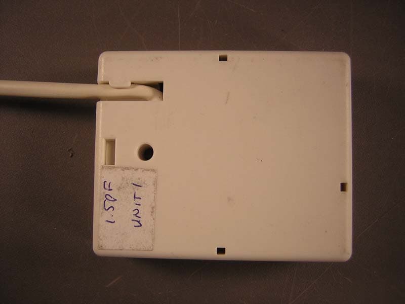
Click to zoom
Application Details
- Equipment Class
- DTS - Digital Transmission System
- Date of Grant
- May 16, 2006
- Application Purpose
- Original Equipment
- Date of Application
- May 16, 2006
- Equipment Note
- Wireless Adapter
- Frequency Range
- 2405.50000000 - 2480.40000000
- Country
- United States
Documents & Files
Document Text
Text extracted from the exhibit documents filed with the FCC. Open a document above to read the original.
Users Manual
Installation Instructions Wireless Adapter/Repeater © 2006 TAC / Tour Andover Controls, Inc., all rights reserved. Introduction TAC has designed a device that allows Andover Con- tinuum controllers to communicate with other controllers across a wireless field bus mesh network. The Andover Continuum Wireless Adapter/Repeater is a single device that can perform two roles — adapter and repeater. As a Wireless Adapter, the device is attached to the service port of a controller and allows the controller to communicate across a wireless mesh network with other controllers. The Wireless Adapter replaces the normal hard-wired network connection between control- lers. Power to the Adapter is supplied by the controller, through the service port. As a Wireless Repeater, the device is used to strength- en the mesh network by providing redundant routes to circumvent temporary or permanent obstructions. A robust mesh network is able to self heal by dynamically creating optimal routes. A Repeater may be needed when there are long distances between wireless-en- abled controllers, or to compensate for obstructions, such as pipes or walls that can attenuate or weaken the wireless signal between controllers. When the device is used as a wireless repeater, it is not connected to a controller, can be installed almost anywhere, and only requires a power source to function. i2/b3 Controller i2/b3 Controller i2/b3 Controller i2/b3 Controller i2/b3 Controller bCX Controller Wireless Repeater Wireless Repeater Wireless Adapter Wireless Adapter Wireless Adapter Wireless Adapter Wireless Adapter Ethernet Workstation Wireless Adapter .79 20 2.16 55 2.63 67 30-3001-887 Rev A Wireless Adapter/Repeater Installation Steps To install on a wall: 1) Locate an appropriate area to install the unit. 2) Locate the cover latch on the bottom of the unit and use a small screwdriver to squeeze the latch and and remove the cover from the unit. Note: The PC board is exposed. Handle with care to prevent damage to the components by electostatic discharge. 3) Place the unit in position. Mark the location of the mounting hole. 4) Use a drill to create a small pilot hole for a #6 (3.5mm) mounting screw, or for the wall anchor, if necessary. (Screw and wall anchor are provided.) 5) Insert the #6 mounting screw through the unit and into the wall, being careful not to over tighten and damage the electronics. 6) Snap the cover back in place. Note: The wireless adapter may be positioned so the cable comes out the top or bottom of the device. The cover can be installed in either direction. To hang vertically from a ceiling or object: 1) Make sure the unit is closed. 2) Insert a tywrap, wire, or thin cord through the mounting recess located in the top center of the unit. Cover Latch RS-485 Cable Outlet Mounting Recess Mounting Screw Cable Outlet Mounting Recess FrontInsideBack Long axis should be vertical for optimum performance Optional tywrap for hanging device vertically Installation Notes 1) Install the Adapter/Repeater with the long axis vertical for optimum performance. 2) Install away from metal or water-filled objects. These objects block or diminish the signal. 3) Install at a horizontal plane height where there are as few objects as possible. For example, in an office with cubicles, install the units two feet or so above the average cubicle wall height. This placement allows the adapters/repeaters to transmit across a horizontal plane that does not contain a lot of objects that can potentially block or diminish the signal. 4) Once installed, select a channel that is not normally used by other wireless applications. The default channel is 3, but you can reset the channel using the Andover Continuum Wireless Maintenance Tool. (Note: The frequencies of the TAC Wireless Adapter (802.15.4) channels do not line-up with Wi-Fi (802.11) channels. For example, TAC channel 3 is between Wi-Fi channels 1 and 2.) 3) Secure the unit, fastening the tywrap, wire, or thin cord over, through, or around the mounting object. ( i.e., eyehook, exposed screw, pipe, ceiling support, etc.) 4) Make sure the unit is secure. Connecting the Adapter to a Controller CPU INFINET (YELLOW) BACNET (GREEN) RESTART COMM PORT 1 RS-232 (DTE) N ( ) L ( ) INPUT POWER 24 VAC 40 VA 50/60 HZ 12-28 VDC 25W xP EXP PORT 24 VDC 400mA DCD RTS RD TD RD TD SHLD SERVICE C O M M P O R T 2 PORT RS-485 ETHERNET 10/100 BASE T RS 232 LINK/ACT 10/100 Mbps Controller RS- 485 Service Port Supplied 6 foot cable * Adapters with 25 foot cables are also available Wireless Adapter 1) Connect the Wireless Adapter to a controller’s service port using the RS-485 4-pin connector. 2) The controller will automatically recognize (“learn”) the other wireless devices on the wireless field bus (mesh network). Notes: On the bCX fieldbus, you must set the default mode of COMM2 to “Wireless.” A learn will discover wireless i2/b3 controllers that are properly configured Controllers with Hidden Service Port Connections On most Andover Continuum controllers, the service port connection is located outside the cover and labelled appropriately. How- ever, there are a few controllers where the service port connections are only accessable by removing the controller covers. The following illustration lists the controllers with internal service ports and identifies their approximate location on the controller circuit boards. Some of the controllers have service port connectors, so the correct pin orientation is guaranteed. For controllers that only have the four individual service port pins, the following illustration shows the correct orientaton of the Wireless Adapter cable’s connector, using the location of the connector’s raised tab. Service Port Connector i2/b3 865/866/885-V Controller Service Port Connector i2/b3 865/866 VAV Controller Service Port Pins i2/b3 885 VAV Controller Connector Tab i2/b3 887- L Controller Service Port Pins Service Port Pins i2/b3 887 Controller i2/b3 867 Controller Service Port Connector C…
Text truncated - open the document above for the full version.
Cover Letter(s)
TAC Phone +1 978-470-0555 One High Street Fax +1 978-470-0946 North Andover, MA 01845 USA Web www.tac.com May 12, 2006 Mike Buchholz Curtis – Strauss LLC 527 Great Road Littleton, MA 01460 UPDATED TECHNICAL DESCRIPTION: The Wireless Adapter operates in conjunction with other Wireless Adapters to form a wireless “mesh network” of our HVAC controller products. This wireless mesh network will replace our wired RS-485 hard wired network for customers who do not wish to install network wiring. The Wireless Adapter connects to the HVAC controller’s RS-485 port for obtaining power and communicating to the HVAC controller. The Wireless Adapter provides wireless communication between HVAC controllers allowing the formation of a wireless mesh network. The mesh network is so named since there is RF transmission overlap of several, but not all, nearby nodes (Wireless Adapters) in a mesh network. During system installation a“cost” table are determined and stored in each Wireless Adapter that lists the “cost” of transmission to nearby nodes. If node A needs to communicate data to node Z that is beyond its RF range the data packet must make several “hops”, via nearby nodes, in order to reach node Z. Cost is described in more detail in the “Repeater/Router Operation” section below and basically is a value of the likelihood a transmission from a routing node will reach a respective nearby node. The block diagram on Page 3 of the schematic diagram illustrates the Wireless Adapter design. Power and RS-485 communication are provided by the host controller over a 4 conductor cable. An LDO regulates the 3.3V input voltage down to the 3.0V system voltage. The 3.0V supply voltage powers the MCU, external SRAM, RF transceiver and RF power amplifier. An RS-485 transceiver converts the half duplex communication to/from RS-485 levels to CMOS/TTL signals for communication to/from the onboard Atmega128L MCU. An external SRAM is connected to the address and data bus of the MCU. Communication from the MCU to the 802.15.4 compliant EM2420 RF transceiver is achieved via an SPI bus. Also additional communication signals (interrupt signals, etc.) complete the communication between the MCU and RF transceiver. The output signal of the EM2420 RF transceiver is amplified by an external RF power amplifier. Two RF switches provide steering of the transmit and receive signals to/from the EM2420. An integral PCB mounted antenna completes the RF signal path. TCB Questions with answers : 1. Paper label is unacceptable. See Label exhibit. “60# matte white thermal transfer paper.” The FCC ID label material has been changed from a paper label to THERMLfilm SELECT 31800 from FLEXcon. It is a printable hard white polypropylene material, coated with a permanent pressure sensitive acrylic adhesive. See the Product Information sheet from FLEXcon for detailed information. 2. Duty cycle calculation is unacceptable. The description provided is anecdotal and does not contain a technical description of the transmitter on off cycles when imbedded in a worst case mesh. Please provide an analysis of the worst case 100 mS interval considering transmitter on-off times when working in a worst case repeat situation with a worst case routing repeat table. We note that the transmitter is only 0.4 dB below the anecdotal duty cycle. There is not much margin for error here. The theoretical worst case transmit duty cycle analysis is shown below. The analysis is for a worst case scenario based on the software stack from Ember Corporation utilized on the Wireless Adapter. The theoretical worst case duty cycle is independent of whether or not the node is in “repeater/router” operation or transmitting host controller packets and is independent of the size of the routing or “cost” table. This worst case transmit duty cycle calculation, shown below, can never be achieved strictly from host generated packets due to the latency of the RS-485 communication bus operating at 50kbaud between the wireless adapter and host controller. This theoretical worst case transmit duty cycle can only be achieved, if ever, during “repeater/router” operation. The result is that the theoretical maximum transmit duty cycle of the Wireless Adapter, which for all intents and purposes will never be achieved, is 27% in a 100msec interval. Worst case measured transmit duty cycle of a mesh network node in the TAC building in North Andover, MA is 12% to 13%. Listed below is a calculation from Ember Corporation of the theoretical worst case transmit duty cycle that their software stack is capable of generating. Please reference new measurement data based on the theoretical 27% worst case duty cycle. IEEE 802.15.4 2.4 GHz PHY Data Rate250000 bits / sec 31250 bytes / sec Symbols/byte2 sym / bytes Symbol Timing62500 sym / sec 0.000016 sec / sym Byte Timing0.000032 sec / byte PHY PSDU6 bytes 4 Preamble, SPD, Length Max Length127 bytes Total Packet Length133 bytes Maximum Time TX PKT0.004256 sec Long Frame Scenario: 1) TX Frame Assume Frame is Data Frame 2) Wait for ACK 3) Wait for LIFS 4) Repeat Long InterFrame Spacing (Slotted w/ ACK) Long Frame127 bytes Data Frame Payload102 bytes ACK Frame5 bytes tack12 sym LIFS40 sym ACK Frame11 bytes Backoff Period20 sym Maximum Backoff 7 Random between 0 and 7 Backoff Required2 Backoff Time60 sym Network Based Calculation Long InterFrame Spacing (Slotted w/ ACK) Long Frame127 bytes Data Frame Payload102 bytes ACK Frame5 bytes tack12 sym LIFS625 sym Single hop data indicates 10 ms inte ACK Frame11 bytes Backoff Period20 sym Maximum Backoff 7 Random between 0 and 7 Backoff Required2 Backoff Time60 sym Transmit Time TX Time (Packet) 0.004256 TX Time (ACK) 0.000352 Total TX Time (sec) 0.004608 Off Time Backoff Time 0.00192 tack(minimum) 0.000192 LIFS 0.01 Total Off Time 0.012112 Duty Cycle (On /total) 27% Calculated Network Performance 3. Please provide an acknowledgment from the applicant that they will “reduce the power level at channel 15 by -5” in all produc…
Text truncated - open the document above for the full version.
External Photos
REPORT: EG0097-1 FCC ID: DVE-WIRELESS EXHIBIT: External Photos MODEL: Wireless Adaptor _____________________________________________________________ _____________________________________________________________ Curtis-Straus LLC • 527 Great Road • Littleton, MA • TEL (978) 486-8880 • FAX (978) 486-8828 Page 1 of 1
ID Label/Location Info
PRODUCT INFORMATION THERMLfilm SELECT ® 31800 Product Description: THERMLfilm SELECT 31800 is a 2.6 mil gloss topcoated UL-recognized (indoor) thermal transfer printable hard white polypropylene, coated with a general-purpose, permanent pressure-sensitive acrylic adhesive, and backed with a roll-form release liner. • • • • PP 260 H White...........................................2.6 mil hard white polypropylene designed for economical, general purpose label applications. TC-387........................................................Topcoat resists smudging and abrasion when printed with resin and wax/resin thermal transfer ribbons. L-20.............................................................General-purpose, permanent pressure-sensitive acrylic adhesive provides a permanent bond to a wide range of surfaces. S50K-8........................................................50 lb. semi-bleached kraft release liner. Product Variations: None Economical, General Purpose Applications: Industrial: Materials tracking, inventory control, product identification, asset tracking, shipping, agency recognition Healthcare: Patient care tracking, radiology, medication dispensing Retail: Horticulture/nursery labels, jewelry labels • • • • • • • Features & Benefits: • Economical polypropylene label stock with proven performance Gloss white surface makes label graphics easy to read Compatible with color and black resin and wax/resin thermal transfer ribbons Printable with a wide range of conventional solvent and water-based inks Acrylic adhesive bonds well to a wide variety of application surfaces Liner is suitable for label sensing equipment with most thermal transfer printers UL-recognized (indoor) as part of a thermal transfer printing system which includes a ribbon and THERMLfilm SELECT 31800. FLEXcon’s thermal transfer printable films are recognized with UL Laboratories under 969 standard for Marking and Labeling Systems, file number MH16635 (N) and are listed in the recognized component directory under Section PGJI2, Component- Printing Materials Available in Quick-Ship for fast delivery Recommendations: Evaluate the intended ribbon and ink system for compatibility with this product under application conditions. This product is not intended for fan-foldable applications 1 FLEXcon Industrial Park, Spencer, MA 01562-2642 Telephone (508) 885-8200 FAX (508) 885-8400 www.FLEXcon.com THERMLfilm SELECT ® 31800 Page 2 PRODUCT DATA VALUE TEST METHOD Physical Properties: Thickness Film: 2.6 (66) +/- 10% ASTM D 3652 (Mils[microns]) Adhesive:0.8-0.9 (20-23) +/- 0.1 (3) Liner: 3.1 (79) +/- 10% Dimensional Stability (%) No shrinkage observed Applied Shrinkage: 24 hour dwell time on aluminum panel then 24 hours at 160°F (71°C) Chemical Resistance (non-printed stock) Household Cleaners: Mild Acid: Oil: Water: No effect on topcoat or adhesive No effect on topcoat or adhesive No effect on topcoat or adhesive No effect on topcoat or adhesive ASTM D 896 (Modified for 72 hour dwell time) Adhesion Properties: Ultimate Peel from various surfaces ASTM D 903 Average Oz/in (N/m) (Modified for 72 hour Stainless Steel 38 (418) dwell time) Acrylic 41 (451) Glass 43 (473) Expected Shear (hours) 15 ASTM D 3654 Method A a. 1 hr. dwell b. 1 sq. in. surface c. 4 lb. load Tack (gm/sq cm) 500 ASTM D 2979 Expected Exterior Life: Indoor use only Service Temperature Range: -40°F to 176°F (-40°C to 80°C) Minimum Application Temperature: 50°F (10°C) Storage Stability: Two years when stored at 70°F (21°C) and 50% relative humidity. Product Performance and Suitability All of the descriptive information, the typical performance data, and recommendations for the use of FLEXcon products shall be used only as a guide and do not reflect the specification or specification range for any particular property of the product. Furnishing such information is merely an attempt to assist you after you have indicated your contemplated use and shall in no event constitute a warranty of any kind by FLEXcon. All purchasers of FLEXcon products shall be responsible for independently determining the suitability of the material for the purpose for which it is purchased. No distributor, salesman, or representative of FLEXcon is authorized to give any warranty, guaranty, or make any representation in addition or contrary to the above. Form #100-365-6-012804/040293
ID Label/Location Info
REPORT: EG0097-1 FCC ID: DVE-WIRELESS EXHIBIT: Label Placement MODEL: Wireless Adaptor _____________________________________________________________ _____________________________________________________________ Curtis-Straus LLC • 527 Great Road • Littleton, MA • TEL (978) 486-8880 • FAX (978) 486-8828 Page 1 of 2 REPORT: EG0097-1 FCC ID: DVE-WIRELESS EXHIBIT: Label Placement MODEL: Wireless Adaptor _____________________________________________________________ _____________________________________________________________ Curtis-Straus LLC • 527 Great Road • Littleton, MA • TEL (978) 486-8880 • FAX (978) 486-8828 Page 2 of 2
ID Label/Location Info
.30 4X R.03 1.65 IC 1026A-WIRE FCC ID DVE-WIRELESS BACKGROUND SEE NOTE 1 BOTTOM OF LABEL FCC ID1A B A A B 1 2 3 4 4 3 2 1 REVISIONS DWG. REV. DESCRIPTION DATE APPD CHGD C HKD APPLICATION USED ON MDR 3/27/06 01-3002-605-r3 3 This drawing contains information which is that corporation's expressed written approval. MATERIAL DENSITY: PART WEIGHT: FINISH: MATERIAL: DRAWN CHKD APPD APPD DATE DATE DATE DATE REV DRAWING NO. SIZE TITLE: SCALE SHT. Tolerance Unless Otherwise Specified: Decimals: .XX +/-.01 .XXX +/-.005 proprietary and the property of Andover Angles: +/- 1/2 Degree B 01-3002-605-MU 1A LBL, FCC, WA, White 1 1 FULL M. ROGERS 12/1/05 SEE NOTE 3 Wireless Adapter 1FOR PROTOTYPE ONLY MDR 12/7/05 DATABASE REV. Controls Corporation and may not be used in whole or part for any purpose without OF NEXT ASSEMBLY REMOVED "#" ON LABEL MDR 2/15/06 01-3002-605-r22 CHGD NOTE #9 FROM 1/8" MDR 12/13/05 COMPLIANCE IS REQUIRED WITH EACH SHIPMENT. 01-3002-605-r1 NOTES: 1. BACKGROUND COLOR TO BE WHITE. 2. ALL LETTERING AND LINES TO BE COLOR BLACK. 3. MATERIAL: MATERIAL: 60 # MATTE WHITE THERMAL TRANSFER PAPER. PERMANENT, PRESSURE-SENSITIVE ADHESIVE BACKING WITH PEEL-OFF RELEASE LINER. CARRIER WIDTH NOT TO EXCEED 4.65". 4. GRAPHIC SIDE TO BE FREE OF ADHESIVE MATERIAL. 5. ROLL DIAMETER NOT TO EXCEED 6". 6. VENDOR TO BE "UL", "C-UL" LISTED. 7. DRAWING GRAPHICS ARE SHOWN TO ESTABLISH PROPER ORIENTATION AND/OR COLOR DEFINITION AND ONLY MIMIC THE REAL ARTWORK GRAPHICS. PLEASE REFER TO THE ARTWORK, 05-3002-605, FOR THE EXACT GRAPHIC DEFINITION. 8. ROLL/LABEL ORIENTATION: LABELS TO BE LOCATED FACING OUTWARD ON ROLL WITH LEADING EDGE BEING "BOTTOM OF LABEL". 9. MUST KEEP .20" SPACE ON ROLL BETWEEN LABELS. 10. A CERTIFICATE OF CONFORMANCE TO MATERIAL 01-3002-605-r1A
Internal Photos
REPORT: EG0097-1 FCC ID: DVE-WIRELESS EXHIBIT: Internal Photos MODEL: Wireless Adaptor _____________________________________________________________ _____________________________________________________________ Curtis-Straus LLC • 527 Great Road • Littleton, MA • TEL (978) 486-8880 • FAX (978) 486-8828 Page 1 of 1
RF Exposure Info
Prediction of MPE limit at a given distance Equation from page 18 of OET Bulletin 65, Edition 97-01 where:S = power density P = power input to the antenna G = power gain of the antenna in the direction of interest relative to an isotropic radiator R = distance to the center of radiation of the antenna Maximum peak output power EIRP13.80(dBm) 23.98832919(mW) Antenna gain(typical):0(dBi) Maximum antenna gain:1(numeric) Prediction distance:20(cm) Prediction frequency:2450(MHz) MPE limit for uncontrolled exposure at prediction frequency:1(mW/cm^2) Power densit y at prediction frequency:0.004772(mW/cm^2) Maximum allowable antenna gain:23.21269855(dBi) 2 4R PG S π =
Test Report
Curtis-Straus LLC is accredited by the American Association for Laboratory Accreditation for the specific scope of accreditation under Certificate Number 1627-01. This report may contain data which is not covered by the A2LA accreditation. _____________________________________________________________ Curtis-Straus LLC • 527 Great Road • Littleton, MA • TEL (978) 486-8880 • FAX (978) 486-8828 Test Report Report No EG0097-1 Client Tour Andover Controls 1 High Street North Andover, MA 01845 Phone 978-975-9570 FRN 0011099207 RSS-210 Issue 6; 47 CFR 15.247 Model Wireless Adaptor FCC ID DVE-WIRELESS IC 1026A-WIRE Equipment Type Digitally Modulated Equipment Code DTS Emission Designator 175KG1D Results As detailed within this report Prepared by _____________________ Evan Gould – Test Engineer Authorized by __________________________ Michael Buchholz – EMC Manager Issue Date 5/5/06 Conditions of issue This Test Report is issued subject to the conditions stated in ‘terms and conditions’ section of this report. REPORT: EG0097-1 FCC ID: DVE-WIRELESS IC: 1026A-WIRE _____________________________________________________________ _____________________________________________________________ Curtis-Straus LLC • 527 Great Road • Littleton, MA • TEL (978) 486-8880 • FAX (978) 486-8828 Page 2 of 22 Table Of Contents Summary......................................................................................................................... 3 Test Methodology............................................................................................................ 3 Statement of Conformity.................................................................................................. 3 EUT Configuration........................................................................................................... 3 Bandwidth....................................................................................................................... 3 Peak Power..................................................................................................................... 3 Spectral Density.............................................................................................................. 3 Band Edge Measurements.............................................................................................. 3 Radiated Spurious Emissions......................................................................................... 3 AC Line Conducted Emissions........................................................................................ 3 Voltage Variations........................................................................................................... 3 Test Equipment Used...................................................................................................... 3 Terms And Conditions..................................................................................................... 3 REPORT: EG0097-1 FCC ID: DVE-WIRELESS IC: 1026A-WIRE _____________________________________________________________ _____________________________________________________________ Curtis-Straus LLC • 527 Great Road • Littleton, MA • TEL (978) 486-8880 • FAX (978) 486-8828 Page 3 of 22 Summary This test report supports an application for certification of a transmitter operating pursuant to 47 CFR 15.247 and RSS-210(Annex 8). The product is the Tour Andover Controls Wireless Adaptor. It is a transmitter that operates in the range 2400- 2483.5MHz. Test Methodology Radiated emissions testing is performed according to the procedures specified in ANSI C63.4 (2003) and RSS-GEN. Emissions were maximized by rotating the device around three orthogonal axes as well as varying the test antenna’s height and polarity. The operating voltage was 4.5VDC. The environmental conditions are shown below. Date Temperature Humidity 1/30/06 23.6°C 22% 1/31/06 23.6°C 22% 2/1/06 24°C 21% 2/2/06 24.2°C 19% 5/3/06 20.7°C 33% Frequency range investigated: 0.15MHz – 25GHz Measurement distance: 0.15 – 30MHz Conducted 30MHz – 3GHz 3m 3 – 25GHz 1m Testing was performed radiated due to the integral antenna. The channels tested were 0 (2405.5MHz), 7 (2440.5MHz), and 15 (2480.4MHz). REPORT: EG0097-1 FCC ID: DVE-WIRELESS IC: 1026A-WIRE _____________________________________________________________ _____________________________________________________________ Curtis-Straus LLC • 527 Great Road • Littleton, MA • TEL (978) 486-8880 • FAX (978) 486-8828 Page 4 of 22 Statement of Conformity The Wireless Adaptor has been found to conform to the following parts of 47 CFR and RSS 210 as detailed below: RSS-GEN RSS 210 Part 15 Comments 5.3 15.15(b) There are no controls accessible to the user that vary the output power. 5.2 15.19 The label is shown in the label exhibit. 7.1.5 15.21 Information to the user is shown in the instruction manual exhibit. 15.27 No special accessories are required for compliance. 7.1.4 15.203 The antenna for this device is hardwired to the PCB. 2.6 15.205 15.209 The fundamental is not in a Restricted band and the spurious and harmonic emissions in the Restricted bands comply with the general emission limits of 15.209. 7.2.2 15.207 EUT meets the AC Line conducted emissions requirements of 15.207. A2.9 15.247 The unit complies with the requirements of 15.247 REPORT: EG0097-1 FCC ID: DVE-WIRELESS IC: 1026A-WIRE _____________________________________________________________ _____________________________________________________________ Curtis-Straus LLC • 527 Great Road • Littleton, MA • TEL (978) 486-8880 • FAX (978) 486-8828 Page 5 of 22 EUT Configuration EUT Configuration Work Order: G0097 Company: Tour Andover Controls Company Address: 1 High Street North Andover, MA 01845 Contact: Joe Burch Person Present: Joe Burch MNSN EUT: Wireless AdaptorUnit 1 EUT Description: Wireless Adaptor EUT Max Fre quency: 2480.5MHz Support Equipment: MNSN Dell Latitude LM laptopTS30GI7088446BYK4360A RadioShack AC Adaptor273-1662A- B&B Electro…
Text truncated - open the document above for the full version.
Test Setup Photos
REPORT: EG0097-1 FCC ID: DVE-WIRELESS EXHIBIT: Setup Photos MODEL: Wireless Adaptor _____________________________________________________________ _____________________________________________________________ Curtis-Straus LLC • 527 Great Road • Littleton, MA • TEL (978) 486-8880 • FAX (978) 486-8828 Page 1 of 2 Radiated Emissions REPORT: EG0097-1 FCC ID: DVE-WIRELESS EXHIBIT: Setup Photos MODEL: Wireless Adaptor _____________________________________________________________ _____________________________________________________________ Curtis-Straus LLC • 527 Great Road • Littleton, MA • TEL (978) 486-8880 • FAX (978) 486-8828 Page 2 of 2 Conducted Emissions
Contact Information
Applicant
Kevin McCandless(Regulatory Engineer)
Test Firm
BUREAU VERITAS CONSUMER PRODUCTS SERVICES, INC.Ozgur Ozturk
[email protected]978-486-8880
Technical Specifications
| # | Rule Parts | Frequency Range | Power Output |
|---|---|---|---|
| 1 | 15C | 2.41 GHz - 2.48 GHz | 24.00 mW |
Other Applications from Schneider Electric Buildings LLC
DVE-EBIOTPCWM
Dec 13, 2022Radio Module (not sold separately, part of the selected commercial products)
Equipment Class
DTS - Digital Transmission System
DVE-ROAMIO2
Mar 15, 2006HVAC CONTROL TRANSCEIVER
Equipment Class
DXX - Part 15 Low Power Communication Device Transmitter