DVE-ROAMIO2HVAC CONTROL TRANSCEIVER
Schneider Electric Buildings LLC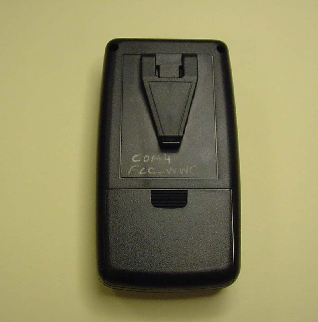
Click to zoom
Application Details
- Equipment Class
- DXX - Part 15 Low Power Communication Device Transmitter
- Date of Grant
- Mar 15, 2006
- Application Purpose
- Original Equipment
- Date of Application
- Mar 15, 2006
- Equipment Note
- HVAC CONTROL TRANSCEIVER
- Frequency Range
- 2402.00000000 - 2480.00000000
- Country
- United States
Documents & Files
Document Text
Text extracted from the exhibit documents filed with the FCC. Open a document above to read the original.
Block Diagram
2.4 Ghz Chip Antenna LMX9820A Bluetooth Module ROAMIO2 Functional Description SEPEC Power SUPPLY CPU Product Descreption The overall purpose of this project is to develop a BACnet/Infinet Service Tool that is designed to function with the BACnet/Infinet protocal. The intent of this application is to allow the Tour Andover Controls team and dealers to be more efficient in viewing the state of the I/O, modifying it or adding comments. This product is to communicat with a Laptop, PC or a handheld PDA device via the RS232/Bluetooth interface. The RS485 port is to be connected to the TAC service port avaialble on the, I1, I2 and the BACnet products. BACnet Infinet RS232 Transceiver 10MHZ Crystal Resonator RS485 Transceiver 8MHZ, 16pf Crystal 3.3 V o l t s VRS485(DC)= 3.3Volts(I2) 5.0Volts(I1) Vbat (DC)=3.0-1.6 Vin Range= 5.0-1.6Volts (DC)
External Photos
263-05 TAC ROAMIO TOP 263-05 TAC ROAMIO SIDE 263-05 TAC ROAMIO FRONT 263-05 TAC ROAMIO REAR
ID Label/Location Info
Label Positions
Internal Photos
263-05 TAC ROAMIO Battery compartment 263-05 TAC ROAMIO PCB Component Side 263-05 TAC ROAMIO Inside of Unit Cover Removed 263-05 TAC ROAMIO PCB Solder Side
Test Report
Compliance Worldwide, Inc. – 357 Main Street – Sandown, NH 03873 (603) 887 3903 Fax 887 6445 http://www.cw-inc.com TEST NUMBER - 263-05 TEST REPORT TO INDUSTRY CANADA RSS 210 SECTION 6.2.2 FEDERAL COMMUNICATIONS COMMISSION CFR47 PART15.249 Low Power License-Exempt Radio Communication Devices Intentional Radiators Radiated testing only for Tour Andover Controls 1 High Street N. Andover, MA 01845 (978) 975-9570 of ROAMIO with Bluetooth Model ROAMIOBT FCC ID: DVE-ROAMIO2 IC: 1026A-ROA on 8/12/2005 Tested By: Clifton P. Brick Reviewed By: Larry K. Stillings This report may not be duplicated, except in full without written permission from Compliance Worldwide, Inc. Page 2 of 24 Compliance Worldwide, Inc. – 357 Main Street – Sandown, NH 03873 (603) 887 3903 Fax 887 6445 http://www.cw-inc.com TEST NUMBER - 263-05 TABLE OF CONTENTS • Test Description • Test Results and Conclusions • Test Procedures • RSS 210 /Part 15 Subpart C Test Limits • Test Facility Description • Test Setup and Connection Information • Test Measurements and Results Radiated Measurements Radiated Output Power & Occupied Bandwidth Conducted Measurements • Notes and Comments Page 3 of 24 Compliance Worldwide, Inc. – 357 Main Street – Sandown, NH 03873 (603) 887 3903 Fax 887 6445 http://www.cw-inc.com TEST NUMBER - 263-05 TEST DESCRIPTION 1. TEST OBJECTIVE To test the ROAMIOBT OPL 9724 to RSS 210 / Part 15 Subpart C Rules and write a report. 2. E.U.T. DESCRIPTION GENERAL The ROAMIOBT is an industrial control component that operates in the 2400-2483.5 MHz Frequency Band. The ROAMIOBT uses FHSS modulation using channels on a 1MHz spacing on 79 channels from 2402 to 2480 MHz with approximately 1MHz occupied bandwidth per channel. SERIAL NUMBERS: production prototype Page 4 of 24 Compliance Worldwide, Inc. – 357 Main Street – Sandown, NH 03873 (603) 887 3903 Fax 887 6445 http://www.cw-inc.com TEST NUMBER - 263-05 TEST RESULTS AND CONCLUSIONS PRODUCT TESTED - ROAMIOBT MODEL NUMBER - ROAMIOBT RADIATED TEST RESULTS The test results show that the emissions radiated from this equipment are in compliance with IC Rules RSS 210 / FCC Rules Part 15 Subpart C. OCCUPIED BANDWIDTH & OUTPUT POWER The test results show that the occupied bandwidth and output power of this equipment are in compliance with IC Rules RSS 210 / FCC Rules Part 15 Subpart C . CONDUCTED TEST RESULTS The test results show that the emissions conducted through the power line from this equipment are in compliance with IC Rules RSS 210 / FCC Rules Part 15 Subpart C. ANALYSIS AND CONCLUSIONS Based upon the radiated measurements we find that this equipment is within the limits of the IC Rules RSS 210 / FCC Rules Part 15 Subpart C. All results are based on a test of one sample, and represent other production units, only in as much as a sample represents other production units. If any significant changes are made to the unit, the changes shall be evaluated and a retest may be required. NOTES (Special conditions unique to this test) None. Page 5 of 24 Compliance Worldwide, Inc. – 357 Main Street – Sandown, NH 03873 (603) 887 3903 Fax 887 6445 http://www.cw-inc.com TEST NUMBER - 263-05 TEST PROCEDURES 1. TEST EQUIPMENT A. HP 8593E (9 kHz - 26.5 GHz) Spectrum Analyzer, S/N 3829A03887. Calibration Date 1-17-2005, calibrated annually. B. Com-Power Biconilog Antenna, Model AC220, S/N 25509. Calibration Date 7-11-2005, calibrated annually. C. Electro-Metrics Double Ridged Guide Antenna, Model EM-6961, S/N 6337. Calibration Date: 7-30-2004, calibrated biannually. D. HP 1 - 26.5 GHz Preamplifier, Model 08449B, S/N 3008A01323. Calibration Date: 8-3-2004, calibrated biannually. 2. FREQUENCY RANGE TO BE SCANNED. A. Radiated Test from 30 MHz to 40 GHz (or the 10 th harmonic of the highest frequency whichever is lower). B. Conducted Test from 150 kHz to 30 MHz. Page 6 of 24 Compliance Worldwide, Inc. – 357 Main Street – Sandown, NH 03873 (603) 887 3903 Fax 887 6445 http://www.cw-inc.com TEST NUMBER - 263-05 3. TEST PROCEDURES. Radiated test procedure: The EUT, associated cables and peripheral devices are placed on the supporting table and any support equipment is placed off the site. The EUT is turned on and any necessary operating or test software installed and allowed to warm up. The EUT is pre-scanned in our ferrite tile lined chamber where it is rotated 360 degrees and examined in both horizontal and vertical polarization, the equipment was examined in three orthogonal planes, examined at 85 and 115 percent of input voltage or if battery operated new batteries were used. all emission frequencies are identified and recorded. The EUT is then moved to the OATS and the frequency band from 30 MHz to 40 GHz is scanned, all frequencies identified in the chamber are investigated, as well as harmonic frequencies of the EUT. When an emission is found the emission is maximized by varying the bundle position of the connecting cables, the antenna height, the antenna polarization (vertical and horizontal) and the table orientation (360 degrees). The maximum reading is recorded and the next signal is searched for. All measurements are made according to the procedures defined in: "ANSI C63.4-2003 American National Standard for Methods of Measurement of Radio-Noise Emissions from Low-Voltage Electrical and Electronic Equipment in the Range of 9 kHz to 40 GHz” (ISBN 0-7381-3844-4). Page 7 of 24 Compliance Worldwide, Inc. – 357 Main Street – Sandown, NH 03873 (603) 887 3903 Fax 887 6445 http://www.cw-inc.com TEST NUMBER - 263-05 RSS 210 TEST LIMITS 1. RSS 210 Section 6.2.2, Table 3 Radiation Limits (Quasi-Peak): FCC Part 15.209, 15.235, 15.249 Radiation Limits (Quasi-Peak): Frequency MHz Distance meters Limit dBμV/m Limit μV/m 1.705 - 30 30 29.5* 30* 30 - 88 3 40.0 100 49.82 - 49.90 3 80.0* 10,000* 88 - 216 3 43.5 150 216 - 960 3 46.0 200 902 - 928 3 94.0 50,000 2400 - 2483.5 3 94.0 50,000 960 - 1000 3 54.0 500 1000 - 40000 3 54.0* 500* *NOTE: Average Limits 2. RSS 210 Section 6.6a Conduction Limits (Quasi-P…
Text truncated - open the document above for the full version.
Test Setup Photos
263-05 TAC ROAMIO CONDUCTED FRONT 263-05 TAC ROAMIO CONDUCTED REAR 263-05 TAC ROAMIO RADIATED FRONT 263-05 TAC ROAMIO RADIATED REAR
Contact Information
Applicant
Kevin McCandless(Regulatory Engineer)
Test Firm
Compliance Worldwide, Inc.Larry Stillings
Technical Specifications
| # | Rule Parts | Frequency Range | Power Output |
|---|---|---|---|
| 1 | 15C | 2.40 GHz - 2.48 GHz | - |
Other Applications from Schneider Electric Buildings LLC
DVE-EBIOTPCWM
Dec 13, 2022Radio Module (not sold separately, part of the selected commercial products)
Equipment Class
DTS - Digital Transmission System
DVE-WIRELESS
May 16, 2006Wireless Adapter
Equipment Class
DTS - Digital Transmission System