DYFC7Web Cam
Primatronix Ltd
Click to zoom
Application Details
- Equipment Class
- JBP - Part 15 Class B Computing Device Peripheral
- Date of Grant
- Jun 22, 2006
- Application Purpose
- Original Equipment
- Date of Application
- Jun 22, 2006
- Equipment Note
- Web Cam
- Company
- Primatronix Ltd
- Country
- Hong Kong
Documents & Files
Document Text
Text extracted from the exhibit documents filed with the FCC. Open a document above to read the original.
Users Manual
Skype Video Pack - Quick Start Guide This guide provides a quick reference for installing your Skype Video Pack. •For technical support please email [email protected] or visit our website at www.voipvoice.com •For Frequently Asked Questions check the VoIPvoice forums at http://forums.voipvoice.com Connecting the Skype Video Pack Hardware 1. SkypeVideoCam -Connect the SkypeVideoCam to your computer’s USB port or a powered USB hub. 2. Ear-buds with integrated Microphone - As per the picture, plug the EarBud jack (with the headset picture) into the 3.5mm Line Out/Speakers socket on your computer. Plug the microphone jack (with the microphone picture) into the microphone socket on your PC. 3. Install Skype - Insert the mini CD into your CD Rom and follow the instructions on your screen. Kit vidéo Skype - Guide de mise en route rapide Référez-vous à ce guide pour procéder à l’installation rapide de votre kit vidéo Skype. •Si vous avez besoin d’assistance technique, veuillez nous contacter par courrier électronique à [email protected] ou visitez notre site Internet à www.voipvoice.com •Pour prendre connaissance des réponses aux questions les plus fréquemment posées, rendez-vous aux Forums VoIPvoice à http://forums.voipvoice.com Raccordement du matériel du kit vidéo Skype 1. VideoCam Skype : Raccordez la caméra VideoCam Skype au port USB de votre ordinateur ou à un hub USB alimenté. 2. Écouteurs avec microphone intégré : Comme indiqué sur l’illustration, enfichez le connecteur (jack) des écouteurs (avec l’image d’un casque) dans la prise de 3,5 mm de la ligne de sortie/haut-parleurs de votre ordinateur. Enfichez le connecteur (jack) du microphone (avec l’image d’un microphone) dans la prise microphone de votre ordinateur. 3. Installation de Skype : Insérez le mini-CD dans votre lecteur de CD-ROM et suivez les instructions données à l’écran. GB FR picture illustration figura Ohrhörerbild imagen 6LQ013YY Pacchetto Video Skype - Guida rapido di avvio La presente guida spiega come installare rapidamente il Pacchetto Video Skype. •Se vi occorre supporto tecnico, potete contattare tramite e-mail [email protected], oppure visitare il nostro sito Web a www.voipvoice.com •Potete trovare le Domande rivolte più spesso, e relative risposte, nei forum , VoIPvoice a http://forums.voipvoice.com Connessione del hardware del Pacchetto Video Skype 1. SkypeVideoCam - Collegare la SkypeVideoCam alla porta USB del computer, oppure ad un hub USB alimentato. 2. Complesso auricolari miniatura e microfono - Inserire, come da figura, la spina jack degli auricolari miniatura (con l’immagine delle cuffie) nella presa da 3,5 mm Linea uscita/Altoparlanti del computer. Inserire la spina jack del microfono (con l’immagine del microfono) nella presa per il microfono del PC. 3. Installazione di Skype - Inserire il CD miniatura nel lettore CD-ROM e seguire le istruzioni su schermo. Skype Video Pack - Schnellstartanleitung Diese Anleitung gibt Ihnen eine schnelle Übersicht beim Installieren Ihres Skype Video Packs. •Wen Sie technischen Support wünschen, schicken Sie bitte eine E-Mail an [email protected] oder besuchen Sie unsere Website unter www.voipvoice.com •Antworten zu häufig gestellten Fragen finden Sie in den VoIPvoice Foren unter http://forums.voipvoice.com Anschließen der Hardware des Skype Video Packs 1. SkypeVideoCam - Schließen Sie die SkypeVideoCam an den USB-Port Ihres Computers oder einen gespeisten USB-Hub an. 2. Ohrhörer mit integriertem Mikrofon - Den Stecker des Ohrhörers (mit dem Ohrhörerbild gekennzeichnet) wie auf der Abbildung gezeigt in die 3,5 mm Line-Out-(Audioausgang)/Lautsprecherbuchse am Computer stecken. Den Mikrofonstecker (mit dem Mikrofonbild gekennzeichnet) in die Mikrofonbuchse an Ihrem PC stecken. 3. Skype installieren - Die Mini-CD in das CD-Rom-Laufwerk einlegen und der auf dem Bildschirm angezeigten Anleitung folgen. Paquete Skype Video - Guía de Inicio Rápido Esta guía ofrece una referencia rápida para la instalación del Paquete Skype Video. •Para apoyo técnico por favor envíe un email a [email protected] o visite nuestras páginas web en www.voipvoice.com •Para las Preguntas Frecuentes mire los foros VoIPvoice en http://forums.voipvoice.com Conectando el Hardware del Paquete Skype Video 1. SkypeVideoCam -Conecte el SkypeVideoCam en el portal USB de su ordenador o en un aparato potenciado con tomas USB. 2. Auriculares con micrófono íntegro - Como se indica en la imagen, conecte el enchufe jack del Auricular (con la imagen de auricular) en el conector de salida de sonido/Altavoces de 3,5mm de su ordenador. Conecte el enchufe jack del micrófono (con la imagen de micrófono) en el conector de micrófono de su PC. 3. Instalar Skype - Inserte el mini CD en su CD Rom y siga las instrucciones en pantalla. IT DE ES Front side Back side Primatronix Ltd. Part No.: 6LQ013YY 6LQ013YY 6LQ013YY 6LQ013YY 6LQ013YY Rev.: 1 1 1 1 1 Model: C7 Skype C7 Skype C7 Skype C7 Skype C7 Skype Video PVideo P Video PVideo P Video P ackack ackack ack Description: Quick Star Quick Star Quick Star Quick Star Quick Star t Guidet Guide t Guidet Guide t Guide Scale: 1 : 1 1 : 1 1 : 1 1 : 1 1 : 1 Size: 130 x 130 130 x 130 130 x 130 130 x 130 130 x 130 mm Colour: Print: BlackBlack BlackBlack Black Background: WhiteWhite WhiteWhite White Material: 70 gsm wood fr 70 gsm wood fr 70 gsm wood fr 70 gsm wood fr 70 gsm wood fr ee paperee paper ee paperee paper ee paper Release Date: -- -- -- -- -- Charis Lo 25 May25 May 25 May25 May 25 May , 06, 06 , 06, 06 , 06
Block Diagram
Video/Image Controllers >> PC-CAM Controller >> SN9C120 SN9C120 single-chip PC camera controller [Enlarge Diagram] SN9C120 provides a low power-consumption, cost effective and superior image quality solution for PC camera controller with VGA image sensor. It integrates sensor interface, image signal processing, image compression and USB transfer function into one single chip. SN9C120 supports various image sensors with RGB Bayer pattern and comes with image signal processing blocks such as gamma and color correction, edge enhancement, auto exposure and auto white balance controls. The built-in JPEG compression engine makes the VGA frame rate up to 30fps on USB1.1 to come true. With the auxiliary hardware windowing and scaling, we can provide a variety of image format and also digital-zoom function to satisfy any special application demands. The driver of SN9C120 has passed Microsoft’s WHQL certification and it is 48-pin LQFP package without external memory needed. Drivers SN9C102P/105/110/12 0 (5213KB) SN9C102P/105/110/12 0 (1452KB) Data Sheet SN9C120_Spec_v1.0 Login Below To access documentati o and development tools product please Login or Email Address Forgot your Password? Login
External Photos
Test Setup FCC ID : DYFC7 External Photo - Front External Photo – Rear 0609721 0609721
Internal Photos
Test Setup FCC ID : DYFC7 Internal Photo - 1 Internal Photo - 2 Test Setup FCC ID : DYFC7 Internal Photo - 3
Operational Description
Technical Description Component Model Description Sensor SO1763A Image sensor DSP SN9C120 PC camera controller with sensor interface, image signal processing, image compression and USB transfer function 松翰科技股份有限公司 SONiX TECHNOLOGY CO., LTD. 本資料為松翰科技股份有限公司專有之財產,未經書面同意不准透露、使用,亦不准複印或轉變成任何其他形式使用。The information contained herein is the exclusive property of SONIX and shall not be distributed, reproduced or disclosed in whole or no in part without prior written permission of SONIX. - 1 - ver. 1.0 June, 2004 PC Camera Controller SN9C120 Preliminary Specification Released Version 1.0 May 24, 2004 Revision Number Date Description 0.1 May 18, 2004 A brief specification and release to Marketing 0.2 May 24, 2004 Detail descriptions 1.0 June 17, 2004 Released 松翰科技股份有限公司 SONiX TECHNOLOGY CO., LTD. 本資料為松翰科技股份有限公司專有之財產,未經書面同意不准透露、使用,亦不准複印或轉變成任何其他形式使用。The information contained herein is the exclusive property of SONIX and shall not be distributed, reproduced or disclosed in whole or no in part without prior written permission of SONIX. - 2 - ver. 1.0 June, 2004 Table of Content 1 GENERAL DESCRIPTION...........................................................................................................................................- 3 - 2 FEATURES.....................................................................................................................................................................- 3 - 3 SYSTEM APPLICATION..............................................................................................................................................- 4 - 4 FUNCTIONAL BLOCK DIAGRAM.............................................................................................................................- 4 - 5 PIN ASSIGNMENT........................................................................................................................................................- 5 - 6 ELECTRICAL CHARACTERISTICS..........................................................................................................................- 7 - 6.1 DC OPERATING CONDITION.....................................................................................................................................- 7 - 6.1.1 Absolute maximum ratings:................................................................................................................................- 7 - 6.1.2 Recommended operating conditions:..................................................................................................................- 7 - 6.1.3 DC electrical characteristics:............................................................................................................................- 7 - 6.2 AC OPERATING CONDITION.....................................................................................................................................- 7 - 7 SERIAL CONTROL INTERFACE...............................................................................................................................- 8 - 7.1 SERIAL BUS OVERVIEW............................................................................................................................................- 8 - 7.2 DATA TRANSFER FORMAT.........................................................................................................................................- 8 - 7.2.1 Master device transmits data to slave device (write cycle)..................................................................................- 8 - 7.2.2 Slave device transmits data to master device (read cycle)...................................................................................- 9 - 8 APPLICATION CIRCUIT...........................................................................................................................................- 10 - 9 PACKAGE INFORMATION.......................................................................................................................................- 11 - 松翰科技股份有限公司 SONiX TECHNOLOGY CO., LTD. 本資料為松翰科技股份有限公司專有之財產,未經書面同意不准透露、使用,亦不准複印或轉變成任何其他形式使用。The information contained herein is the exclusive property of SONIX and shall not be distributed, reproduced or disclosed in whole or no in part without prior written permission of SONIX. - 3 - ver. 1.0 June, 2004 1 General Description SN9C120 provides a low power-consumption, cost effective and superior image quality solution for PC camera controller with VGA image sensor. It integrates sensor interface, image signal processing, image compression and USB transfer function into one single chip. SN9C120 supports various image sensors with RGB Bayer pattern and comes with image signal processing blocks such as gamma and color correction, edge enhancement, auto exposure and auto white balance controls. The built-in JPEG compression engine makes the VGA frame rate up to 30fps on USB1.1 to come true. With the auxiliary hardware windowing and scaling, we can provide a variety of image format and also digital-zoom function to satisfy any special application demands. The driver of SN9C120 has passed Microsoft’s WHQL certification and it is 48-pin LQFP package without external memory needed. 2 Features ß Up to 30fps@VGA video streaming ß Support Image sensor with 9-bit RGB Bayer pattern raw data input ß Support CIF/VGA CMOS sensors, such as Hynix 7131D/E/R, Micron 0343/0360, OmniVision 7630/7648/7649, Pixart 106/202/302, IC-media, CI, NS, ...etc ß Provide pixel offset compensation and individual R/G/B digital color gain controls ß Provide defect pixel cancellation by EEPROM ß Provide hardware windowing, 1/2, 1/4 scaling function with smooth filter ß Provide programmable gamma and color correction ß Provide noise clearing and edge enhancement ß Embedded hardware color DSP and JPEG baseline capability of compression encoder ß Auto exposure control ß Auto white balance control ß Provide snapshot function ß Support operation mode in image quality/frame rate sele…
Text truncated - open the document above for the full version.
Test Report
• The test results reported in this test report shall refer only to the sample actually tested and shall not refer or be deemed to refer to bulk from which such a sample may be said to have been obtained. • This report shall not be reproduced except in full without prior authorization from Intertek Testing Services Hong Kong Limited. • For Terms And Conditions of the services, it can be provided upon request. • The evaluation data of the report will be kept for 3 years from the date of issuance. Intertek Testing Services Hong Kong Ltd. 2/F., Garment Centre, 576 Castle Peak Road, Kowloon, Hong Kong. Tel: (852) 2173 8888 Fax: (852) 2371 0521 Website: www.hk.intertek-etlsemko.com Primatronix Ltd. Application For Certification (FCC ID: DYFC7) Web Cam 0609721 BC/ Sandy Lee June 22, 2006 INTERTEK TESTING SERVICES FCC ID: DYFC7 i LIST OF EXHIBITS INTRODUCTION EXHIBIT 1: General Description EXHIBIT 2: System Test Configuration EXHIBIT 3: Emission Results EXHIBIT 4: Equipment Photographs EXHIBIT 5: Product Labelling EXHIBIT 6: Technical Specifications EXHIBIT 7: Instruction Manual INTERTEK TESTING SERVICES FCC ID: DYFC7 ii MEASUREMENT/TECHNICAL REPORT Primatronix Ltd. - MODEL: VOIP VOICE C7 CYBERSERIES C7 Skype C7 FCC ID: DYFC7 June 22, 2006 This report concerns (check one:) Original Grant X Class II Change Equipment Type: Computer Peripheral (example: computer, printer, modem, etc.) Deferred grant requested per 47 CFR 0.457(d)(1)(ii)? Yes No X If yes, defer until: date Company Name agrees to notify the Commission by: date of the intended date of announcement of the product so that the grant can be issued on that date. Transition Rules Request per 15.37? Yes No X If no, assumed Part 15, Subpart C for intentional radiator - the new 47 CFR [04-05-05 Edition] provision. Report prepared by: Chow Chi Ming, Billy Intertek Testing Services Hong Kong Ltd. 2/F., Garment Center, 576, Castle Peak Road, Kowloon, Hong Kong. Phone: 852-2173-8528 Fax: 852-2371-0521 INTERTEK TESTING SERVICES FCC ID: DYFC7 iii Table of Contents 1.0 General Description............................................................................................ 2 1.1 Product Description ............................................................................................ 2 1.2 Related Submittal(s) Grants ............................................................................... 2 1.3 Test Methodology............................................................................................... 3 1.4 Test Facility........................................................................................................ 3 2.0 System Test Configuration ................................................................................. 5 2.1 Justification ........................................................................................................ 5 2.2 EUT Exercising Software.................................................................................... 5 2.3 Special Accessories ........................................................................................... 5 2.4 Equipment Modification ...................................................................................... 5 2.5 Measurement Uncertainty .................................................................................. 5 2.6 Support Equipment List and Description ............................................................. 6 3.0 Emission Results ................................................................................................ 8 3.1 Field Strength Calculation................................................................................... 9 3.2 Radiated Emission Configuration Photograph................................................... 10 3.3 Radiated Emission Data ................................................................................... 11 3.4 Conducted Emission Configuration Photograph................................................ 13 3.5 Conducted Emission Data .....................................................................................14 4.0 Equipment Photographs ................................................................................... 18 5.0 Product Labelling.............................................................................................. 20 6.0 Technical Specifications ................................................................................... 22 7.0 Instruction Manual ............................................................................................ 24 INTERTEK TESTING SERVICES FCC ID: DYFC7 iv List of attached file Exhibit type File Description filename Test Report Test Report report.pdf Operation Description Technical Description descri.pdf Test Setup Photo Radiated Emission radiated photos.doc Test Setup Photo Conducted Emission conducted photos.doc Test Report Conducted Emission Test Result conducted.pdf External Photo External Photo external photos.doc Internal Photo Internal Photo internal photos.doc Block Diagram Block Diagram block.pdf Schematics Circuit Diagram circuit.pdf ID Label/Location Label Artwork and Location label.pdf User Manual User Manual manual.pdf INTERTEK TESTING SERVICES FCC ID: DYFC7 1 EXHIBIT 1 GENERAL DESCRIPTION INTERTEK TESTING SERVICES FCC ID: DYFC7 2 1.0 General Description 1.1 Product Description The Equipment Under Test (EUT) is a Web Cam. The EUT is connected to USB port when use. It can capture pictures or videos and stored them into digital format and saved in computer. The Model: CYBERSERIES C7 and Skype C7 are the same as the Model: VOIP VOICE C7 in hardware aspect. The difference in trade name serves as marketing strategy. For electronic filing, the brief circuit description is saved with filename: descri.pdf. 1.2 Related Submittal(s) Grants This is an application for certification of a computer peripheral. INTERTEK TESTING SERVICES FCC ID: DYFC7 3 1.3 Test Methodology Both AC mains line-conducted and radiated emis…
Text truncated - open the document above for the full version.
Test Setup Photos
Test Setup FCC ID : DYFC7 Conducted Photo - Front Conducted Photo - Rear Test Setup FCC ID : DYFC7 Conducted Photo - Side
Test Setup Photos
Report No.: 0609721 PC Live Mode AC Mains “L” Ctrl No.: N/A PAGE 1 Tested By:Hong, Report No.:0609721 Scan Settings (1 Range) |--------- Frequencies -----------||----------- Receiver Settings ------------| Start Stop Step IF BW Detector M-Time Atten Preamp OpRge 150k 30M 5k 10k PK+AV 10ms AUTO LN OFF 60dB Final Measurement: x QP / + AV Meas Time: 1 s Subranges: 16 Acc Margin: 20dB Transducer No. Start Stop Name 2 1 9k 30M EW0699 12 9k 30M EW0192 0 10 20 30 40 50 60 70 80 90 dBuV 100 0.15 MHz 30 110 F15Q F15A Report No.: 0609721 PC Live Mode AC Mains “L” Ctrl No.: N/A Tested By:Hong, Report No.:0609721 Scan Settings (1 Range) |--------- Frequencies -----------||----------- Receiver Settings ------------| Start Stop Step IF BW Detector M-Time Atten Preamp OpRge 150k 30M 5k 10k PK+AV 10ms AUTO LN OFF 60dB Final Measurement Results: Frequency QP Level QP Limit MHz dBuV dBuV 0.15000 44.5 66.0 15.37500 49.1 60.0 16.12500 48.6 60.0 Frequency AV Level AV Limit MHz dBuV dBuV 0.48500 28.9 46.3 0.58500 27.9 46.0 0.91500 29.0 46.0 1.52500 27.1 46.0 15.45000 40.4 50.0 15.51000 40.3 50.0 * limit Report No.: 0609721 PC Live Mode AC Mains “N” Ctrl No.: N/A PAGE 1 Tested By:Hong, Report No.:0609721 Scan Settings (1 Range) |--------- Frequencies -----------||----------- Receiver Settings ------------| Start Stop Step IF BW Detector M-Time Atten Preamp OpRge 150k 30M 5k 10k PK+AV 10ms AUTO LN OFF 60dB Final Measurement: x QP / + AV Meas Time: 1 s Subranges: 16 Acc Margin: 20dB Transducer No. Start Stop Name 2 1 9k 30M EW0699 12 9k 30M EW0192 0 10 20 30 40 50 60 70 80 90 dBuV 100 0.15 MHz 30 110 F15Q F15A Report No.: 0609721 PC Live Mode AC Mains “N” Ctrl No.: N/A Tested By:Hong, Report No.:0609721 Scan Settings (1 Range) |--------- Frequencies -----------||----------- Receiver Settings ------------| Start Stop Step IF BW Detector M-Time Atten Preamp OpRge 150k 30M 5k 10k PK+AV 10ms AUTO LN OFF 60dB Final Measurement Results: Frequency QP Level QP Limit MHz dBuV dBuV 0.15000 41.8 66.0 0.86500 33.5 56.0 8.14000 24.9 60.0 15.33500 46.7 60.0 15.74000 46.1 60.0 Frequency AV Level AV Limit MHz dBuV dBuV 0.48500 26.9 46.3 0.58000 27.9 46.0 0.91500 29.2 46.0 1.15500 25.8 46.0 1.52500 28.8 46.0 15.40500 36.5 50.0 15.60500 35.8 50.0 * limit
Contact Information
Applicant
Ricky Tse(Project Manager)
Technical Contact
Intertek Testing Services Hong KongAlfred Lo
[email protected]852-21738545
2/F Garment Center, · Kowloon · Hong Kong
Non-Technical Contact
Intertek Testing Services Hong KongAlfred Lo
[email protected]852-21738545
Test Firm
Intertek Testing Services Hong KongBilly Chow
Technical Specifications
| # | Rule Parts | Frequency Range | Power Output |
|---|---|---|---|
| 1 | 15B | - | - |
Other Applications from Primatronix Ltd
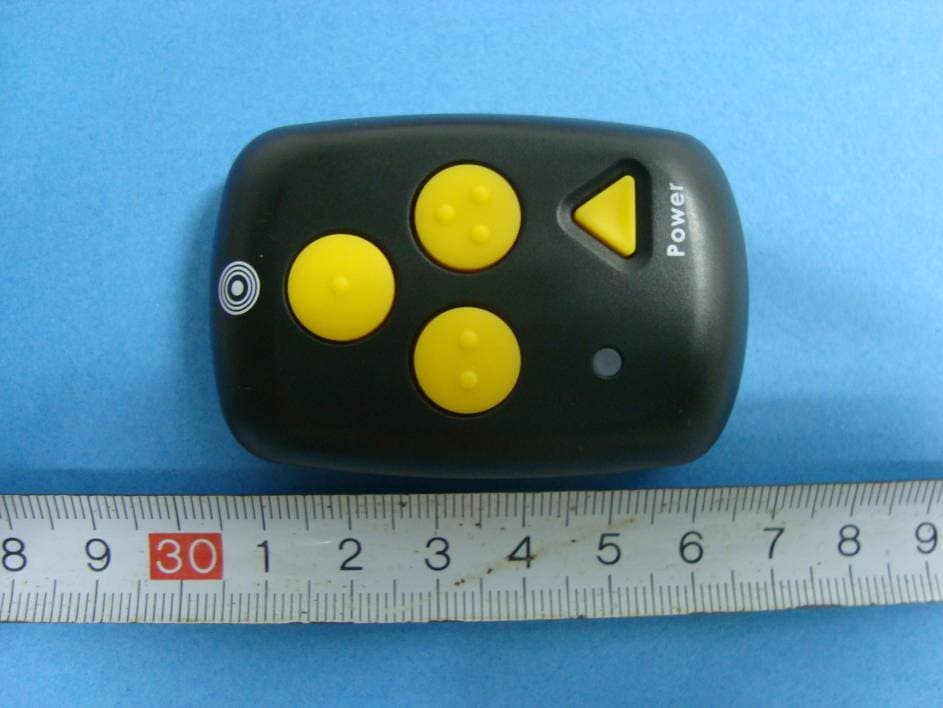
DYFSH200
Apr 21, 2010Remote Controller of Navigation and Information Reference Point System
Equipment Class
DSC - Part 15 Security/Remote Control Transmitter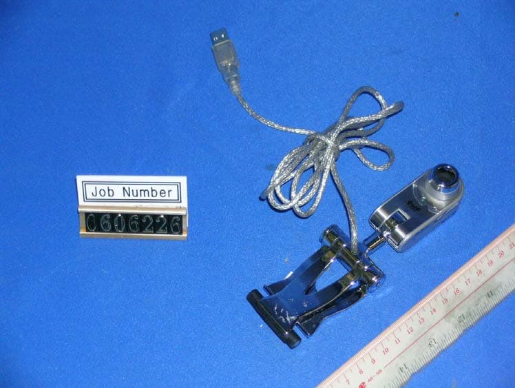
DYFC18
Sep 17, 2007Professional Webcam
Equipment Class
JBP - Part 15 Class B Computing Device Peripheral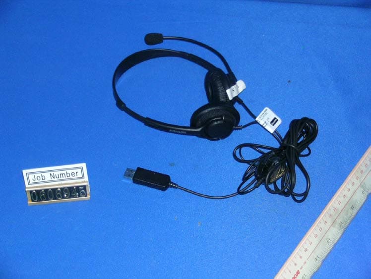
DYFV852
Sep 17, 2007USB Headset
Equipment Class
JBP - Part 15 Class B Computing Device Peripheral
DYFCV200RT
May 21, 2007433MHz Transceiver
Equipment Class
DSR - Part 15 Remote Control/Security Device Transceiver
DYF86708
Aug 15, 2006Bluetooth Headset
Equipment Class
DXT - Part 15 Low Power Transceiver, Rx Verified