DYFEMG900REmergency Pendant Telephone
Primatronix Ltd
Click to zoom
Application Details
- Equipment Class
- CYY - Communications Receiver used w/Pt 15 Transmitter
- Date of Grant
- Jul 26, 2006
- Application Purpose
- Original Equipment
- Date of Application
- Jul 26, 2006
- Equipment Note
- Emergency Pendant Telephone
- Frequency Range
- 868.35000000 - 868.35000000
- Company
- Primatronix Ltd
- Country
- Hong Kong
Documents & Files
Document Text
Text extracted from the exhibit documents filed with the FCC. Open a document above to read the original.
Users Manual
EMG900 EMERGENCY PENDANT TELEPHONE Instruction Manual All rights reserved by SOUTHERN TELELCOM INC. Models: EMG900 SOS Emergency Corded Telephone 1 TABLE OF CONTENTS FCC REGULATIONS............................... 2-3 Pause............................................. 27 IMPORTAIN SAFETY INSTRUCTIONS........ 4-5 Flash............................................. 27 BATTERY CAUTIONARY INSTRUCTIONS.. 6 Mute.............................................. 28 FEATURES............................................ 7-10 Hearing Aid Compatibility................... 28 INSTALLATION....................................... 11-13 Ringer Volume Control....................... 28 Installing batteries............................. 11 Receiver Volume Control.................... 28 Replace the battery of Pendant............ 12 THE PHONE BOOK................................. 29-35 Connecting the AC adaptor.................. 12 Store Numbers................................. 29-33 Connecting the telephone line.......... 12 Review Numbers.............................. 33 Hanging the Phone on the Wall............ 13 Dial Numbers................................... 34 SETTING UP.......................................... 14-25 Record Names................................. 34 Manu Key........................................ 14 Edit Names...................................... 34 Setting the LCD Contrast.................... 15 Delete Names................................. 35 Setting the ENTER TIME/DATE............ 15-17 EMERGENCY FEATURE.......................... 36-40 Setting the LCD LANGUAGE............... 18 Check the Message........................... 37 Setting the VOICE............................. 19-20 Delete the Message........................... 37 Setting the FLASH............................ 21 Store numbers M1/M2 Keys................ 38-39 Setting the TONE PULSE................... 22 Activate Emergency Call..................... 39-40 Setting the REMOTE PENDANT.......... 22-25 CALLER ID............................................ 41-42 TELEPHONE OPERATION....................... 26-29 Receiving a Call................................ 41 Dialing a Call.................................... 26 Erase Caller ID Memory..................... 42 Pre Dialing a Call.............................. 26 Call Back from Caller ID..................... 42 Receiving a Call............................... 26 Copy Caller ID to Phone Book.............. 42 Receiving a Call with Remote Pendant... 27 TROUBLESHOOTING............................. 43-44 Speaker Volume Control..................... 27 WATTANTY INFORMATION...................... 45 Redial............................................ 27 2 FCC REGULATIONS The FCC requires that you be advised of certain requirements involving the use of this telephone. 1. This equipment complies with Part 68 of the FCC rules. On the bottom of this equipment is a label that contains, among other information, the FCC registration number and Ringer Equivalence Number (REN) for this equipment. If requested, provide this information to your telephone company. 2. The REN is used to determine the quantity of devices you may connect to your telephone line and still have all of those devices right when your number is called. In most, but no all areas, the sum of all the REN’s of all devices should not exceed five (5.00). To be certain of the number of devices you may connect to your lines, as determined by the REN, you should call your local telephone company to determine the maximum REN for your calling area. 3. If your telephone causes harm to the telephone network, the telephone company may discontinue your service temporarily. If possible, they will notify you in advance. But if advance notice isn’t practical, you will be notified as soon as possible. You will be advise of your right to file a complaint with the FCC. 4. If your telephone company may make changes in it’s facilities, equipment, operations, or procedures that could affect the proper operation of your equipment. If they do, you will be given advance notice so that you can make the necessary modifications in order to maintain uninterrupted service. 5. If you experience trouble with the telephone, please contact the service center for repair/warranty information. Your telephone company may ask you to disconnect this telephone from the network until the problem has been corrected or you are sure that the equipment is not malfunctioning. 6. This equipment may not be used on coin service provided by the telephone. Connection to party lines is subject to state tariffs (contact your state public utility commission of corporation commission for information). This telephone complies with Part 15 of the FCC Rules and Regulations. Operation is subject to the following two conditions: (1) this telephone may not cause harmful interference, and (2) it must accept any interference received, including interference that may cause undesirable operation. 3 FCC REGULATIONS WARNING: CHANGES OR MODIFICATIONS TO THIS UNIT NOT EXPRESSLY APPROVED BY THE PARTY RESPONSIBLE FOR COMPLIANCE COULD VOID THE USER’S AUTHORITY TO OPERATE THE EQUIPMENT. NOTE: This equipment has been tested and found to comply with the limits for a class B digital device, pursuant to Part 15 of FCC Rules. These limits are designed to provide reasonable protection against harmful interference in a residential installation. This equipment generates, uses and can radiate radio frequency energy and, if not installed in accordance with the instructions, may cause harmful interference to radio communications. However, there is no guarantee that interference will not occur in a particular installation. If this equipment does cause harmful interference to radio or television reception, which can be determined by turning the equipment off and on, the user is encouraged to try to correct the problem by one or more of the following measures: z Reorient or relocate the receiving antenna z Reorient, relocate …
Text truncated - open the document above for the full version.
External Photos
INTERTEK TESTING SERVICES External Photos FCC ID: DYFEMG900R external photos - 1 of 2 INTERTEK TESTING SERVICES External Photos FCC ID: DYFEMG900R external photos - 2 of 2
ID Label/Location Info
DISCONNECT ALL TELEPHONE AND POWER LINES FROM THE WALL OUTLETS BEFORE REPLACING THE BATTERIES, SERVICING OR DISASSEMBLING THE EQUIPMENT. CAUTION: COMPLIES WITH 47 CFR PART 68. REQUIREMENTS REGISTRATION NO.: US: DYFTE12BEMG900 RINGER EQUIVALENCE: 1.2B REQUIRED CONNECTOR: U.S.O.C. JACK RJ11C MODEL NO.: EMG900 POWER SOURCE: 9VDC, 200mA FCC ID: DYFEMG900R Made Exclusively for Southern Telecom Inc. MADE IN CHINA HAC 1. This device may not cause harmful interference, and 2. This device must accept any interference received, including interference that may cause undesired operation. This device complies with Part 15 of the FCC Rules. Operation is subject to the following two conditions: 59284 L I D T S E ET R E T N K I US INFORMATION TECHNOLOGY EQUIPMENT This device complies with Part 15 of the FCC Rules. Operation is subject to the following two conditions: 1. This device may not cause harmful interference, and 2. This device must accept any interference received, including interference that may cause undesired operation. FCC ID: DYFEMG900T LABEL (Print White on Black label) Silk: Black Silk: Black M O D E L : T I T L E : B R A N D : C O U N T R Y : U P P E R C O L O U R : W I T H S P R A Y O R W I T H O U T S P R A Y S I L K : D O C N O . : D W N : A P P : D A T E : R E V . : P A G E O F I S S U E D D A T E : U P P E R P R I M A T R O N I X E M G 9 0 0 ( C D 8 1 0 ) O U T L I N E D R A W I N G L I F E L I N E U . S . A S I L V E R ( # 8 4 0 0 C ) B L A C K U S A \ G T P \ E M G 9 0 0 \ L 1 L I N D A C H E U N G D 3 4 1 0 , M A R 0 6 USE 12 VOLT ALKALINE BATTERY ONLYUSE 12 VOLT ALKALINE BATTERY ONLY MADE IN CHINA 5 7 . 2 m m 58mm 36mm 61mm
Internal Photos
INTERTEK TESTING SERVICES Internal photos FCC ID: DYFEMG900R internal photos - 1 of 11 Internal Photo - 1 Internal Photo - 2 INTERTEK TESTING SERVICES Internal photos FCC ID: DYFEMG900R internal photos - 2 of 11 Internal Photo - 3 Internal Photo - 4 INTERTEK TESTING SERVICES Internal photos FCC ID: DYFEMG900R internal photos - 3 of 11 Internal Photo - 5 Internal Photo - 6 INTERTEK TESTING SERVICES Internal photos FCC ID: DYFEMG900R internal photos - 4 of 11 Internal Photos - 7 Internal Photos - 8 INTERTEK TESTING SERVICES Internal photos FCC ID: DYFEMG900R internal photos - 5 of 11 Internal Photos - 9 Internal Photos - 10 INTERTEK TESTING SERVICES Internal photos FCC ID: DYFEMG900R internal photos - 6 of 11 Internal Photos - 11 Internal Photos - 12 INTERTEK TESTING SERVICES Internal photos FCC ID: DYFEMG900R internal photos - 7 of 11 Internal Photos - 13 Internal Photos - 14 INTERTEK TESTING SERVICES Internal photos FCC ID: DYFEMG900R internal photos - 8 of 11 Internal Photos - 15 Internal Photos - 16 INTERTEK TESTING SERVICES Internal photos FCC ID: DYFEMG900R internal photos - 9 of 11 Internal Photos - 17 Internal Photos - 18 INTERTEK TESTING SERVICES Internal photos FCC ID: DYFEMG900R internal photos - 10 of 11 Internal Photos - 19 Internal Photos - 20 INTERTEK TESTING SERVICES Internal photos FCC ID: DYFEMG900R internal photos - 11 of 11 RX PCB front side RX PCB rear side
Operational Description
1 of 2 Technical Description Company name: PRIMATRONIX LTD Model no.: CD810 (Receiver and corded phone) Date: May 29, 2006 1. General description This device is a friendly big button corded phone with a LCD display, caller ID function with speakerphone and wireless emergency pendant. 2. Circuit description This device contains only a receiver part and a corded phone circuit. The receiver MUST BE PAIRED UP with the corresponding transmitter before use. A. Receiver Portion The encoded ASK signal will be received by the antenna 1. Then the received signal will be amplified by the amplifier circuit and pass through a SAW resonator (SAW1) at 868.35 MHz to eliminate unwanted out-band signal. Then the signal will be demodulated by ASK receiver (TDA5200). Actually, this ASK receiver (TDA5200) is a single conversion receiver with an on-chip fully integrated PLL frequency synthesizer and an IF of nominal 10.7MHz. The demodulated signal (encoded data) will be sent to the MCU (EM78811). Then the MCU will compare this encoded data with the security code that pair up with the transmitter before. If the received encoded data is the same as the security code, then transmission is allowed between the transmitter and this receiver. And this MCU (EM78811) can undergo a pair up process with up to 5 individual transmitters. B. Corded phone Portion The following are the detailed function explanation of IC components: - EM78811 is an 8-bit CID (Call Identification) RISC type microprocessor. It provide LCD driver, FSK decoder, DTMF generator and CID of calling message display. - MC34018 is a speaker-phone integrated circuit incorporates the necessary functions to produce a high quality hands-free speaker-phone function; - HT9170D is a Dual Tone Multi Frequency (DTMF) receiver; - ISD5108 is a voice recorder IC with recorder time from 4-8 minutes; - HC374 is octal D-type flip-flops that functions a buffer; 2 of 2 - TA31002 is used provide multiple selection for the ringer tone; - 6202P502 is a regulator, which is used to provide a stable DC power. 3. Security coding information This device contains an encoder IC. The length of security code is 20 bit, which can provide up to 2 20 ~ 1 million different codes. When the pairing button is pressed on the phone base and SW1 is pressed at the transmitter side, the encoder at the transmitter side will generate a random security code. The decoder at the receiver side will then recognize and ‘remember’ this security code from the transmitter. Then this recognized security code will be used for each transmission for each pair up transmitter and receiver. This security code will only be changed when the pairing procedure is being taken again. As the length of the security code is significantly long, therefore it can minimize the possibility of code ‘collision’.
Test Report
Intertek Testing Services Hong Kong Ltd. 2/F., Garment Centre, 576 Castle Peak Road, Kowloon, Hong Kong. Tel: (852) 2173 8888 Fax: (852) 2371 0521 Website: www.hk.intertek-etlsemko.com May 30, 2006 Primatronix Ltd. 21/F., QPL Industrial Building, 126-140 Texaco Road, Tsuen Wan, N.T., Hong Kong. Dear Mr. Ricky Tse: Enclosed you will find your file copy of a Part 15 Certification (FCC ID: DYFEMG900R). For your reference, TCB will normally take another 15-20 days for reviewing the report. Approval will then be granted when no query is sorted. Please contact me if you have any questions regarding the enclosed material. Sincerely, Lam Chun Cheong, Kenneth Senior Lead Engineer Enclosure • The test results reported in this test report shall refer only to the sample actually tested and shall not refer or be deemed to refer to bulk from which such a sample may be said to have been obtained. • This report shall not be reproduced except in full without prior authorization from Intertek Testing Services Hong Kong Limited. • For Terms And Conditions of the services, it can be provided upon request. • The evaluation data of the report will be kept for 3 years from the date of issuance. Intertek Testing Services Hong Kong Ltd. 2/F., Garment Centre, 576 Castle Peak Road, Kowloon, Hong Kong. Tel: (852) 2173 8888 Fax: (852) 2371 0521 Website: www.hk.intertek-etlsemko.com Primatronix Ltd. Application For Certification (FCC ID: DYFEMG900R) Superheterodyne Receiver 0601614 KL/ Ann Choy May 30, 2006 INTERTEK TESTING SERVICES FCC ID: DYFEMG900R i LIST OF EXHIBITS INTRODUCTION EXHIBIT 1: General Description EXHIBIT 2: System Test Configuration EXHIBIT 3: Emission Results EXHIBIT 4: Equipment Photographs EXHIBIT 5: Product Labelling EXHIBIT 6: Technical Specifications EXHIBIT 7: Instruction Manual EXHIBIT 8: Miscellaneous Information INTERTEK TESTING SERVICES FCC ID: DYFEMG900R ii MEASUREMENT/TECHNICAL REPORT Primatronix Ltd. - MODEL: CD810 EMG900 FCC ID: DYFEMG900R This report concerns (check one:) Original Grant X Class II Change _____ Equipment Type: CYY - Low Pwr Com. Rx used w/ Pt 15 Tx Deferred grant requested per 47 CFR 0.457(d)(1)(ii)? Yes No X If yes, defer until: date Company Name agrees to notify the Commission by: date of the intended date of announcement of the product so that the grant can be issued on that date. Transition Rules Request per 15.37? Yes No X If no, assumed Part 15, Subpart B for unintentional radiator - the new 47 CFR [04-05-05 Edition] provision. Report prepared by: Lam Chun Cheong, Kenneth Intertek Testing Services Hong Kong Ltd. Hong Kong Ltd. 2/F., Garment Centre, 576, Castle Peak Road, Kowloon, Hong Kong. Phone: 852-2173-8474 Fax: 852-2741-1693 INTERTEK TESTING SERVICES FCC ID: DYFEMG900R iii Table of Contents 1.0 General Description .........................................................................................2 1.1 Product Description ............................................................................................2 1.2 Related Submittal(s) Grants ...............................................................................2 1.3 Test Methodology...............................................................................................3 1.4 Test Facility ........................................................................................................3 2.0 System Test Configuration ..............................................................................5 2.1 Justification ........................................................................................................5 2.2 EUT Exercising Software ...................................................................................5 2.3 Special Accessories ...........................................................................................5 2.4 Equipment Modification ......................................................................................6 2.5 Measurement Uncertainty ..................................................................................6 2.6 Support Equipment List and Description ............................................................6 3.0 Emission Results .............................................................................................8 3.1 Field Strength Calculation ..................................................................................9 3.2 Radiated Emission Configuration Photograph ..................................................10 3.3 Radiated Emission Data...................................................................................11 3.4 Conducted Emission Configuration Photograph ...............................................13 3.5 Conducted Emission Data................................................................................14 4.0 Equipment Photographs ................................................................................16 5.0 Product Labelling ...........................................................................................18 6.0 Technical Specifications ...............................................................................20 7.0 Instruction Manual .........................................................................................22 8.0 Miscellaneous Information ............................................................................24 8.1 Discussion of Pulse Desensitization .................................................................25 8.2 Calculation of Average Factor ..........................................................................26 8.3 Emissions Test Procedures..............................................................................27 INTERTEK TESTING SERVICES FCC ID: DYFEMG900R iv List of attached file Exhibit type File Description filename Test Report Test Report report.pdf Operation Description Technical Description descri.pdf Test Setup Photo Radiated Emission config photos.doc Test Setup Photo Conducted Emission config photos.doc T…
Text truncated - open the document above for the full version.
Test Report
Report No.: 0601614 Rx Mode Ctrl No.: N/A PAGE 1 Tested By:Hong, Report No.:0601614 Scan Settings (1 Range) |--------- Frequencies -----------||----------- Receiver Settings ------------| Start Stop Step IF BW Detector M-Time Atten Preamp OpRge 150k 30M 5k 10k PK+AV 10ms AUTO LN OFF 60dB Final Measurement: x QP / + AV Meas Time: 1 s Subranges: 16 Acc Margin: 20dB Transducer No. Start Stop Name 2 1 9k 30M EW0699 12 9k 30M EW0192 0 10 20 30 40 50 60 70 80 90 dBuV 100 0.15 MHz 30 110 F15Q F15A Report No.: 0601614 Rx Mode Ctrl No.: N/A Tested By:Hong, Report No.:0601614 Scan Settings (1 Range) |--------- Frequencies -----------||----------- Receiver Settings ------------| Start Stop Step IF BW Detector M-Time Atten Preamp OpRge 150k 30M 5k 10k PK+AV 10ms AUTO LN OFF 60dB Final Measurement Results: no Results
Test Setup Photos
INTERTEK TESTING SERVICES The Worst Case Configuration Photographs FCC ID: DYFEMG900R config photos (radiated emission – base unit) - 1 of 1 Radiated Emission Front View Rear View INTERTEK TESTING SERVICES The Worst Case Configuration Photographs FCC ID: DYFEMG900R config photos (conducted emission) - 1 of 2 Conducted Emission Front View Right Side View INTERTEK TESTING SERVICES The Worst Case Configuration Photographs FCC ID: DYFEMG900R config photos (conducted emission) - 2 of 2 Conducted Emission Left Side View
Contact Information
Applicant
Ricky Tse(Project Manager)
Technical Contact
Intertek Testing Services Hong Kong Ltd.Tommy Leung
[email protected]852-2173-8538
2/F., Garment Centre, · Kowloon · Hong Kong
Non-Technical Contact
Intertek Testing Services Hong Kong Ltd.Tommy Leung
[email protected]852-2173-8538
Test Firm
Intertek Testing Services Hong KongBilly Chow
Technical Specifications
| # | Rule Parts | Frequency Range | Power Output |
|---|---|---|---|
| 1 | 15B | 868.35 MHz - 868.35 MHz | - |
Other Applications from Primatronix Ltd
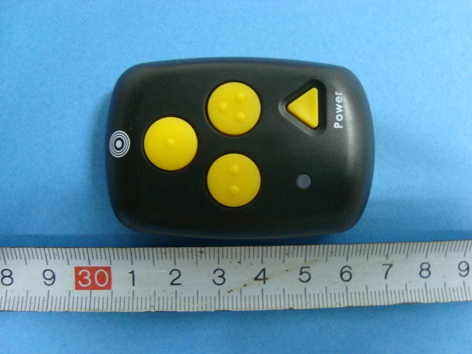
DYFSH200
Apr 21, 2010Remote Controller of Navigation and Information Reference Point System
Equipment Class
DSC - Part 15 Security/Remote Control Transmitter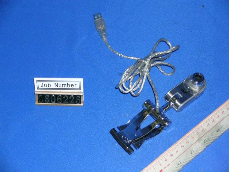
DYFC18
Sep 17, 2007Professional Webcam
Equipment Class
JBP - Part 15 Class B Computing Device Peripheral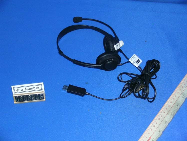
DYFV852
Sep 17, 2007USB Headset
Equipment Class
JBP - Part 15 Class B Computing Device Peripheral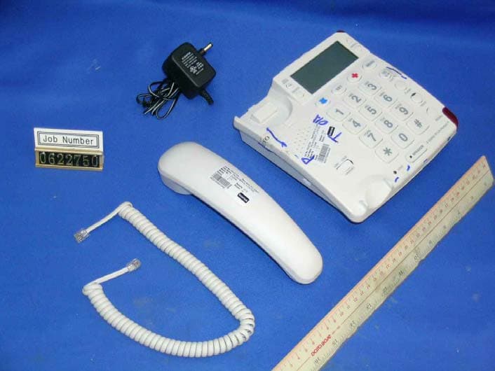
DYFCV200RT
May 21, 2007433MHz Transceiver
Equipment Class
DSR - Part 15 Remote Control/Security Device Transceiver
DYF86708
Aug 15, 2006Bluetooth Headset
Equipment Class
DXT - Part 15 Low Power Transceiver, Rx Verified