DYY24102410 ManPack HF Transceiver
Codan Limited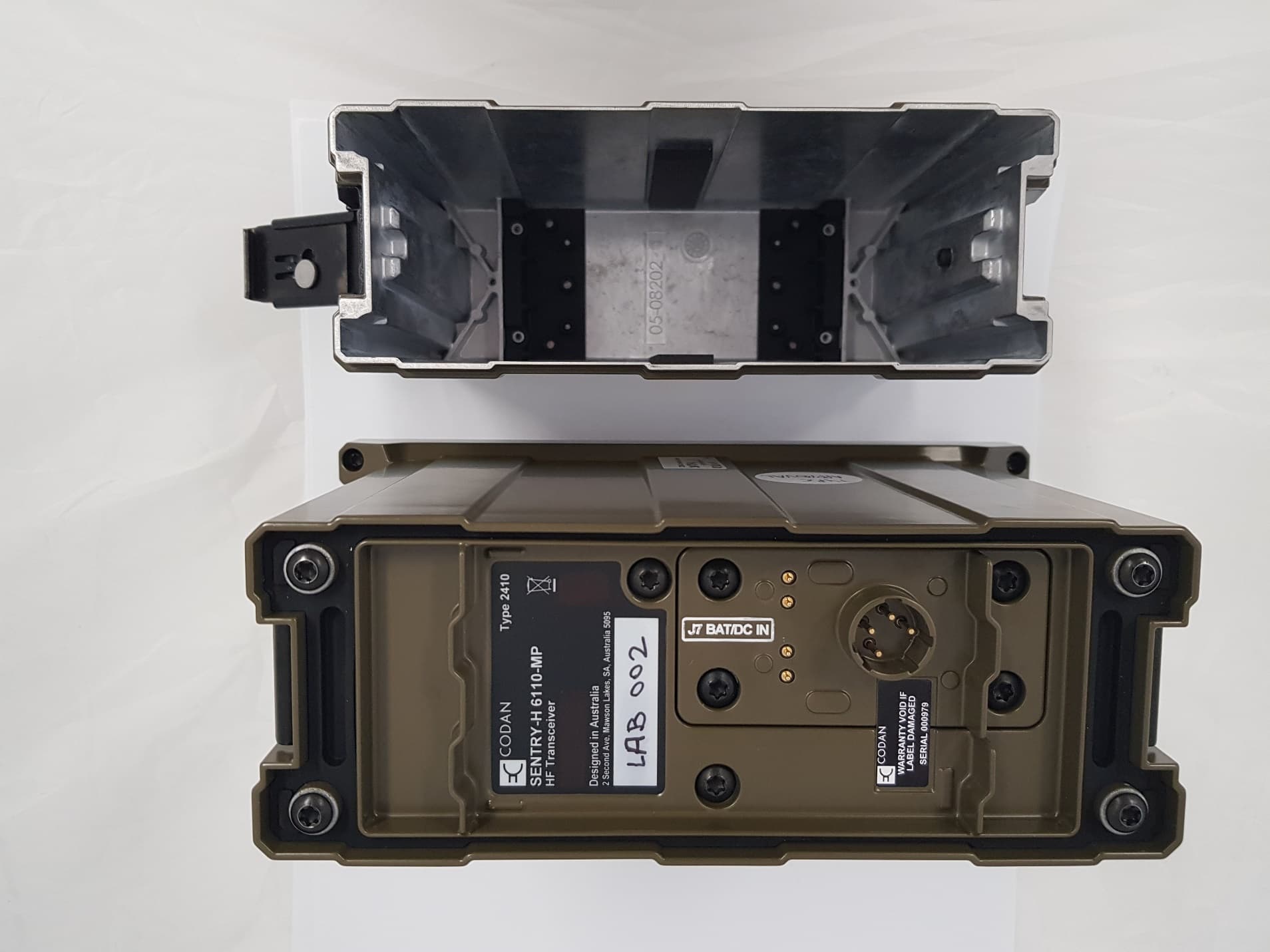
Click to zoom
Application Details
- Equipment Class
- TNB - Licensed Non-Broadcast Station Transmitter
- Date of Grant
- Feb 24, 2020
- Application Purpose
- Original Equipment
- Date of Application
- Feb 24, 2020
- Equipment Note
- 2410 ManPack HF Transceiver
- Frequency Range
- 1.60000000 - 30.00000000
- Company
- Codan Limited
- Country
- Australia
Documents & Files
Document Text
Text extracted from the exhibit documents filed with the FCC. Open a document above to read the original.
Users Manual
Quick Reference Card Fixed channel operation To operate on a fixed channel: ☐Go to the channel screen, stop scanning, then select a channel. ☐Press PTT to tune the antenna, if required. Discreet mode switch Rx/Tx level indicator Rx/Tx indicator channel name status areas left software key right software key volume/speaker mode indicator menu bar mode indicator Tx/Rx frequency battery level indicator missed call icon mute type indicator (highlighted when mute is on) call type indicator Tx power setting Pull, then rotate right to zeroise transceiver Discreet mode on (No audio or backlight) Discreet mode o Keys Volume down/up (when is present) Select channel Scroll left/up/down/right Menu/action Selection PressStart call Hold (for 2 sec)Go to Stations list End call, start/stop scan Mute on/off Manual tune screen Next speaker mode Next Digital Voice Rate Free tune receive Set transmit power level Select mute type Toggle between Analogue and Secure/DV Go to GPS screen Toggle Channel/Station screens Go to Adjust Display Brightness screen FUNC 2 Function Select: Self Tests Screen/Macros Screen Stations Call history Single call available for station Multiple calls available for station Basics Calling Call Types SelectiveGet Status MessageChannel Test Send PositionPhone Get PositionAlert ALE SoundingSMS Voice MessageTOD Request TOD Broadcast Making a Station Call To make a call using one of your pre-defined stations: ☐Go to the channel screen, then hold CALL or press Key 0. Stations Call history Single call available for station Multiple calls available for station ☐Scroll to the station that you want to call. ☐If there are multiple calls available for the station, press or CALL, then scroll to the desired call type. ☐Press CALL. ☐Respond to any prompts, then press CALL. © Codan Limited 201906-03050-EN Issue 1 Making a call from the Channel screen To make a call: ☐Go to the channel screen, then press CALL. AddressHF networkCall type Incoming call Missed call Outgoing call Options > Select HF network ☐Press or to scroll to the call type that you want to use. ☐Enter a Station ID to call. ☐If you want to return or repeat a call from the Call Log, press to scroll to the entry. ☐Press CALL. Navigating Making a call from the Call History To make a call from the call History: ☐Go to the channel screen, hold CALL or press key 0. ☐Ensure that the top tab is selected, then press to see the Call History. ☐Scroll to the call that you want to return or repeat, then press CALL. Making an alert call CAUTION: Ensure that all information required is set up for the alert station. To make an alert call: ☐Hold for 2 sec, then follow any prompts. Viewing missed calls To view a missed call: ☐Go to the channel screen, hold CALL, or press key 0, then press to see the Call History. ☐Scroll to the missed call that you want to view, then press OK. Navigating the menu structure To navigate the menu structure: ☐To move through the menu structure, press , , or to highlight the icon that you want to select, then press OK. ☐To move through a list of entries at the lowest level of the menu structure, press or . ☐To go to the top level in the menu structure, do one of the following: • Press (Close) to return to the top level of the menu structure, one level at a time. • Press PTT to exit to the channel screen, then press (Menu) to enter the top level of the menu structure. Finding a word or value NOTE:Find is available for selected icons. To find a word or value: ☐Highlight the icon in which you want to search, then press (Find). ☐Start entering the letter and/or number on which you want to search. ☐Enter more characters to refine your search. ☐Scroll to the entry or value that you want, then press OK. You are taken to the entry or name level of the user data containing the character. Text editing functions Press to delete a single character of hold to clear all the text in the field FUNC 2 Change character-entry mode Select special character (press/hold) Enter a space PTT Abort editing/exit Shortcuts + 0Adjust Display Brightness + 1Toggle next available theme + 2Toggle advanced view + 3Select language + Abandon mode References Sentry ® -H 6110-MP Transceiver Operator Guide (Codan part number 15-04200-EN)
Users Manual
Sentry-H 6110-MP OPERATOR GUIDE No part of this manual may be reproduced, transcribed, translated into any language or transmitted in any form whatsoever without the prior written consent of Codan Communications. © Copyright 2019 Codan Communications. Codan part number 15-04200-EN Issue 1, December, 2019. CODAN®, Sentry®, and CALM® are trademarks of Codan Limited. Other brand, product, and company names mentioned in this document are trademarks or registered trademarks of their respective holders. The English version takes precedence over any translated versions. Table of Contents Preparing your radio Charging and installing batteries................................................................................................3 Attaching a ground wire to the radio..........................................................................................5 Inserting a 6110-MP into a backpack........................................................................................7 Selecting and connecting your antenna.....................................................................................8 Testing your radio before deployment.....................................................................................10 Operating the radio Front panel and screen overview.............................................................................................15 Handsets..................................................................................................................................23 Speaker and mute....................................................................................................................25 Discreet mode and zeroise.......................................................................................................27 Secure communications...........................................................................................................29 Entering and editing text..........................................................................................................32 Operational screen modes Scanning, channel and scratch modes....................................................................................34 Calling HF Networks.............................................................................................................................37 Call types..................................................................................................................................39 Answering and ending a call....................................................................................................42 Making a 2G or 3G ALE call.....................................................................................................43 Making a Selcall call.................................................................................................................49 Stations Adding a Station.......................................................................................................................50 GPS Viewing GPS Information.........................................................................................................52 Appendix Update the radio profile with a USB thumb drive....................................................................54 TABLE OF CONTENTS i Troubleshooting.......................................................................................................................56 Definitions.................................................................................................................................62 Menu Navigation......................................................................................................................65 TABLE OF CONTENTS ii Charging and installing batteries Check batteries Before any deployment, it is vital to ensure that your batteries are fully charged and that you have a sufficient number of batteries for your mission. Compatible batteries The 6110-MP is recommended for use with the following batteries available from Codan. Codan Part NumberBatteryBattery ChemistryRechargeableCapacity 65-72015BB-390B/UNickel Metal HydrideYes9.8 amp hours 65-72013BB2590Lithium-ionYes17.4 amp hours 65-72014BB2590Lithium-ionYes20 amp hours 65-71005BA-3590/UAlkalineNo15 amp hours Field charging batteries The Codan supplied BB-390B/U and BB2590 batteries are compatible with the MIL-STD Battery Charger Kit (Codan Part Number: 15-00585-00X). The MIL-STD Battery Charger Kit can be powered by several different AC or DC power sources, including a Solar Panel Power Supply (Codan Part Number: 15-00537-00X). Charging and installing batteries Sentry-H 6110-MP Operator GuidePage 3 Inserting your battery into the radio The battery is connected to the (J7) Connector located on the bottom of the radio and housed in a latching battery compartment. The image below shows the placement and alignment of the battery, battery compartment and radio. CAUTION:To prevent damaging the 6110-MP and the battery, you must ensure that the battery is correctly aligned to the battery connector (J7) on the 6110-MP before attaching the latching battery compartment to the radio. latch battery Sentry®-H 6110-MP latching battery compartment battery connector (J7) Charging and installing batteries Page 4Sentry-H 6110-MP Operator Guide Attaching a ground wire to the radio To ensure optimal radio performance, the radio will need to be suitably grounded by fixing the antenna to an adequate ground point or by connecting a counterpoise. The 6110-MP radio has a ground lug located underneath the left handle of the radio, connect the grounding kit (Codan Part Number: 15-60083) to the ground lug by pressing down on the lug to reveal the ground clip insertion slot. Connect the grounding wire or counterpoise lead to the grounding lug and deploy as suggested on the tactical antenna quick reference card. Attaching a ground wire to the radio Sentry-H 6110-MP Operator GuidePage 5 EA R TH LE…
Text truncated - open the document above for the full version.
Users Manual
This regulatory information refers to the Codan Sentry®-H 6110-MP transceiver. Supporting Documents • Sentry-H 6110-MP Operator Guide Codan Part Number: 15-04200-EN • International Warranty Information Sheet Codan Part Number: 15-50161-EN Modification The grantee is not responsible for any changes or modifications not expressly approved by the part responsible for compliance. Such modifications could void the user’s authority to operate the equipment. Toute modification non approuvée explicitement par le fournisseur de licence de l’appareil peut entraîner l’annulation du droit de l’utilisateur à utiliser l’appareil. Warranty Information Warranty information for this product is available on the International Warranty Information Sheet that is included in the product packaging. Options and accessories Several hardware and software options accessories are available for the 6110-MP, refer to the product information sheet for a list of authorised companion products. Safety Information To ensure that safe operation of the transceiver is achieved, Codan recommends that the transceiver, antenna and grounding kit are attached in accordance with the 6110-MP Operator Guide and the Quick Reference Card supplied with your antenna. Technical Specification The RF unit operates over a frequency range of 0.25 MHz to 30 MHz (receive), and 1.6 MHz to 30 MHz (transmit). Transmit output power at the RF connector (J1) is maximum 30W PEP +/- 0.5 dB into 50 Ohms. Setup The 6110-MP requires nominal 12V DC up to 5A which is supplied by a battery in the attached battery housing. An setup guide can be found in the 6110-MP Operator Guide. RF Exposure The antenna gain used with this transmitter should be 0dBi or less and all persons should maintain a minimum safe operating distance as specified in the table below. Codan Part Number / Numéro de pièce CodanAntenna Name / Nom de l’antenneSafe Operating Distance / Distance de fonctionnement sûre 15-00472Tape Whip 1,5m0.6 m 15-00473Collapsible Whip 3m0.6 m 15-00474Broadband Dipole 30W1.0 m 15-00475End Fed Broadband Dipole 30W 1.0 m 15-00476Antenna, Long Wire c/w Adapter 0.2 m Sentry-H 6110-MP - Regulatory Information © Codan Ltd. 202012-XXXXX-EN, Issue 1 Head office Codan Limited ABN 77 007 590 605 Technology Park 2 Second Avenue Mawson Lakes, SA 5095 AUSTRALIA Telephone +61 8 8305 0311 Facsimile +61 8 8305 0411 [email protected] CE Statement Hereby, Codan Limited declares that the radio equipment type 2410 complies with Directive 2014/53/EU. The full text of the EU declaration of conformity is available at the following internet address: www.codancomms.com/compliance FCC Statement This devices complies with Part 15 of the FCC Rules. Operation is subject to the following conditions: (1) this device may not cause harmful interference and (2) this device must accept any interference received, including interference that may cause undesired operation. IC Statement This product meets the applicable Innovation, Science and Economic Development Canada technical specifications. Avis de conformité Canadien Le présent produit est conforme aux spécifications techniques retenues par l’Innovation, Sciences et Développement économique Canada (ISDE). Disposal and recycle information This symbol indicates that the equipment and its electrical accessories should not be disposed of as household garbage. These items should not be disposed of as unsorted municipal waste and should be taken to a certified collection point for recycling and proper disposal. Disposal of this device is subject to WEEE Directive recast (Directive 2012/19/EU). The purpose of separating WEEE from other waste is to minimise the potential environmental impacts and human health risk of any hazardous substances that may be present.
Attestation Statements
27 November 2019 Federal Communications Commission Authorization and Evaluation Division, 7435 Oakland Mills Road Columbia, MD 21046 USA Re: Part 90.203 Attestation letter; FCC ID: DYY2410 Gentlemen: The equipment meets the requirements of the FCC Rules, Part 90.203(e) and (g), as applicable. Programming of this product’s transmit frequencies can be performed ONLY by the manufacturer or by service or maintenance personal. The operator cannot be program transmit frequencies using the equipment’s external operation controls. Sincerely, Bruce Johnson Senior RF Design Engineer
Cover Letter(s)
27 November 2019 Federal Communications Commission Authorization and Evaluation Division Re: Confidentiality Request regarding application for certification of FCC ID: DYY2410 Pursuant to Sections 0.457 and 0.459 of the Commission’s Rules, we hereby request confidential treatment of information accompanying this application as outlined below: Exhibit Type: Schematics Block Diagram Parts List Circuit Description Tuning Procedure The above materials contain trade secrets and proprietary information not customarily released to the public. The public disclosure of these materials may be harmful to the applicant and provide unjustified benefits to its competitors. The applicant understands that pursuant to Section 0.457 of the Rules, disclosure of this application and all accompanying documentation will not be made before the date of the Grant for this application. Sincerely, Signature Bruce Johnson Senior RF Design Engineer
Cover Letter(s)
27 November 2019 TIMCO ENGINEERING, INC. 849 NW State Road 45 Newberry, FL 32669 SUBJECT: Application for Certification for FCC ID: DYY2410 / IC: 1029A-2410 To Whom It May Concern: We, the undersigned, hereby authorize Sharon Hoffman at Timco Engineering Inc. on our behalf, to apply to the Federal Communications Commission and ISED on our equipment. Any and all acts carried out by Sharon Hoffman at Timco Engineering Inc. on our behalf shall have the same effect as acts of our own. This is to advise that we are in full compliance with the Anti- Drug Abuse Act. We, the applicant, are not subject to a denial of federal benefits pursuant to Section 5301 of the Anti-Drug Act of 1988, 21 USC853a, and no party to the application is subject to a denial of federal benefits pursuant to that section. Regards, Bruce Johnson Senior RF Design Engineer
External Photos
APPLICANT: CODAN LIMITED FCC ID: DYY2410 IC: 1029A-2410 External Photos FRONT VIEW REAR VIEW WITH BATTERY SHELL REAR VIEW WITHOUT BATTERY TOP VIEW BOTTOM VIEW SIDE VIEW SIDE VIEW
ID Label/Location Info
39.70 53.70 42.85 2 6 11.50 14.50 17.70 20.70 24.20 26.70 2 10 29.35 R7 2 R2 38.85 37.90 6.40 5 5 3.15 9.15 14.85 R1 CODAN LOGO REFER NOTES TEXT HEIGHT: 2.5 TEXT HEIGHT: 2 TEXT FONT: ARIAL NARROW BOLD HEIGHT: 1.5 TEXT HEIGHT: 2 WEEE MARK RCM MARK CE MARK HEIGHT: 5 COLOUR: PANTONE BLACK TEXT WINDOW COLOUR: WHITE SHADED VIEW SCALE 1:1 NOTES: 1. MATERIAL: POLYESTER FILM, ADHESIVE BACKED TEXTURE: MacDERMID AUTOTEX FINE THICKNESS: 0.15mm (F150) ADHESIVE: 3M 7952 2. CODAN LOGO DETAILS. CODAN SPEC: 12-01852 CODAN LOGO COLOUR: WHITE CODAN LOGO 'C' COLOUR: PANTONE BLACK CODAN LOGO TEXT COLOUR: WHITE 3. TEXT, SYMBOLS. FONT: ARIAL NARROW BOLD, UNLESS OTHERWISE SPECIFIED HEIGHT: AS SPECIFIED COLOUR: WHITE 4. COLOURS SHOWN ARE NOT THE RESULTANT COLOURS, USE SPECIFIED COLOURS 6. THE FINISHED PART MUST BE ROHS COMPLIANT (RoHS 3, 2011/65/EU AMENDMENT 2015/863) 5. GEOMETRY DETAIL, IF NOT FULLY DESCRIBED IN THE DOCUMENT: REFER TO SOLID MODEL OF 1.6 μmRaROUGHNESS 0.2 ± FLATNESS SHT. ISS ° 0.5 ± ANGULAR 0.2 ± LINEAR UNLESS OTHERWISE SPECIFIED TOLERANCES A2 15-08-19 APPD CHKD 05-06-19 DRN 2019 SCALE R0.2 max ~ 0.2 x 45 CODAN C CODAN LIMITED, ACN 007 590 605: otherwise agreed with Codan in writing. publish or disclose the information to third parties except as it is supplied. Codan does not permit the recipient to copy, adapt, and is to be used by the recipient solely for the purpose for which The information contained herein is proprietary to Codan Limited, CONFIDENTIAL 1 1 1211109 TITLE DATE DRAWING/DOC NO. 876 DO NOT SCALE 54321 B A DIMENSIONS IN mm F E D C G H FINISH MATERIAL REFER NOTES REFER NOTES LABEL, PRODUCT, 2410 06-03045 2A 05-06-19 LCJ PH BJ 2:1
Internal Photos
APPLICANT: CODAN LIMITED FCC ID: DYY2410 IC: 1029A-2410 Internal Photos ANTENNA TUNER PCB 08-07508-0 02 – SIDE 1 ANTENNA TUNER PCB 08-07508-0 02– SIDE 2 FRONT PANEL PCB 08-07509-001 – Side 1 FRONT PANEL PCB 08-07509-001 – SIDE 2 PROCESSOR PCB 08-07507-001 – SIDE 1 PROCESSOR PCB 08-07507-001 – SIDE 2 REAR PANEL PCB 08-07510 – 001 – SIDE 1 REAR PANEL PCB 08-07510 – 001 – SIDE 2 RF PCB 08-07506-001 – SIDE 1 WITH SHIELDS RF PCB 08-07506-001 – SIDE 1 WITHOUT SHIELDS RF PCB 08-07506-001 – SIDE 2
RF Exposure Info
An IIA Company FCC CFR 47 Part 2.1091 RF Exposure Report APPLICANT CODAN LIMITED FCC DYY2410 MODEL NUMBER Type 2410 PRODUCT DESCRIPTION Codan 2410 ManPack Transceiver DATE SAMPLE RECEIVED DEC 5 2019 FINAL TEST DATE JAN 14 2020 REPORT NUMBER 3317AUT19_PT2 RF Report_ AM ERICAN ASSOCIATION FOR LABORATORY ACCREDITATION UNDER ISO/IEC 17025, AND ISO/IEC 17065 3317AUT19_PT2 RF Report_Rev1 Page 2 of 15 849 NW STATE ROAD 45 NEWBERRY, FL 32669 USA | PHONE: 888.472.2424 | EMAIL: [email protected] | WEB: HTTP://WWW.TIMCOENGR.COM TABLE OF CONTENTS SI GNATURE PAGE ................................................................................................................................................ 3 TESTING LABORATORY ......................................................................................................................................... 4 TEST INFORMATION ............................................................................................................................................. 5 EUT INFORMATION ............................................................................................................................................... 6 FCC PT 1.1310 SAR & MPE .................................................................................................................................... 7 EMC EQUIPMENT LIST ........................................................................................................................................ 10 ANNEX I – MANUFACTURER-PROVIDED INFORMATION ........................................................................................... 11 ANNEX II – MEASUREMENT DATA ......................................................................................................................... 12 3317AUT19_PT2 RF Report_Rev1 Page 3 of 15 849 NW STATE ROAD 45 NEWBERRY, FL 32669 USA | PHONE: 888.472.2424 | EMAIL: [email protected] | WEB: HTTP://WWW.TIMCOENGR.COM SIGNATURE PAGE T imco Engineering, Inc. attests that: T his report relates only to the Equipment Under Test (EUT) sample(s) tested. T his report shall not be reproduced except in full without the written approval of Timco Engineering, Inc. T o the best of my knowledge and belief, this device has been tested in accordance with the standards identified in this test report, and these tests were performed using the measurement procedures described in this report. A ll instrumentation and accessories used to test products for compliance to the indicated standards are calibrated regularly in accordance with ISO 17025 requirements. I attest that measurements were made at: T imco Engineering Inc. 849 NW State Road 45 Newberry, FL 32669 Name and Title Franklin Rose, Project Manager / EMC Specialist Name and Title Tim Royer, Project Manager / EMC Engineer Name and Title Sharon Hoffman, Senior Marketing Director Date JAN 14 2020 3317AUT19_PT2 RF Report_Rev1 Page 4 of 15 849 NW STATE ROAD 45 NEWBERRY, FL 32669 USA | PHONE: 888.472.2424 | EMAIL: [email protected] | WEB: HTTP://WWW.TIMCOENGR.COM TESTING LABORATORY T imco Engineering Inc. 849 NW State Road 45 Newberry, FL 32669, USA United States FCC Accredited and Recognized Test Lab & TCB # US1070 DHS Recognized P25 CAP Test Facility # P25CAPTIMCO081016 Australia / New Zealand U.S. CABs Recognized by Australia ACMA Under MRA Canada U.S. Lab & CB Recognized by Canada ISED, Designation # US0111, Test Site # 2056A Chinese Taipei U.S. CABs Recognized by Chinese Taipei BSMI/NCC Under MRA European Union U.S. EMC & RE Directive NB’s, Designation # US0111, Notified Body # 1177 Hong Kong U.S. Labs & CBs Recognized by Hong Kong OFCA Under MRA Israel U.S. CABs Recognized by Israel MOE/MOC Under MRA Japan U.S. RCBs Recognized by Japan MIC Korea U.S. CABs Recognized by Korea RRA Under MRA Mexico U.S. CABs Recognized by Mexico IFT Under MRA Singapore U.S. Labs & CBs Recognized by Singapore IMDA Under MRA Vietnam U.S. CABs Recognized by Vietnam MIC Under MRA 3317AUT19_PT2 RF Report_Rev1 Page 5 of 15 849 NW STATE ROAD 45 NEWBERRY, FL 32669 USA | PHONE: 888.472.2424 | EMAIL: [email protected] | WEB: HTTP://WWW.TIMCOENGR.COM TEST INFORMATION Report Version Description Issue Date Rev1 Initial Issue JAN 14 2020 Rev2 Rev3 Rev4 Rev5 Rev6 Test Conditions Temperature during testing: 26ºC, Humidity during testing: 50% Test Exercise The EUT was operated in accordance with the service manual using software supplied by the manufacturer. Applicable Standards FCC CFR 47 Part 2, Jan 2020 FCC CFR 47 Part 1, Jan 2020 Test Facility Timco Engineering Inc. at 849 NW State Road 45 Newberry, FL 32669 USA 3317AUT19_PT2 RF Report_Rev1 Page 6 of 15 849 NW STATE ROAD 45 NEWBERRY, FL 32669 USA | PHONE: 888.472.2424 | EMAIL: [email protected] | WEB: HTTP://WWW.TIMCOENGR.COM EUT INFORMATION EUT Manufacturer CODAN LIMITED Manufacturer Address 2 SECOND AVENUE MAWSON LAKES SOUTH AUSTRALIA 5095 AUSTRALIA EUT Description Codan 2410 ManPack HF Transceiver EUT Model Number Type 2410 EUT Frequency Range 1.605 – 29.8 MHz EUT Test Frequency(ies) 1.608, 14.4, 29.797 MHz Modifications to EUT n/a Antenna Connector ☐UHF☒BNC☐N ☐TNC☐SMA☐Other EUT Power Source ☐AC Power (120 V)☐DC Power (48 V)☒Battery (13.8 V) Test Item ☐Prototype☒Pre-Production☐Post-Production Type of Equipment ☐Fixed☒Mobile☐Portable 3317AUT19_PT2 RF Report_Rev1 Page 7 of 15 849 NW STATE ROAD 45 NEWBERRY, FL 32669 USA | PHONE: 888.472.2424 | EMAIL: [email protected] | WEB: HTTP://WWW.TIMCOENGR.COM FCC PT 1.1310 SAR & MPE ☐ ☐ ☐ ☒ ☒ ☐ ☐ 3317AUT19_PT2 RF Report_Rev1 Page 8 of 15 849 NW STATE ROAD 45 NEWBERRY, FL 32669 USA | PHONE: 888.472.2424 | EMAIL: [email protected] | WEB: HTTP://WWW.TIMCOENGR.COM FCC PT 1.1310 SAR & MPE 3317AUT19_PT2 RF Report_Rev1 Page 9 of 15 849 NW STATE ROAD 45 NEWBERRY, FL 32669 USA | PHONE: 888.472.2424 | EMAIL: [email protected] | WEB: HTTP://WWW.TIMCOENGR.COM FCC PT 1.1310 SAR & MPE 3317AUT19_PT2 RF Report_Rev1 Page 10 of 15 849 NW STATE ROAD 45 NEWBERRY, FL 32669 USA | PHONE: 888.472…
Text truncated - open the document above for the full version.
Test Report
An IIA Company FCC 47 CFR Part 90 HF Test Report APPLICANT CODAN LIMITED FCC ID DYY2410 MODEL NUMBER Type 2410 PRODUCT DESCRIPTION Codan 2410 ManPack Transceiver DATE SAMPLE RECEIVED DEC 5 2019 FINAL TEST DATE DEC 10 2019 REPORT NUMBER 3317AUT19_PT90 HF TestReport_ AMERICAN ASSOCIATION FOR LABORATORY ACCREDITATION UNDER ISO/IEC 17025, AND ISO/IEC 17065 3317AUT19_PT90 VHF TestReport_Rev2 Page 2 of 92 849 NW STATE ROAD 45 NEWBERRY, FL 32669 USA | PHONE: 888.472.2424 | EMAIL: [email protected] | WEB: HTTP://WWW.TIMCOENGR.COM TABLE OF CONTENTS SIGNATURE PAGE ................................................................................................................................................ 3 TEST LABORATORY INFORMATION ......................................................................................................................... 4 TEST INFORMATION ............................................................................................................................................. 5 EUT INFORMATION ............................................................................................................................................... 6 2.1033 APPLICATION REQUIREMENTS .................................................................................................................... 7 90.203, 90.217 EXEMPTION FROM REQUIREMENTS .................................................................................................. 8 2.1041 MEASUREMENT PROCEDURE ....................................................................................................................... 9 2.1046 – 2.1055 TECHNICAL REQUIREMENTS ......................................................................................................... 9 2.1057 FREQUENCY SPECTRUM TO BE INVESTIGATED............................................................................................ 10 2.1033 MODULATION CHARACTERISTICS ............................................................................................................. 11 2.1046 RF POWER OUTPUT ................................................................................................................................. 12 90.205 RF POWER OUTPUT ................................................................................................................................. 13 2.1047 AUDIO FREQUENCY RESPONSE ................................................................................................................. 17 2.1047 LOW PASS FILTER RESPONSE ................................................................................................................... 18 90.242 LOW PASS FILTER RESPONSE ................................................................................................................... 19 2.1047 MODULATION LIMITING ........................................................................................................................... 20 2.1049 OCCUPIED BANDWIDTH ........................................................................................................................... 21 90.209 OCCUPIED BANDWIDTH ........................................................................................................................... 23 90.210 EMISSION MASKS ................................................................................................................................... 27 2.1051 CONDUCTED SPURIOUS EMISSIONS AT ANTENNA TERMINALS ..................................................................... 30 2.1053 FIELD STRENGTH OF SPURIOUS EMISSIONS .............................................................................................. 32 2.1055 FREQUENCY STABILITY ............................................................................................................................ 39 90.213 FREQUENCY STABILITY ............................................................................................................................ 41 STATEMENT OF MEASUREMENT UNCERTAINTY ...................................................................................................... 43 EMC EQUIPMENT LIST ........................................................................................................................................ 44 ANNEX I – MANUFACTURER-PROVIDED INFORMATION ........................................................................................... 45 ANNEX II – MEASUREMENT DATA ......................................................................................................................... 46 3317AUT19_PT90 VHF TestReport_Rev2 Page 3 of 92 849 NW STATE ROAD 45 NEWBERRY, FL 32669 USA | PHONE: 888.472.2424 | EMAIL: [email protected] | WEB: HTTP://WWW.TIMCOENGR.COM SIGNATURE PAGE Timco Engineering, Inc. attests that: ☒ The EUT tested herein fulfills all approval requirements and/or the customer requirements as identified in this test report. ☐ The EUT tested herein does not fulfill all approval requirements and/or the customer requirements as identified in this test report. This report relates only to the Equipment Under Test (EUT) sample(s) tested. This report shall not be reproduced except in full without the written approval of Timco Engineering,…
Text truncated - open the document above for the full version.
Contact Information
Applicant
Bruce Johnson(RF Design Engineer)
Test Firm
Timco Engineering, Inc.Bruno Clavier
Technical Specifications
| # | Rule Parts | Frequency Range | Power Output | Emission | Tolerance |
|---|---|---|---|---|---|
| 6 | 9 | 1.6 MHz - 30 MHz | 30 W | 2K70G1D | 6.4 Hz |
Other Applications from Codan Limited
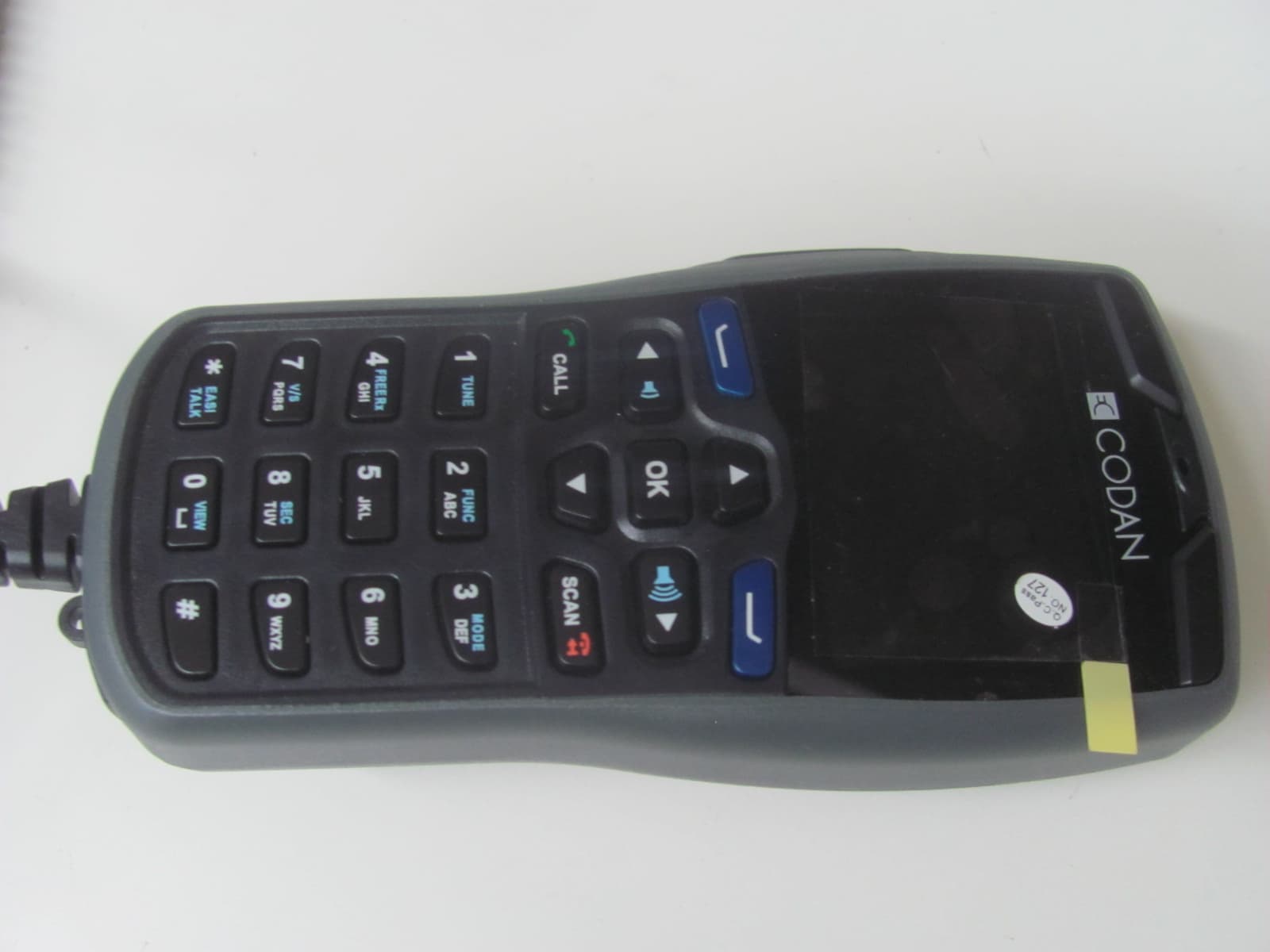
DYY2210
Jun 10, 20132210 HF Radio System
Equipment Class
TNB - Licensed Non-Broadcast Station Transmitter
DYYNGT-11
Jan 31, 2006HF SSB Transceiver
Equipment Class
TNB - Licensed Non-Broadcast Station Transmitter
DYYNGT-3
Jan 31, 2006TNB Licensed Non-Broadcast Station Transmitter
Equipment Class
TNB - Licensed Non-Broadcast Station Transmitter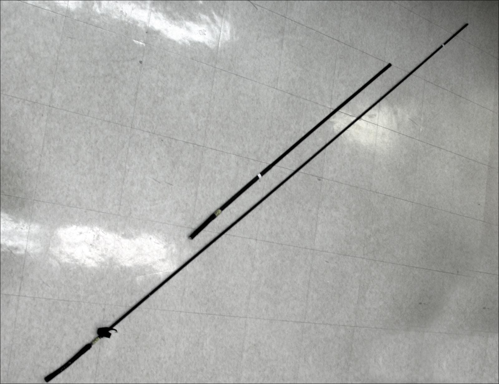
DYY2110
Mar 07, 20052110 SSB Transceiver
Equipment Class
TNB - Licensed Non-Broadcast Station Transmitter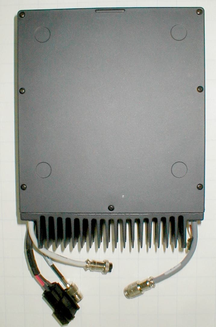
DYYNGT-2
Jun 23, 2003RF Transceiver
Equipment Class
TNB - Licensed Non-Broadcast Station Transmitter