DYYNGT-2RF Transceiver
Codan Limited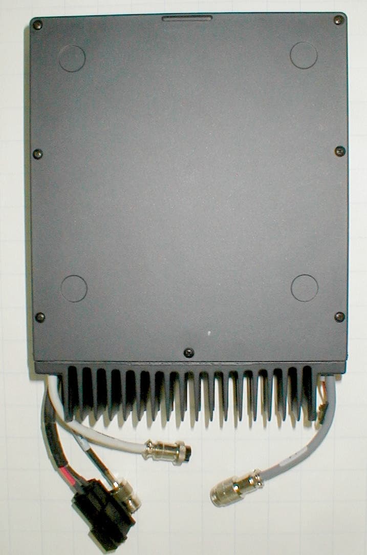
Click to zoom
Application Details
- Equipment Class
- TNB - Licensed Non-Broadcast Station Transmitter
- Date of Grant
- Jun 23, 2003
- Application Purpose
- Original Equipment
- Date of Application
- Jun 23, 2003
- Equipment Note
- RF Transceiver
- Frequency Range
- 25.00000000 - 30.00000000
- Company
- Codan Limited
- Country
- Australia
Documents & Files
Document Text
Text extracted from the exhibit documents filed with the FCC. Open a document above to read the original.
Cover Letter(s)
American Telecommunications Certification Body Inc. 6731 Whittier Ave, McLean, VA 22101 June 6, 2003 RE: FCC ID: DYYNGT-2_ATCB000491 Attention: Gregory M. Snyder / Brian J. Dettling I have a few comments on this Application. 1. Please note that while I may make assumptions as to how and where you derived the 84.4dBuV limit for 1.65MHz fundamental spurious emissions, the report needs to clearly identify the derivation and calculation of this limit. 2. Please note that the power output listed in the report for the range between 1.6MHz and 25MHz is 108watts. The power output listed for the 25 to 30MHz range is 117.5watts. Please note that the power on the grant for licensed devices is to be the measured power not the rated power. The 731 states the rated power. Please provide a 731 showing the frequency split in the range 1.6 to 25MHz and 25 MHz to 30 MHz (frequency tolerances are different in these ranges), and please provide a 731 with the measured power levels. 3. Please note that you have not justified the emissions designators. This can be done by calculation or sometimes by OBW measurements. Since you have not provided the calculation of the emissions designators, evidence in OBW plots showing justification for the three emissions designators listed on the 731 needs to be provided. I might be able to accept the J3E and H3E on the existing plot ( difference being H is with full carrier and J is suppressed carrier), but I do not think this is justification enough for the J2B ( SSB with quantized digital info) Please provide evidence of the emissions designators. Alternately, please explain why the existing plot should be used for all three. Dennis Ward mailto:[email protected] The items indicated above must be submitted before processing can continue on the above referenced application. Failure to provide the requested information may result in application termination. Correspondence should be considered part of the permanent submission and may be viewed from the Internet after a Grant of Equipment Authorization is issued. Please do not respond to this correspondence using the email reply button. In order for your response to be processed expeditiously, you must submit your documents through the AmericanTCB.com website. Also, please note that partial responses increase processing time and should not be submitted. Any questions about the content of this correspondence should be directed to the sender.
Cover Letter(s)
Response to ATCB Comments FCC ID: DYYNGT-2 1 Washington Laboratories, Ltd. 7560 LINDBERGH DRIVE GAITHERSBURG, MD 20879 (301) 417 – 0220 FAX # (301) 417 - 9069 June 24, 2003 Mr. Dennis Ward American Telecommunications Certification Body Inc. 6731 Whittier Ave McLean, VA 22101 RE: Comments of June 6, 2003 APPLICATION: DYYNGT-2 Codan Limited Dear Mr. Ward: Below are the comments that you have provided regarding the application for certification referenced above. Our responses to those comments are in bold italic. Many responses refer you to additional exhibit(s) which has been uploaded to the application folder at the ATCB website. Thank you for your attention. Please feel free to contact us for any additional information that you may require. Regards, Gregory M. Snyder Chief EMC Engineer, Wireless/Telco Services Manager Brian J. Dettling Documentation Specialist WLL Project: 7314 June 6, 2003 RE: Codan Limited FCC ID: DYYNGT-2 1) Please note that while I may make assumptions as to how and where you derived the 84.4dBuV limit for 1.65MHz fundamental spurious emissions, the report needs to clearly identify the derivation and calculation of this limit. R. The test report has been amended in Section 4.5 to show the calculation to arrive at the 84.4 dBuV/m limit. Please see exhibit “NGT-2 Test Report Revision 1.pdf.” Response to ATCB Comments FCC ID: DYYNGT-2 2 2) Please note that the power output listed in the report for the range between 1.6MHz and 25MHz is 108watts. The power output listed for the 25 to 30MHz range is 117.5watts. Please note that the power on the grant for licensed devices is to be the measured power not the rated power. The 731 states the rated power. Please provide a 731 showing the frequency split in the range 1.6 to 25MHz and 25 MHz to 30 MHz (frequency tolerances are different in these ranges), and please provide a 731 with the measured power levels. R. The 731 has been corrected to show the measured powers and the split frequency ranges. Please see exhibit “NGT-2 Form 731 Revised.pdf.” 3) Please note that you have not justified the emissions designators. This can be done by calculation or sometimes by OBW measurements. Since you have not provided the calculation of the emissions designators, evidence in OBW plots showing justification for the three emissions designators listed on the 731 needs to be provided. I might be able to accept the J3E and H3E on the existing plot (difference being H is with full carrier and J is suppressed carrier), but I do not think this is justification enough for the J2B (SSB with quantized digital info) Please provide evidence of the emissions designators. Alternately, please explain why the existing plot should be used for all three. R. Measurements of OBW have been performed using the SELCALL 2 tone FSK function of the radio to show the J2B emission designator. Plots have been added to the revised test report in Section 4.3. Please see exhibit “NGT-2 Test Report Revision 1.pdf.”
External Photos
Overall View NGT-2 Transceiver Handset External Speaker Junction Box Top View Bottom View Side View Front View Rear View
ID Label/Location Info
RF-Unit NGT SR Serial No. Type 2010 Australia FCC ID DYYNGT-2 RF-Unit NGT VRSerial No. Type 2010 Australia FCC ID DYYNGT-2
Internal Photos
Top – Cover Removed Top Boards – Shield Removed Top Boards – Top View Top Boards – Bottom View Top View of Housing – Boards Removed Bottom – Cover Removed Bottom – Shields Removed Bottom Boards – Top View Bottom Boards – Bottom View Bottom View of Housing – Boards Removed
Operational Description
Theory of Operation This document is an excerpt from the NGT Transceiver System Technical Service Manual, Chapter 4. NGT Transceiver System Technical Manual 4-1 Transmit Path Handset microphone amplifier transmit path Drawing 04-03125 The handset has an electret microphone. When PTT (press-to-talk) is not pressed, the microphone audio is clamped by V5. When PTT is Pressed, V5 is turned off, allowing audio from the microphone to be passed to the amplifier IC9/B. The output of IC9/B is split into two paths, one going to the handset audio bus, the other passing through the inverter IC9/A before going to the handset audio bus. In this way, push-pull balanced audio is provided to the junction box via the handset. Junction box transmit path Drawing 04-03201 The junction box has four transmit audio inputs. These four inputs are mixed together at the input of IC7/A as described below. Tx Audio Input 1. When PTT is pressed on the handset, the handset audio AIN+ and AIN- on P7 is passed to IC11/A. IC11/A converts the balanced audio to single-ended audio that is then passed to IC7/A. Tx Audio Input 2. When PTT is pressed on the desk console, the desk console audio is mixed via R57 at the input of IC7/A. Tx Audio Input 3. The audio input of the GPIO port is on pin 5 and 15 of J107. When the GPIO PTT is active, the audio is balanced via T1 before passing to the volume control IC2/C. IC2/C is activated to a preset level, controlled by software. The audio is then mixed via R58 at the input of IC7/A. Tx Audio Input 4. A tone used for Morse is generated by IC9 on the Microprocessor PCB (drawing 04-03133). The tone is passed to the tone volume control IC2/B before mixing via R56 at the input of IC7/A. The output of IC7/A goes to IC11/B and then to IC10/A. These two ICs from a three-pole low- pass anti-aliasing filter with a nominal 3kHz cut-off frequency. The output of IC10/A passes to IC10/B. IC10/B acts as a peak limiter due to H2 and H3 in the feedback path. The normal level for the audio is 1 V P-P. Where the audio level is much higher than this (such as when someone shouts into the microphone), IC10/B limits the output of IC10/A to 4 V P-P. This protects the synchronization pulse generated in the RF unit from becoming corrupted. The output of IC10/B is split into two paths, one going to the TDM gate IC9/B, the other passing through the inverter IC8/B before going to the TDM gate IC9/A. This produces push-pull balanced audio. NGT Transceiver System Technical Manual 4-2 Time division multiplex audio channels Drawing 04-03201 The system audio uses TDM to produce seven channels of audio and one synchronisation pulse to reference the channel timing. The audio is sampled at a rate of 12.5 kHz by the TDM gates IC9/A and IC9/B. IC9/A and IC9/B are driven by IC1. The position of the audio channel will vary depending on the requirements of the system. Its position can be determined by attaching an oscilloscope at test point 2 (TP2). Figure 4 – 1: Representation of the waveform as measured at test point 2 (TP2) IC11 on the Audio Interface PCB (drawing 04-03109) in the RF unit, drives V3 and IC6/A to generate the synchronization pulse. The TDM audio from TDM gates IC9/A and IC9/B is passed to the RF unit via SYS AUDIO+- on the CIB. Codan Interconnect Bus transmit path The CIB is an 8-wire bus that connects all the units in the system together: • SYS AUDIO (+-): The audio is TDM balanced, as described in the previous section. • SYS DATA (+-): The data uses Control Area Network (CAN) protocol. This protocol has good error detection capabilities and performs well in high noise environments. The data rate on the CIB is 100 kbps. • STBY: Standby power is a 100mA 5 V DC continuous supply. This is used to backlight the ON/OFF button at night. • PROTECTED A: The Protected A rail is an unregulated battery supply that is used to supply power to all the units in the transceiver system. The maximum current that this can supply is 2 A. If very long runs of the CIB cabling are required, an external supply may be connected to the junction box to supply power locally. • PWR ON: The Power On line is used to switch the transceiver on when it is grounded as described in the Power On section at the beginning of this chapter. NGT Transceiver System Technical Manual 4-3 • GND: Ground is the supply return wire and is connected to the negative terminal of the battery. RF unit-Audio Interface PCB transmit path Drawing 04-03109 The Transmit TDM audio from the CIB goes to IC7/B. IC7/B then converts the push-pull audio to single-ended audio so that the correct audio channel is sampled by IC6/D. C21 is the hold capacitor, and IC7/A, IC8/A and IC8/B form a 5-pole Chebishev re-construction filter with a nominal cutoff frequency of 3 kHz. The filtered audio then goes to the Application Processor PCB via ADC AUX IN. RF unit-Application Processor PCB transmit path Drawing 04-03109 The Transmit audio goes to IC5, pin 28. This audio interface device contains an analog to digital converter and a digital to analog converter. The analog Transmit audio is sampled and converted by IC5 into digital format. A compression function is applied to the digital audio as shown in Figure 4-2 below. Figure 4-2: Representation of compression function by IC5 The decay time constant is controlled by software and can be varied depending on the type of transmission. For example, for speech, the time constant needs to be short, but for data it needs to be lengthened to improve the bit error rate (BER). The output level is halved when amplitude modulation (AM) is transmitted or low power is selected, and is controlled by software. The output of IC5, pins 3 and 4, are summed together in IC7/A to produce an output of 1 V P-P. This output then goes via the Audio Interface PCB to the Rx/Exciter PCB. NGT Transceiver System Technical Manual 4-4 RF unit-Rx/Exciter PCB transmitter exciter Transmit/Receive switching Drawing 04-03106 sheet 3 The PTT command from the handset via …
Text truncated - open the document above for the full version.
Test Report
Document 7314-01, Rev. 1 FCC ID: DYYNGT-2 FCC Certification Test Report Washington Laboratories, Ltd April 2003 FCC Certification Test Report for Codan Limited DYYNGT-2 April 25, 2003 Revision 1 June 24, 2003 Prepared for: Codan Limited 81 Graves Street Newton, South Australia 5074 AUSTRALIA Prepared By: Washington Laboratories, Ltd. 7560 Lindbergh Drive Gaithersburg, Maryland 20879 FCC Certification Test Report Document 7314-01, Rev. 1 FCC ID: DYYNGT-2 FCC Certification Test Report Washington Laboratories, Ltd April 2003 FCC Certification Test Program FCC Certification Test Report for the Codan Limited NGT Transceiver DYYNGT-2 April 17, 2003 Revision 1 June 24, 2003 WLL JOB# 7314 Prepared by: Brian J. Dettling Documentation Specialist Reviewed by: Gregory M. Snyder Chief EMC Engineer Document 7314-01, Rev. 1 FCC ID: DYYNGT-2 FCC Certification Test Report Washington Laboratories, Ltd April 2003 ii Abstract This report has been prepared on behalf of Codan Limited to support the attached Application for Equipment Authorization under Part 90 of the FCC Rules and Regulations. This Federal Communication Commission (FCC) Certification Test Report documents the test configuration and test results for a Codan Limited NGT SSB Transceiver. Testing was performed on an Open Area Test Site (OATS) of Washington Laboratories, Ltd, 7560 Lindbergh Drive, Gaithersburg, MD 20879. Site description and site attenuation data have been placed on file with the FCC's Sampling and Measurements Branch at the FCC laboratory in Columbia, MD. Washington Laboratories, Ltd. has been accepted by the FCC and approved by NIST NVLAP (NVLAP Lab Code: 200066-0) as an independent FCC test laboratory. The Codan Limited NGT SSB Transceiver complies with the technical requirements of Part 90 of the FCC Rules and Regulations. Revision 1 June 24, 2003 Document 7314-01, Rev. 1 FCC ID: DYYNGT-2 FCC Certification Test Report Washington Laboratories, Ltd April 2003 iii Table of Contents Abstract......................................................................................................ii 1 Introduction...............................................................................................................1 1.1 Compliance Statement............................................................................................1 1.2 Test Scope............................................................................................................1 1.3 Contract Information..............................................................................................1 1.4 Test Dates.............................................................................................................1 1.5 Test and Support Personnel....................................................................................1 1.6 Abbreviations.........................................................................................................2 2 Equipment Under Test................................................................................................3 2.1 EUT Identification & Description............................................................................3 2.2 Test Configuration..................................................................................................3 2.3 Test Location.........................................................................................................4 2.4 Measurements........................................................................................................4 2.4.1 References.....................................................................................................4 2.5 Measurement Uncertainty.......................................................................................4 3 Test Equipment..........................................................................................................6 4 Test Results...............................................................................................................7 4.1 RF Power Output: (FCC Part §2.1046).................................................................7 4.2 Modulation Characteristics: (FCC Part §2.1047); Audio Frequency Response........7 4.3 Emission Mask and Occupied Bandwidth: (FCC Part §2.1049)............................10 4.4 Spurious Emissions at Antenna Terminals (FCC Part §2.1051...............................14 4.5 Radiated Spurious Emissions: (FCC Part §2.1053)...............................................18 4.5.1 Test Procedure..........................................................................................18 4.6 Frequency Stability: (FCC Part §2.1055).............................................................21 Document 7314-01, Rev. 1 FCC ID: DYYNGT-2 FCC Certification Test Report Washington Laboratories, Ltd April 2003 iv List of Tables Table 1. Device Summary....................................................................................................3 Table 2. Interface Cables.....................................................................................................4 Table 3: Test Equipment List................................................................................................6 Table 4. RF Power Output...................................................................................................7 Table 5: Radiated Emission Test Data, Channel 3 29.9 MHz...............................................19 Table 6: Radiated Emission Test Data, Channel 2 15.6 MHz...............................................20 Table 7: Radiated Emission Test Data, Channel 1 1.65 MHz...............................................21 Table 8. Frequency Deviation as a Function of Temperature................................................22 Table 9. Frequency Deviation as a Function of Voltage.......................................................23 List of Figures Figure 4-1. Audio Frequency Response.................................................…
Text truncated - open the document above for the full version.
Test Setup Photos
Emissions Testing Configuration Temperature Stability Test Configuration
Contact Information
Applicant
Bruce Johnson(RF Design Engineer)
Technical Contact
Washington Laboratories, Ltd.Gregory M Snyder
[email protected]301/ 417-0220
7560 Lindbergh Drive · Gaithersburg, Maryland · United States
Technical Specifications
| # | Rule Parts | Frequency Range | Power Output | Emission | Tolerance |
|---|---|---|---|---|---|
| 6 | 9 | 25 MHz - 30 MHz | 117.5 W | 2K80J2B | 20 ppm |
Other Applications from Codan Limited
DYY2410
Feb 24, 20202410 ManPack HF Transceiver
Equipment Class
TNB - Licensed Non-Broadcast Station Transmitter
DYY2210
Jun 10, 20132210 HF Radio System
Equipment Class
TNB - Licensed Non-Broadcast Station Transmitter
DYYNGT-11
Jan 31, 2006HF SSB Transceiver
Equipment Class
TNB - Licensed Non-Broadcast Station Transmitter
DYYNGT-3
Jan 31, 2006TNB Licensed Non-Broadcast Station Transmitter
Equipment Class
TNB - Licensed Non-Broadcast Station Transmitter
DYY2110
Mar 07, 20052110 SSB Transceiver
Equipment Class
TNB - Licensed Non-Broadcast Station Transmitter