DYYNGT-1RF Transceiver
Codan Limited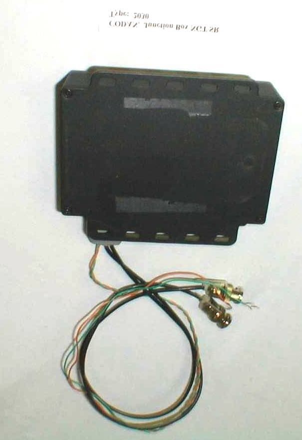
Click to zoom
Application Details
- Equipment Class
- TNB - Licensed Non-Broadcast Station Transmitter
- Date of Grant
- Feb 07, 2001
- Application Purpose
- Original Equipment
- Date of Application
- Dec 18, 2000
- Equipment Note
- RF Transceiver
- Frequency Range
- 25.00000000 - 30.00000000
- Company
- Codan Limited
- Country
- Australia
Documents & Files
Document Text
Text extracted from the exhibit documents filed with the FCC. Open a document above to read the original.
Cover Letter(s)
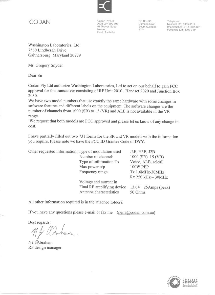
Washington Laboratories, Ltd. 7560 Lindbergh Drive Gaithersburg, MD 20879 December 19, 2000 Mr. Frank Coperich Federal Communicatio ns Co mmission 7435 Oakland Mills Road Columbia, MD 20146 Dear Mr. Coperich, This application for submission (FCC ID: DYYNGT-1) is being submitted to replace the current application under FCC ID: DYYNGT. We ask that the original application be “Set Aside” (AS). This request is based on the e-mail response received from your office on 11/9/00. The e-mail has been included below in italics for your reference. All information has remained unchanged from the original application with the exception of the following items: 1. The FCC ID has been c ha nged to DYYNGT-1. 2. New data has recorded in the test report for frequency stability. 3. New Occupied BW and Emission Mask data is included in the updated test report. Best regards, Gregor y M. S nyder Chief EMC Engi neer Washington Laboratories, Ltd. 301/417-0220 [email protected] From: Frank Coperich [[email protected]] Sent: Thursday, November 09, 2000 8:32 AM To: Rich Fabina; [email protected] Subject: Re: Amendment to Test Report This is a reply: The file under the original EA # cannot be changed (now). The only option is to ask for the original application to be "Set Aside" (AS) and then get a new Grant with a new FCC ID. Without the "AS" all of the original data would be viewable. A Permissive Change is not an option since they want to change the frequency stability rating. Plus any Permissive Change is filed under a different EA #. >>> "Greg Snyder" <[email protected]> 11/01/00 04:11PM >>> Dear Mr. Fabina, Our client (Codan Pty Ltd, FCC ID: DYYNGT) has requested an amendment to the test report which was submitted for FCC Certification. This request is made based on data that is reported in the test report which could have commercial ramifications to Codan. The data reported meets the requirements for FCC Certification, however, Codan has tighter specifications which they advertise as features. The tests that are impacted are the Occupied Bandwidth/Emission Mask and the Frequency Stability tests. We have maintained the same unit used in the original testing and have retaken the data for these tests with improved results. The reason for the improved test results are due to the following two items: 1)for the Frequency Stability test, the unit was in SSB mode and therefore background noise was causing the frequency to shift slightly during the original testing. 2)for the Occupied Bandwidth/Emissions Mask test, the 2 tones used for modulation contained large harmonic content which distorted the actual output but within the specified FCC limits. Our question is; can we update the test report and submit the new test report as a Class II Permissive change to supersede the original test report? Thank you for your consideration of this request. Best Regards, Greg Snyder Chief EMC Engineer [email protected] Washington Laboratories, Ltd. Phone:(301) 417-0220 Fax:(301) 417-9069
External Photos
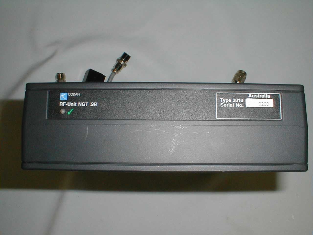
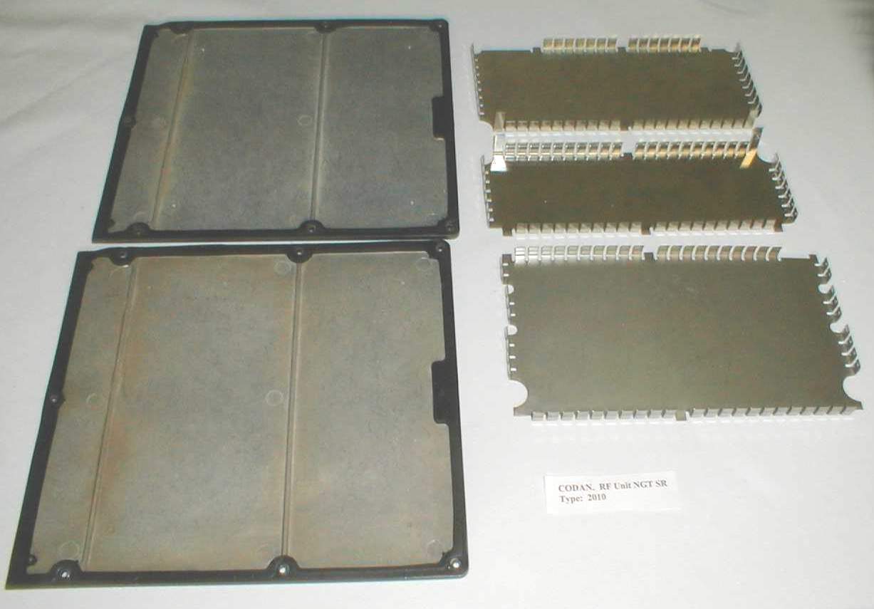
Radio System Hand Held Unit – Front Hand Held Unit – Back Junction Box – Top Junction Box – Bottom Junction Box – Back RF Unit – Top RF Unit – Bottom RF Unit – Back
ID Label/Location Info
FCC ID: DYYNGT-1
Operational Description
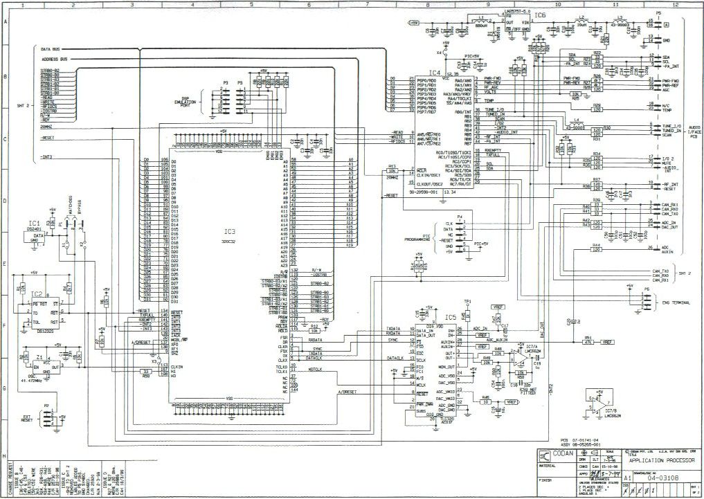
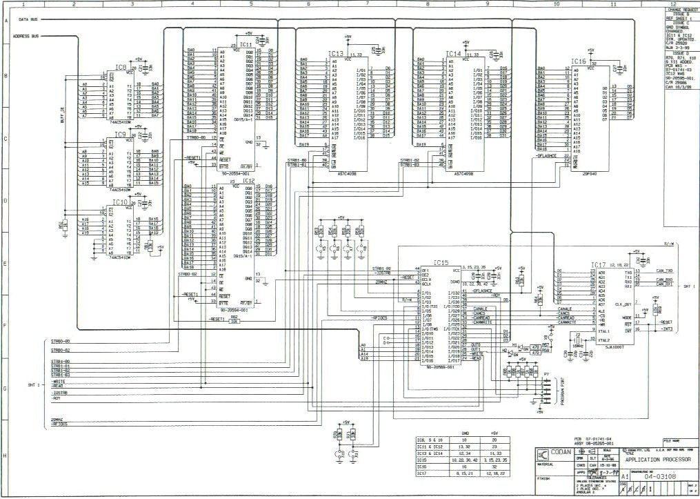
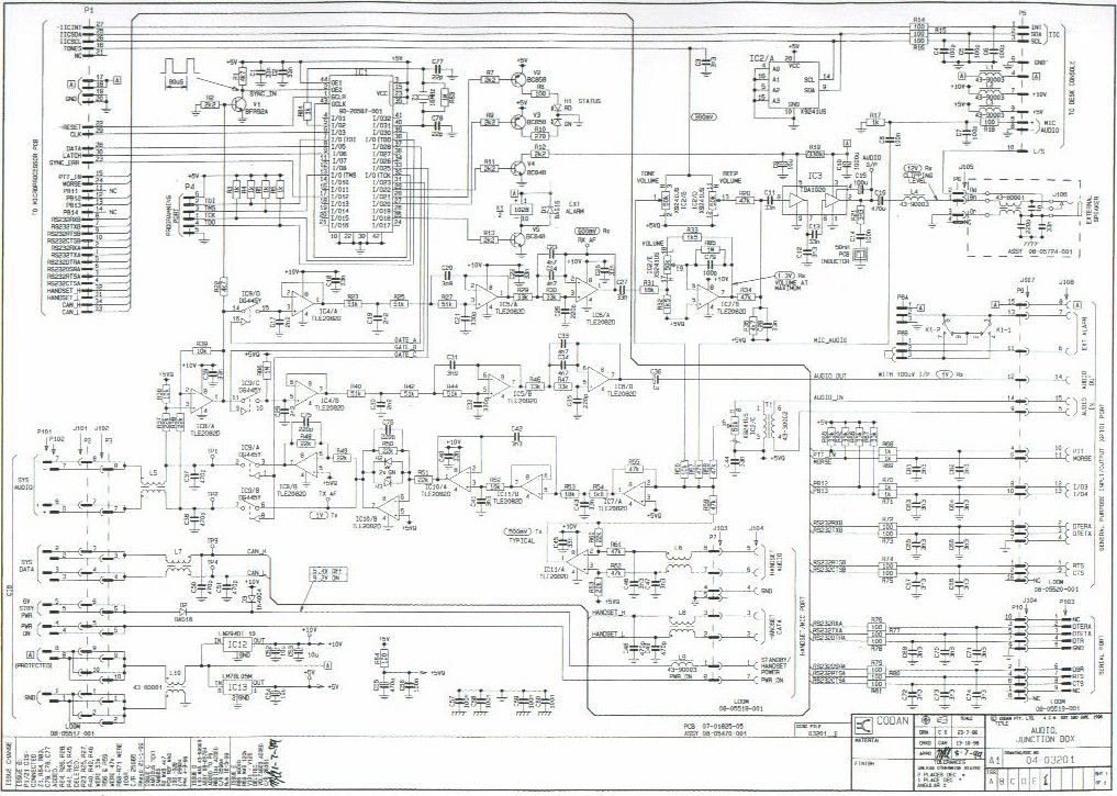
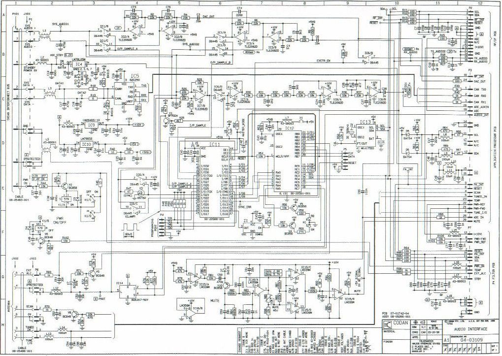
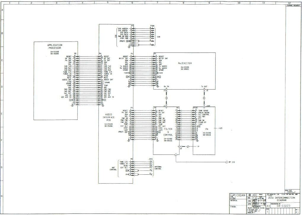
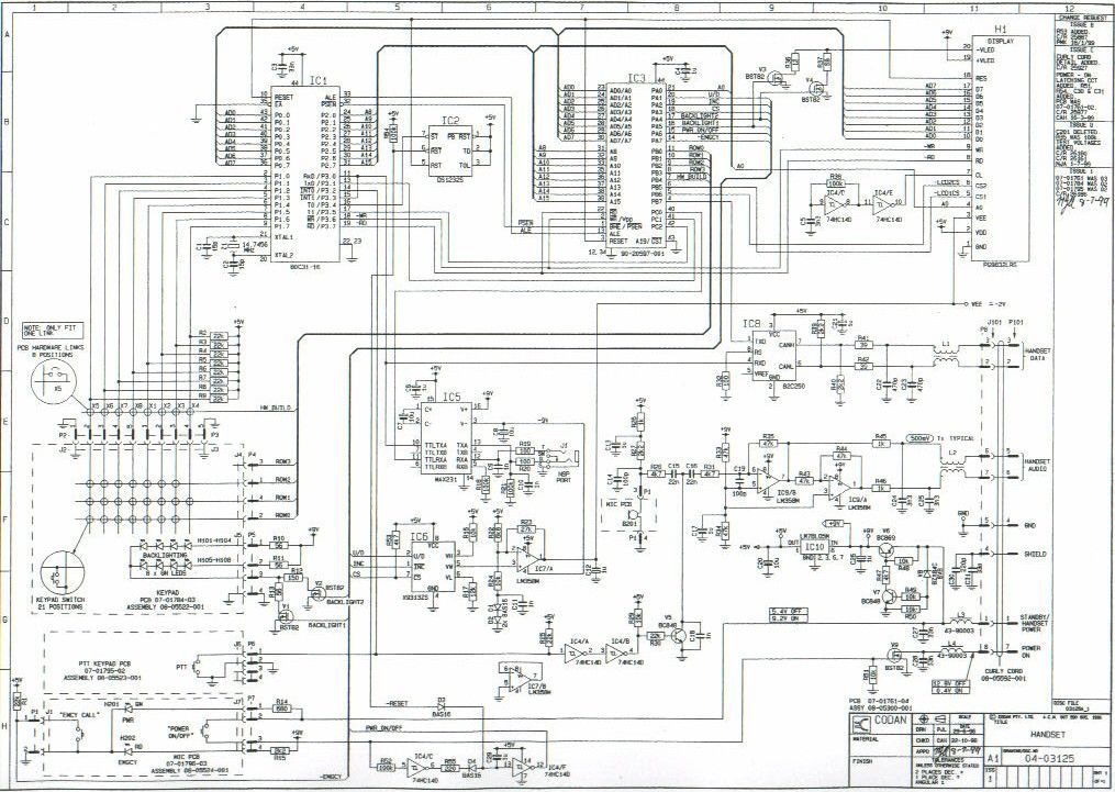
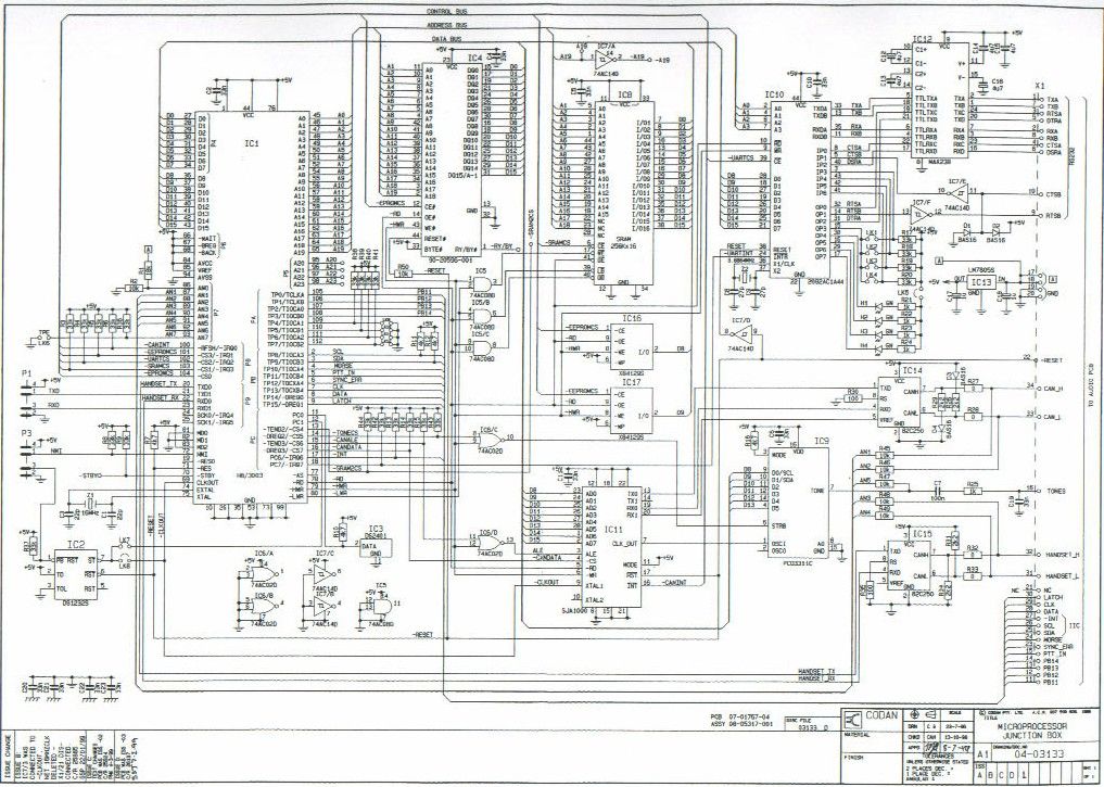
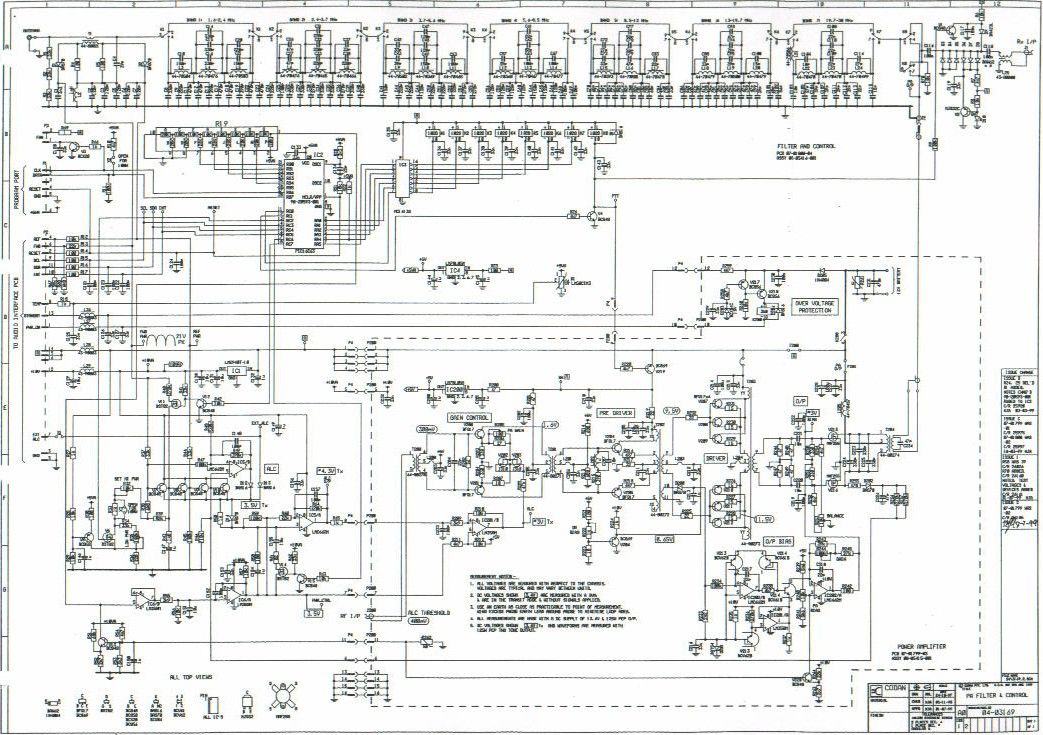
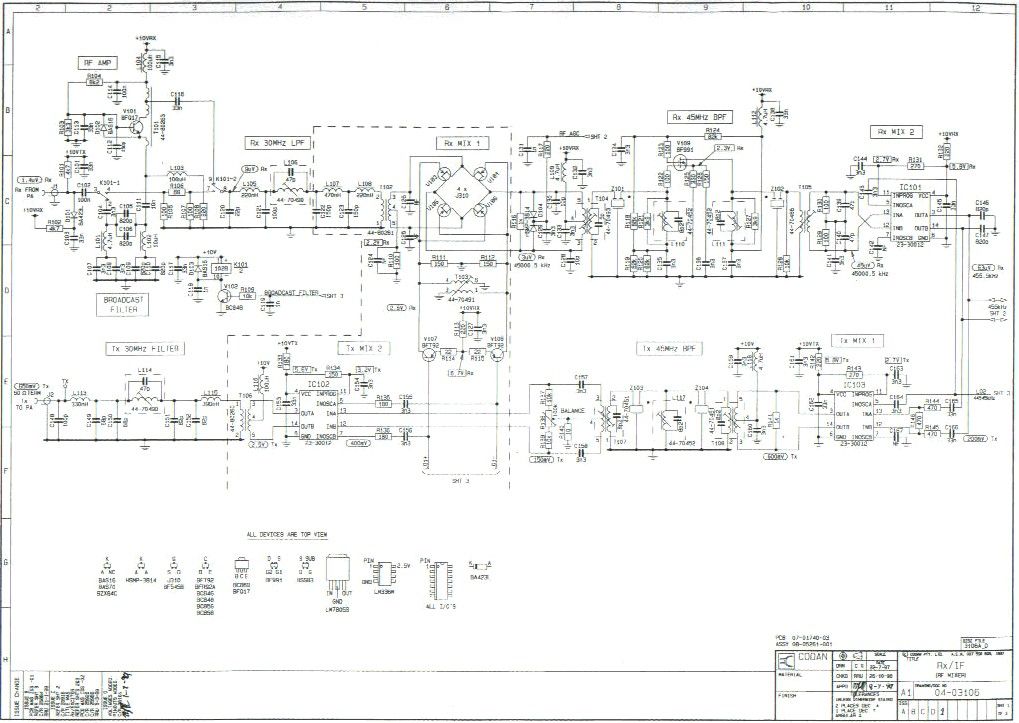
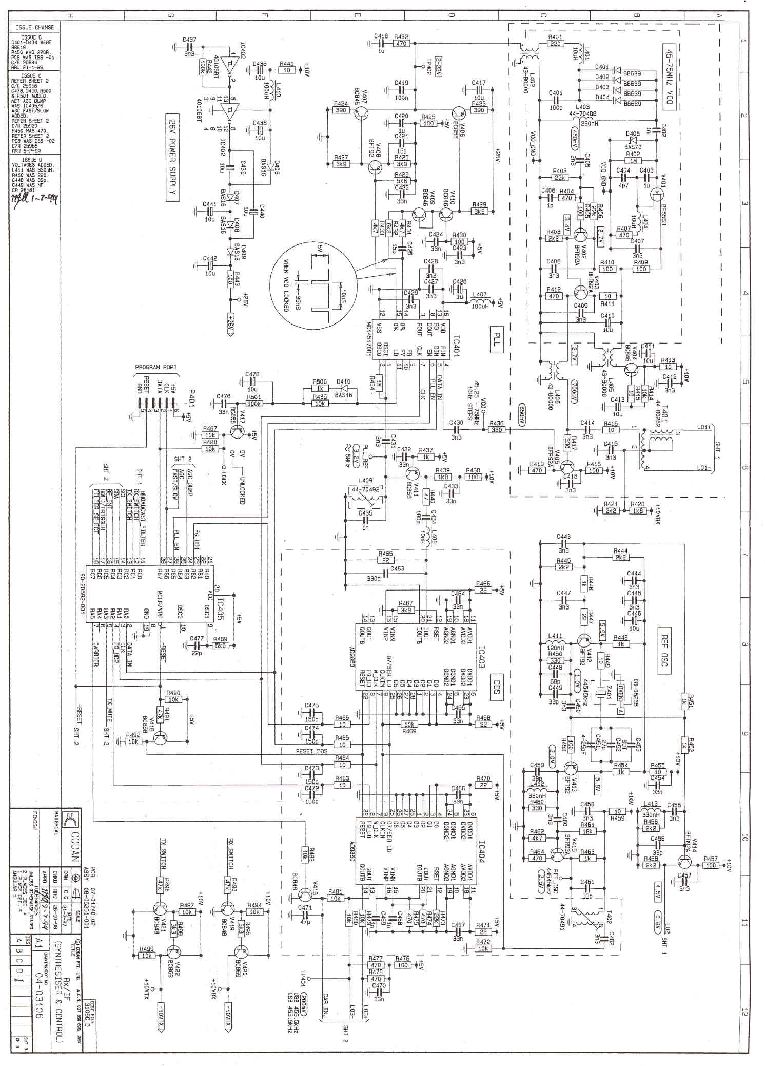
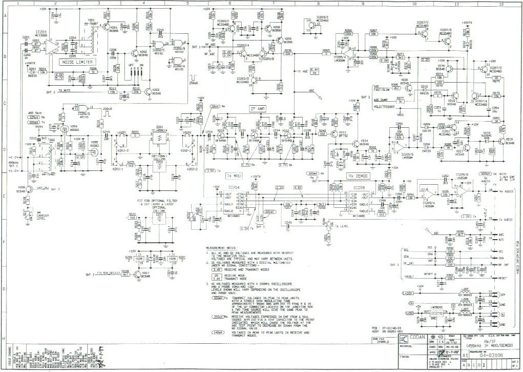
Theory of Operation This document is an excerpt from the NGT Transceiver System Technical Service Manual, Chapter 4. NGT Transceiver System Technical Manual 4-1 Transmit Path Handset microphone amplifier transmit path Drawing 04-03125 The handset has an electret microphone. When PTT (press-to-talk) is not pressed, the microphone audio is clamped by V5. When PTT is Pressed, V5 is turned off, allowing audio from the microphone to be passed to the amplifier IC9/B. The output of IC9/B is split into two paths, one going to the handset audio bus, the other passing through the inverter IC9/A before going to the handset audio bus. In this way, push-pull balanced audio is provided to the junction box via the handset. Junction box transmit path Drawing 04-03201 The junction box has four transmit audio inputs. These four inputs are mixed together at the input of IC7/A as described below. Tx Audio Input 1. When PTT is pressed on the handset, the handset audio AIN+ and AIN- on P7 is passed to IC11/A. IC11/A converts the balanced audio to single-ended audio that is then passed to IC7/A. Tx Audio Input 2. When PTT is pressed on the desk console, the desk console audio is mixed via R57 at the input of IC7/A. Tx Audio Input 3. The audio input of the GPIO port is on pin 5 and 15 of J107. When the GPIO PTT is active, the audio is balanced via T1 before passing to the volume control IC2/C. IC2/C is activated to a preset level, controlled by software. The audio is then mixed via R58 at the input of IC7/A. Tx Audio Input 4. A tone used for Morse is generated by IC9 on the Microprocessor PCB (drawing 04-03133). The tone is passed to the tone volume control IC2/B before mixing via R56 at the input of IC7/A. The output of IC7/A goes to IC11/B and then to IC10/A. These two ICs from a three-pole low- pass anti-aliasing filter with a nominal 3kHz cut-off frequency. The output of IC10/A passes to IC10/B. IC10/B acts as a peak limiter due to H2 and H3 in the feedback path. The normal level for the audio is 1 V P-P. Where the audio level is much higher than this (such as when someone shouts into the microphone), IC10/B limits the output of IC10/A to 4 V P-P. This protects the synchronization pulse generated in the RF unit from becoming corrupted. The output of IC10/B is split into two paths, one going to the TDM gate IC9/B, the other passing through the inverter IC8/B before going to the TDM gate IC9/A. This produces push-pull balanced audio. NGT Transceiver System Technical Manual 4-2 Time division multiplex audio channels Drawing 04-03201 The system audio uses TDM to produce seven channels of audio and one synchronisation pulse to reference the channel timing. The audio is sampled at a rate of 12.5 kHz by the TDM gates IC9/A and IC9/B. IC9/A and IC9/B are driven by IC1. The position of the audio channel will vary depending on the requirements of the system. Its position can be determined by attaching an oscilloscope at test point 2 (TP2). Figure 4 – 1: Representation of the waveform as measured at test point 2 (TP2) IC11 on the Audio Interface PCB (drawing 04-03109) in the RF unit, drives V3 and IC6/A to generate the synchronization pulse. The TDM audio from TDM gates IC9/A and IC9/B is passed to the RF unit via SYS AUDIO+- on the CIB. Codan Interconnect Bus transmit path The CIB is an 8-wire bus that connects all the units in the system together: • SYS AUDIO (+-): The audio is TDM balanced, as described in the previous section. • SYS DATA (+-): The data uses Control Area Network (CAN) protocol. This protocol has good error detection capabilities and performs well in high noise environments. The data rate on the CIB is 100 kbps. • STBY: Standby power is a 100mA 5 V DC continuous supply. This is used to backlight the ON/OFF button at night. • PROTECTED A: The Protected A rail is an unregulated battery supply that is used to supply power to all the units in the transceiver system. The maximum current that this can supply is 2 A. If very long runs of the CIB cabling are required, an external supply may be connected to the junction box to supply power locally. • PWR ON: The Power On line is used to switch the transceiver on when it is grounded as described in the Power On section at the beginning of this chapter. NGT Transceiver System Technical Manual 4-3 • GND: Ground is the supply return wire and is connected to the negative terminal of the battery. RF unit-Audio Interface PCB transmit path Drawing 04-03109 The Transmit TDM audio from the CIB goes to IC7/B. IC7/B then converts the push-pull audio to single-ended audio so that the correct audio channel is sampled by IC6/D. C21 is the hold capacitor, and IC7/A, IC8/A and IC8/B form a 5-pole Chebishev re-construction filter with a nominal cutoff frequency of 3 kHz. The filtered audio then goes to the Application Processor PCB via ADC AUX IN. RF unit-Application Processor PCB transmit path Drawing 04-03109 The Transmit audio goes to IC5, pin 28. This audio interface device contains an analog to digital converter and a digital to analog converter. The analog Transmit audio is sampled and converted by IC5 into digital format. A compression function is applied to the digital audio as shown in Figure 4-2 below. Figure 4-2: Representation of compression function by IC5 The decay time constant is controlled by software and can be varied depending on the type of transmission. For example, for speech, the time constant needs to be short, but for data it needs to be lengthened to improve the bit error rate (BER). The output level is halved when amplitude modulation (AM) is transmitted or low power is selected, and is controlled by software. The output of IC5, pins 3 and 4, are summed together in IC7/A to produce an output of 1 V P-P. This output then goes via the Audio Interface PCB to the Rx/Exciter PCB. NGT Transceiver System Technical Manual 4-4 RF unit-Rx/Exciter PCB transmitter exciter Transmit/Receive switching Drawing 04-03106 sheet 3 The PTT command from the handset via …
Text truncated - open the document above for the full version.
Test Report
FCC CERTIFICATION TEST REPORT prepared for Codan Proprietary Ltd. PO Box 96 Campbelltown, South Australia 5074 Australia FCC ID: DYYNGT-1 December 18, 2000 WLL PROJECT #: 5337H This report shall not be reproduced, except in full, without the prior written consent of Washington Laboratories, Ltd. Codan PTY Ltd. FCC ID: DYYNGT-1 WLL Project No.: 5737X i TABLE OF CONTENTS STATEMENT OF QUALIFICATIONS 1.0 INTRODUCTION ........................................................................................................................................... 1 1.1 S UMMARY .............................................................................................................................................................. 1 2.0 DESCRIPTION OF EQUIPMENT UNDER TEST (EUT) ............................................................. 2 3.0 TEST CONFIGURATION ........................................................................................................................... 2 3.1 RF O UTPUT P OWER (FCC R ULE P ART 2.1046) ...................................................................................................... 2 3.2 M ODULATION C HARACTERISTICS (FCC R ULE P ART 2.1047).................................................................................. 3 3.3 O CCUPIED B ANDWIDTH (FCC R ULE P ART 2.1049) ................................................................................................ 3 3.5 R ADIATED E MISSIONS T ESTIN G (FCC R ULE P ART 2.1053)..................................................................................... 4 3.5.1 Radiated Data Reduction and Reporting ...................................................................................................... 4 3.6 F REQUENCY S TABILITY (FCC R ULE P ART 2.1055) ................................................................................................. 8 3.6 F REQUENCY S TABILITY (FCC R ULE P ART 2.1055) ................................................................................................. 8 3.6.1Frequency Stability for Voltage Variation............................................................................................ 8 3.6.2 Frequency Stability for Temperature Variation.................................................................................... 8 TABLES Table 1. Radiated Emissions Data Table 2. Measurement Equipment Used APPENDICES Appendix A.Modulation Characteristics Appendix B.Occupied Bandwidth Plots Appendix C.Spurious Emissions at Antenna Terminals Plots Appendix D.Statement of Measurement Uncertainty Codan PTY Ltd. FCC ID: DYYNGT-1 WLL Project No.: 5737X ii Codan PTY Ltd. FCC ID: DYYNGT-1 WLL Project No.: 5737X 1 FCC CERTIFICATION REPORT for Codan Proprietary Ltd. 1.0 Introduction This report has been prepared on behalf of Codan Proprietary Ltd. in support of their application for FCC Certification under Part 90 of the FCC Rules and Regulations. The Equipment Under Test was the NGT Transceiver (HF Transceiver) All measurements were performed at Washington Laboratories, Ltd. test center in Gaithersburg, MD. Site description and site attenuation data have been placed on file with the FCC's Sampling and Measurements Branch at the FCC laboratory in Columbia, MD. Washington Laboratories has been accepted by the FCC and approved by NIST NVLAP (NVLAP Lab Code 200066-0) as an independent FCC test laboratory. Measurements were made on the Equipment Under Test in accordance with FCC Rule Part 2, specifically the requirements stipulated in: 2.1046 RF Power Output 2.1047 Modulation Characteristics 2.1049 Occupied Bandwidth 2.1051 Spurious Emissions at Antenna Terminals 2.1053 Field Strength of Spurious Radiation 2.1055 Frequency Stability All results reported herein relate only to the item tested. This report shall not be used to claim product endorsement by NVLAP or any agency of the US Government. The measurement uncertainty of the data contained herein is ± 2.3 dB. Refer to Appendix D for Statement of Measurement Uncertainty. 1.1 Summary The Codan Proprietary Ltd. NGT Transceiver complies with the technical requirements of Part 90 of the FCC Rules and Regulations. Codan PTY Ltd. FCC ID: DYYNGT-1 WLL Project No.: 5737X 2 2.0 Description of Equipment Under Test (EUT) The Codan NGT Transceiver is a SSB transceiver that can be installed in a vehicle or used as a base station. The NGT system is comprised of a 2020 Handset, 2030 Junction Box and the 2101 RF Unit. The handset is a hand-held device with a microphone, press-to-talk (PTT) button, display and keypad. Two models of the NGT 2010 are available. The models are identical, having the same hardware. The only difference between the two is software features. The VR only has 15 channels and ALE is not available. The Junction Box is a unit to w hich the handset, RF unit, speaker and related items are connected. The units are connected together via the use of the Codan Interconnect Bus (CIB). The following are the specifications of the unit. Frequency Range:1.6 MHz to 30 MHz. Modulation:SSB (J3E), H3E and J2B Type of information:Voice, ALE, selcall Number of Channels:1000 (SR), 15 (VR) Maximum Output Power:100 Watts PEP 3.0 Test Configuration During testing, the EUT was configured with a 2020 handset and speaker connected to the 2030 junction box which was connected to the NGT RF unit. The transmitter was tested at 1.6 MHz (low channel), 15.6 MHz (mid channel), and 29.9 MHz (high channel). I/O PortsI/O Cables 2-pin DC input cable adapter>1m unshielded, DC power source to EUT 6-pin DIN6 inch shielded, not used. 8-pin DIN>1 m shielded, Transceiver to junction box F-type RF output>1 m coaxial, Transceiver to load (RF) 3.1 RF Output Power (FCC Rule Part 2.1046) The output from the transmitter was connected to a 50dB attenuator and then to the input of a HP 8564E RF Spectrum Analyzer. The analyzer offset was adjusted to compensate for the 50dB attenuator. Two tones (500Hz and 2400Hz) with equal audio levels were provided and …
Text truncated - open the document above for the full version.
Contact Information
Applicant
Bruce Johnson(RF Design Engineer)
Technical Contact
Washington Laboratories, Ltd.Gregory M Snyder
[email protected]301/417-0220
7560 Lindbergh Drive · Gaithersburg, Maryland · United States
Non-Technical Contact
Washington Laboroatories, Ltd.Brian J Dettling
[email protected]301/417-0220
Test Firm
Washington Laboratories, Ltd.Michael Violette
Technical Specifications
| # | Rule Parts | Frequency Range | Power Output | Emission | Tolerance |
|---|---|---|---|---|---|
| 6 | 9 | 25 MHz - 30 MHz | 100 W | 2K80J2B | 20 ppm |
Other Applications from Codan Limited
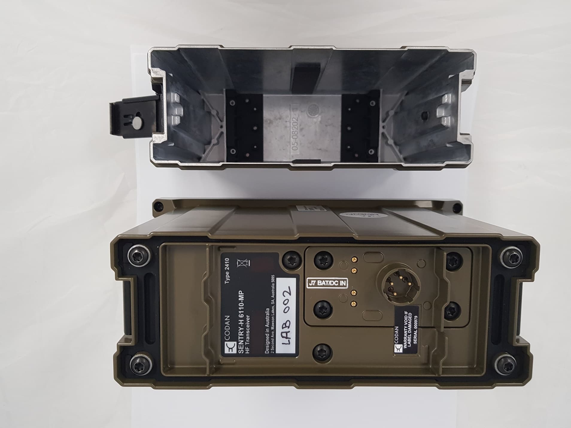
DYY2410
Feb 24, 20202410 ManPack HF Transceiver
Equipment Class
TNB - Licensed Non-Broadcast Station Transmitter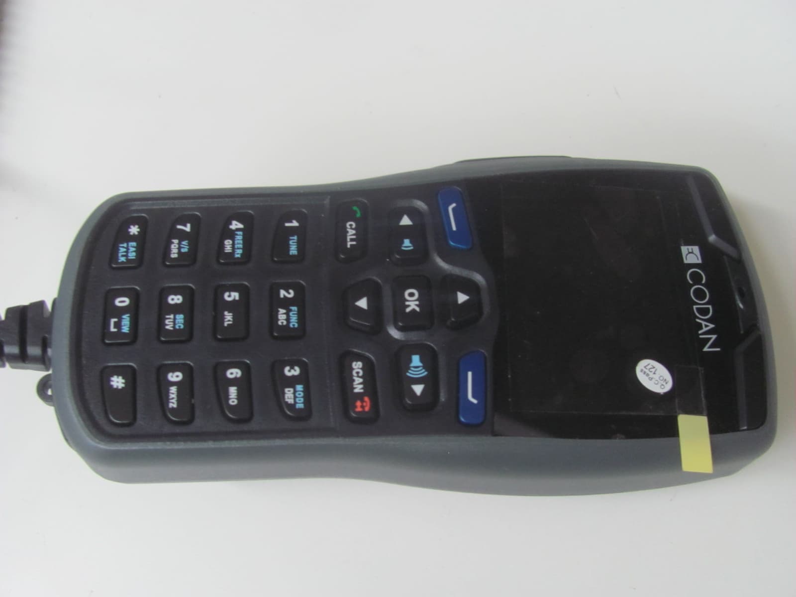
DYY2210
Jun 10, 20132210 HF Radio System
Equipment Class
TNB - Licensed Non-Broadcast Station Transmitter
DYYNGT-11
Jan 31, 2006HF SSB Transceiver
Equipment Class
TNB - Licensed Non-Broadcast Station Transmitter
DYYNGT-3
Jan 31, 2006TNB Licensed Non-Broadcast Station Transmitter
Equipment Class
TNB - Licensed Non-Broadcast Station Transmitter
DYY2110
Mar 07, 20052110 SSB Transceiver
Equipment Class
TNB - Licensed Non-Broadcast Station Transmitter