E4E6CYCIDV6400202Carrier ID Reader/Writer
Omron Corporation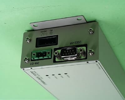
Click to zoom
Application Details
- Equipment Class
- DXX - Part 15 Low Power Communication Device Transmitter
- Date of Grant
- Jan 22, 2003
- Application Purpose
- Original Equipment
- Date of Application
- Jan 21, 2003
- Equipment Note
- Carrier ID Reader/Writer
- Frequency Range
- 0.13420000 - 0.13420000
- Company
- Omron Corporation
- Country
- Japan
Documents & Files
Document Text
Text extracted from the exhibit documents filed with the FCC. Open a document above to read the original.
Users Manual
SECTION 4 Reading from/Writing to ID Tags 63 CIDRW System User’s Manual SECTION 4 Reading from/Writing to ID Tags When SECS is Used64 When SECS is Not Used74 64 SECTION 4 When SECS is Used CIDRW System User’s Manual SECTION 4 Reading from/Writing to ID Tags When SECS is Used The SEMI standards are subject to revision: you must refer to the actual standards. • SEMI E99 THE CARRIER ID READER/WRITER FUNCTIONAL STANDARD • SEMI E5 EQUIPMENT COMMUNICATION STANDARD 2 MESSAGE CONTENT (SECS II) • SEMI E4 EQUIPMENT COMMUNICATION STANDARD 1 MESSAGE TRANSFER (SECS I) SECS Protocol Specifications Refer to page 113. Message Specifications List of Error Messages Refer to page 84. List of Messages Used ClassificationSFDirectionSECS II namesSee General purpose messages 11 S,H→E,replyAre You There Requestp.66 12 S,H←EOn Line Datap.66 CIDRW system messages 181S,H→E,replyRead Attribute Requestp.66 182S,H←ERead Attribute Datap.66 183S,H→E,replyWrite Attribute Requestp.67 184S,H←EWrite Attribute Acknowledgep.67 185S,H→E,replyRead Requestp.68 186S,H←ERead Data p.68 187S,H→E,replyWrite Requestp.69 188S,H←EWrite Acknowledgep.69 189S,H→E,replyRead ID Requestp.69 1810S,H←ERead ID Data p.69 1811S,H→E,replyWrite ID Requestp.70 1812S,H←EWrite ID Acknowledgep.70 1813S,H→E,replySubsystem Command Requestp.70 1814S,H←ESubsystem Command Acknowledgep.70 Data Item Dictionary SECS II data itemsNameFormatValue ATTRIDAttribute ID20Attribute name ATTRVALAttribute value20Attribute value MIDCarrier ID20All characters 00H-0FFH DATAData20All characters 00H-0FFH DATALENGTHDataSize52Data Segment Area Refer to page 48. DATASEGDataSeg20 STATUSPM information20"NE": Normally executed SSACKResult status20"NO": Normal "EE": Execution error *3 "CE": Communications error "HE": Hardware error *3 "TE": Tag error *3 65 CIDRW System User’s Manual SECTION 4 When SECS is Used SECTION 4 Reading from/Writing to ID Tags *1: "PS" is an expansion command for this unit. *2: When the TARGET ID is "00" (CIDRW), this is a zero length item. *3: "EE," "HE," and "TE" are used only with S18F6, S18F8, S18F10, and S18F12. S9F7 responses An S9F7 response is given when a message in an illegal format is received from the host device. "Illegal format" here means that there is a problem with the message composition, such as illegal attributes, or insuffi- cient or too many items. If other problems relating to the item contents arise, the response is SSACK = "CE" (commu- nications error). List of STATUSStatusL,4 1.<PMInformation> 2.<AlarmStatus> 3.<OperationalStatus> 4.<HeadStatus> *2 The STATUS values are included in the PM infor- mation. CPVALState request 20"OP", "MT", "PS" *1 TARGETIDTarget ID20"00"-"31" "00" indicates the CIDRW Controller itself. SSCMDSubsystem com- mands 20"ChangeState" "GetStatus" "PerformDiagnostics" "Reset" Data Item Dictionary SECS II data itemsNameFormatValue 66 SECTION 4 When SECS is Used CIDRW System User’s Manual SECTION 4 Reading from/Writing to ID Tags Specifications for Each Stream/Function • Online check • Get attributes S1,F1Are You There RequestS,H→E,reply Header only S1,F2On Line DataS,H←E L,2 1.<MDLN> 2.<SOFTREV> • Set MDLN (model number). • Set SOFTREV (software revision level). S18,F1Read Attribute RequestS,H→E,reply L,2 1.<TARGETID>"00"-"31" 2.L,n 1.<ATTRID1> ⋅ n.<ATTRIDn> • The setting for reading all attributes (CIDRW Controller or heads) is n = 0. S18,F2Read Attribute DataS,H←E L,4 1.<TARGETID>"00"-"31" 2.<SSACK> 3.L,n 1.<ATTRVAL1> ⋅ n.<ATTRVALn> 4.L,s 1.<STATUS1> ⋅ s.<STATUSs> • The order of the attribute data corresponds to the attribute ID specified by S18, F1. When reading of all attributes is specified, unsupported attribute items (ATTRVAL) are omitted. • When the specified target is invalid: n = 0, s = 0, SSACK = "CE" communications error • When one or more undefined attributes are included: n = 0, s = 0, SSACK = "CE" communications error • When head attributes are specified with TARGET = "00" or CIDRW Controller attributes are specified with TARGET <> "00": n = 0, s = 0, SSACK = "CE" communications error • If the status of SSACK is other than "NO" (normal), the List of Status will comprise zero items. 67 CIDRW System User’s Manual SECTION 4 When SECS is Used SECTION 4 Reading from/Writing to ID Tags • Set attributes F18,F3Write Attribute RequestS,H→E,reply L,2 1.<TARGETID>"00" (fixed) 2.L,n 1.L,2 1.<ATTRID1> 2.<ATTRVAL1> n.L,2 1.<ATTRIDn> 2,<ATTRVALn> Since the attributes for heads are all RO in this system, the target ID is fixed as "00". S18,F4Write Attribute AcknowledgeS,H←E L,3 1.<TARGETID>"00" (fixed) 2.<SSACK> 3.L,s 1.<STATUS1> ⋅ s.<STATUSs> • When the specified target is invalid: s = 0, SSACK = "CE" communications error • When one or more undefined attributes or RO attributes are included: s = 0, SSACK = "CE" communications error • When illegal attribute data is specified: s = 0, SSACK = "CE" communications error • If the status of SSACK is other than "NO" (normal), the List of Status will comprise zero items. 68 SECTION 4 When SECS is Used CIDRW System User’s Manual SECTION 4 Reading from/Writing to ID Tags •Read data Data Segment Area Refer to page 111. S18,F5Read RequestS,H→E,reply L,3 1.<TARGETID>"01"-"31" 2.<DATASEG> 3.<DATALENGTH> • When the data of all segments is batch read, both DATASEG and DATALENGTH are omitted (they are zero length items). • When all the data for a particular segment is read, DATALENGTH is omitted (it is a zero length item). • When DATASEG and DATALENGTH are specified, it is not permissible to specify a DATALENGTH that exceeds the maxi- mum length of the relevant DATASEG. • If a DATALENGTH that is under the set length for DATASEG is specified, only the data corresponding to the specified DATALENGTH is read. S18,F6Read Data S,H→E,reply L,4 1.<TARGETID>"01"-"31" 2.<SSACK> 3.<DATA> 4.L,s 1.<STATUS1> ⋅ s.<STATUSs> • When the specified target is invalid: DATA item length = 0, s = 0, SSACK = "CE" communications error • When an undefined DATASEG is specified, or the DATALENGTH is…
Text truncated - open the document above for the full version.
Users Manual
Cat. No. Z167-E1-01 USER'S MANUAL CIDRW SYSTEM V640 SERIES CIDRW CONTROLLER V700-L21 AMPLIFIER UNIT V640-HAM11 CIDRW HEAD V640-HS61 LINK UNIT V700-L11 Special or Critical Applications When the CIDRW System will be used in one of the conditions or applications listed below, allow extra safety margins in ratings and functions, add extra safety feature such as fail-safe systems, and consult your OMRON representative. • Operating conditions or environments which are not described in the manual. • Nuclear power control systems, railroad systems, aviation systems, vehicles, combustion systems, medical equipment, amusement equipment, or safety equipment. • Other systems, machines, and equipment that may have a serious influence on lives and property and require extra safety features. Product Availability Some of the products listed may not be available in some countries. Please contact your nearest OMRON sales office by referring to the addresses provided at the back of this manual. OMRON, 2003 All rights reserved. No part of this publication may be reproduced, stored in a retrieval system, or transmitted, in any form, or by any means, mechanical, electronic, photocopying, recording, or otherwise, without the prior written permission of OMRON. No patent liability is assumed with respect to the use of the information contained herein. Moreover, because OMRON is constantly striving to improve its high-quality products, the information contained in this manual is sub- ject to change without notice. Every precaution has been taken in the preparation of this manual. Nevertheless, OMRON assumes no responsibility for errors or omissions. Neither is any liability assumed for damages resulting from the use of the information contained in this publication. ÇÕǹÇ?Ç ëÊ 1 èÕ ëÊ 2 èÕ ëÊ 3 èÕ ëÊ 4 èÕ INTRODUCTION SECTION 1 SECTION 2 SECTION 3 SECTION 4 SECTION 5 SECTION 6 Introduction SECTION 1 SECTION 2 SECTION 3 SECTION 4 SECTION 5 SECTION 6 Table of Contents/Precautions on Safety Product Outline Installation and Connections/Wiring Preparing for Communications Reading from/Writing to ID Tags Troubleshooting Appendix CIDRW System V640-HAM11Amplifire Unit V640-HS61CIDRW Head V700-L21CIDRW Controller V700-L11Link Unit User's Manual 2 INTRODUCTION Table of Contens CIDRW System User’s Manual INTRODUCTION Table of Contents Table of Contents Introduction1 Table of Contents2 General Safety Precautions4 General Safety Precautions4 Warning4 Caution4 Notice5 Applicable SEMI Standards7 Applicable Standards8 Editor’s Note10 SECTION 1 Product Outline11 What is a CIDRW System?12 Features13 System Configuration14 Component Names and Functions15 Flowchart for Getting Started19 SECTION 2 Installation and Connections/Wiring21 Installation22 Connections and Wiring27 SECTION 3 Preparing for Communications43 Set the Communications Conditions for the CIDRW Controller44 Set the Communications Conditions for Amplifier Units55 Set the Communications Conditions for Link Units57 Communications Test59 SECTION 4 Reading from/Writing to ID Tags63 When SECS is Used64 When SECS is Not Used74 3 CIDRW System User’s Maual INTRODUCTION Table of Contents INTRODUCTION Table of Contents SECTION 5 Troubleshooting83 When SECS is Used84 When SECS is Not Used90 SECTION 6 Appendix95 Specifications and Dimensions96 System Configuration Examples100 Characteristic Data depending on Conditions of Use102 Data Segment Area111 Regular Inspection112 SECS Protocol Specifications113 ASCII Code Table118 Protective Construction119 Revision History124 4 INTRODUCTION General Safety Precautions CIDRW System User’s Manual INTRODUCTION General Safety Precautions OMRON products are manufactured for use according to proper procedures by a qualified operator and only for the purposes described in this manual. The following conventions are used to indicate and classify precautions in this manual. Always heed the information provided with them. Failure to heed precautions can result in injury to people or damage to property. DANGER Indicates an imminently hazardous situation which, if not avoided, will result in death or serious injury. WARNING Indicates a potentially hazardous situation which, if not avoided, could result in death or serious injury. Caution Indicates a potentially hazardous situation which, if not avoided, could result in minor or moderate injury, or property damage. WARNING Failure to read and understand the information provided in this manual may result in personal injury or death, damage to the product, or product failure. Please read each section in its entirety and be sure you understand the information provided in the section and related sections before attempting any of the procedures or operations given. Caution General Safety Precautions To ensure safety, observe the following points. Caution •Do not insert water or wires through gaps in the case. This could cause fire or electric shock. Caution •In the event of a malfunction, stop using the product immediately, turn off the power, and consult your OMRON dealer. Caution •Dispose of this product as industrial waste. Caution 5 CIDRW System User’s Manual INTRODUCTION Notice INTRODUCTION Notice The CIDRW System is highly reliable and resistant to most environmental factors. The following guidelines, however, must be followed to ensure reliability and optimum use of the CIDRW System. Installation Site Install the product at a location where: • It is not exposed to direct sunlight. • It is not exposed to corrosive gases, dust, metal chips, or salt. • The working temperature is within the range stipulated in the specifications. • There are no sudden variations in temperature (no condensation). • The relative humidity is within the range stipulated in the specifications. • No vibration or shock exceeding the values stipulated in the specifications is transmitted directly to the body of the product. • It is not subject to splashing water, oil, or chemical substances. Mounting • This product communicat…
Text truncated - open the document above for the full version.
Block Diagram
Block Diagram of CIDRW System(V640) Serial Interface (RS-232C) CPU (16Bit) Display (LED) Control Switch (DIP SW) Host Computer DC Power Supply DC-DC Converter (24V ?5V) V640-HAM11(AMPLIFIER Coil & Core V640-HS61(CIDRW HEAD) CIDRW System Serial Interface (RS-485) ID Tag Micro-Reader 4MHz Filter CPU 16MHz Driver Reset IC Filter AMP Filter AMP Logic Switch Reset signal Data 9.6kHz 134.2kHz(ASK) 123.2kHz or 134.2kHz(FSK) 134.2kHz(ASK) 123.2kHz or 134.2kHz(FSK) 134.2kHz(ASK) 123.2kHz or 134.2kHz(FSK)
Cover Letter(s)
OMRON Corporation SHIOKOJI HORIKAWA SHIMOGYO-KU KYOTO 600-8530, JAPAN TEL : 81-75-344-7147 FAX : 81-75-344-7187 Mr. Steiner Underwriters Laboratories Inc. P.O.No.02AC006 333 Pfingsten Road, Northbrook, Illinois 60062-2096 U.S.A. December 18, 2002 Subject: Type V640 series, ID system, Approval Request. Dear Mr. Steiner: We would like to apply for your approval of the subject matter regarding FCC 15. Please refer to the enclosed documents for the details. Please mention our P.O.No. on all letters, notices and transmittals so that we can match your correspondence with our application. Please address all such correspondence to our Schaumburg office (Omron Electronics LLC.), Zip code 60173. Should you have any questions or comments, please contact our representative in Omron Electronics LLC. Yours sincerely, M. Hirakawa, Assistant Manager Safety Standards Group Technology Development Center H.Q. Industrial Automation Company MH/nt:ws Enclosures cc: G. Guajardo / OEI Ayabe Factory
External Photos
External Photo FCC ID: E4E6CYCID6400202 <V640-HAM11(-X)/ V640-HS61 (-X)> OMRON Corporation Over View Amplifier Unit: RF Transmitter V640-HAM11(-X) External Photo FCC ID: E4E6CYCID6400202 <V640-HAM11(-X)/ V640-HS61 (-X)> OMRON Corporation Bottom View of Amplifier Unit Right hand side of Amplifier Unit External Photo FCC ID: E4E6CYCID6400202 <V640-HAM11(-X)/ V640-HS61 (-X)> OMRON Corporation Left hand side of Amplifier Unit Antenna External Photo FCC ID: E4E6CYCID6400202 <V640-HAM11(-X)/ V640-HS61 (-X)> OMRON Corporation Head of Antenna: CIDRW Head V640-HS61 (-X) ID Tag
Internal Photos
Internal Photo FCC ID: E4E6CYCID6400202 <V640-HAM11(-X)> OMRON Corporation Open View Without upper Circuit Board Internal Photo FCC ID: E4E6CYCID6400202 <V640-HAM11(-X)> OMRON Corporation Upper Circuit Board (Front) Upper Circuit Board (Back) Internal Photo FCC ID: E4E6CYCID6400202 <V640-HAM11(-X)> OMRON Corporation Lower Circuit Board (Front) Lower Circuit Board (Back) Internal Photo FCC ID: E4E6CYCID6400202 <V640-HS61(-X)> OMRON Corporation Open View
Operational Description
Circuit Description for V640-HS61(-X)/HAM11(-X) 1 General V640-HS61(-X) [CIDRW Head] and V640-HAM11(-X) [Amplifier Unit] comprise a Carrier ID Reader/Writer system. The CIDRW Head exchanges data to and from various types of Radio Frequency (RF)ID Tags. Each Tag is attached on an object that is to be identified by the CIDRW Head. The data exchange between the ID Tag and the CIDRW Head is bi-directional. The Amplifier Unit gets data from host computer (ex. Personal computer, Programmable Logic Controller) by RS-232C line, communicates with CIDRW Head by dedicated line, and sends response data to host computer. 2 Description of the CIDRW Head(Antenna). The CIDRW Head is comprised of the coil and the ferrite. The CIDRW Head operates at 0.2W supplied from the Amplifier Unit. For transmission, a pulse-modulated RF signal is encoded by the Amplifier Unit then this is sent out via the coil. For reception, the reflection wave modulated by the ID Tag is received by the coil. 3 Description of Amplifier Unit The Amplifier Unit is comprised of Micro-Reader, Control circuit, I/F circuit and other circuits. The Amplifier Unit operates at 24V DC supplied from the external power supply. The CIDRW Head, the display circuit and etc. are controlled from the input data as a signal of host computer. Moreover, an internal power supply circuit generates and supplies the power for the CIDRW Head. 3.1 Micro-Reader The Micro-Reader is comprised of Transmitter circuit and Receiver circuit. Oscillator sends 134.2KHz clock signal to Transmitter circuit which is in Micro-Reader, and Micro-Reader makes MOD signal. 3.2 Transmitter circuit The Transmitter circuit drives a rectangular wave, and the LC series resonates. The Transmitter circuit gets MOD signal of 134.2KHz. 3.3 Receiver circuit. The Receiver circuit receives the RF signal of 134.2KHz and 123.2KHz. Only the signal from Tag is selected by switch signal from Micro-Reader. 3.4 Control circuit Control circuit controls all signals. When the signal is input from a host computer, Control circuit outputs the command data which is needed to work the Micro-Reader. When the response data is input from the Micro-Reader, this circuit outputs the response data to host computer. This circuit also controls reset signal and display signal. Oscillator sends 16MHz clock signal to CPU which is in Control circuit 3.5 I/F circuit Host computer I/F is RS-232C of 9pin D-sub connector and RS-485 of 2pin original connector. CIDRW Head I/F is original of BNC connector. 3.6 Other circuits The Power supply circuit inputs DC24V and generates and supplies two systems of electric power. One is the electric power of 5V used as an Amplifier Unit and another is 0.2W used with the CIDRW Head. The Display circuit displays the state of the Amplifier Unit with four LEDs. The Setting circuit is comprised of 10bits dip switches.
Schematics
TH201 RXE090 CNV201 ZUS32405 2 -VIN 6 FG1 4 FG2 5 -VOUT 3 +VOUT 1 +VIN D201 D202 RD33FB1 CN203 1-178293-3 123 CN202 BNC-LNRD-BPNB 12 VCCA GNDA GNDA GNDA GNDA FG GNDAVCCA C201 RPEF11H104Z2M1A01A C205 RPEF11H104Z2M1A01A C210 RPEF11H104Z2M1A01A C203 RPEF11H104Z2M1A01A C209 DEHR33D471KA3B C208DEHR33D471KA3B C206 DEHR33D471KA3B C207 DEHR33D471KA3B CN201 ML-15-6P 123456 CN204 ML-15-6P 123456 L201 TF0804V-04P-02 1 32 4 C202 LXZ10VB-470H12 C204 LXZ10VB-470H12 C211 LXZ35VB-56MF11 L202 UF1717H-282Y0R5-01 1 32 4 R202 R203 RD1/4P2A27KJ-F2 R201 RD1/4P2A27KJ-F2 R205 RD1/2P1A1.5J-F1 R204 RD1/2P1A1.5J-F1 VIA201 VIA202 IC201 RI-STU-MRD1 ANT2 19 SYNC 1 TXD 6 RXD 54 RESET- 2 RDEN- ANTCAP 17 ANT1 16 GNDP 21 VSP 22 VSL 24 GRDM 26 WLSC 27 OKT 29 STAT 30 14 NC 3 NC 20 NC 23 NC 12 NC 7 NC 10 NC 18 NC 25 GND 15 GND 8 NC 28 NC 13 NC 11 NC 9 NC +24V 0V FG X2 XXXXXXX-X 1/1 SYM SPECIFIEDTOLERANCES SHEET D D 5 FOR OMRON 4 SIGN APPROVED ANGLE 02/06/17 DESIGNED C C DESIGNED C 3 Rights FINISH NO. DATE 3RD FAIS B CONTENTS NO. B 2 ALL Reserved. A UNLESS MATERIAL SCALE E/C CHECKED A V640-HAM11 DRWG A 1 6 E/C Corporation FAIS FAIS.M (2) (2)
Schematics
VIA1VIA2 SB1SB2 ABCD ABCD 12 34 56 Reserved. C OMRON CorporationALL Rights E/C UNLESS NO. SIGN SPECIFIED MATERIALFINISH SYM CHECKED DATE APPROVED E/C FAIS DESIGNED CONTENTS 02/06/17 TOLERANCES SCALE 3RD ANGLE SHEET DRWGNO.DESIGNED FOR 1/1 V640-HS61 XXXXXXX-X A FAIS.M FAIS (1) (1)
Test Report
Test report No.: 23BE0062-YW-1 Page: 1 of 20 Issued date: December 18 2002 FCC ID: E4E6CYCID6400202 A-Pex International Co., Ltd. YOKOWA LAB. 108 Yokowa-cho, Ise-shi, Mie-ken 516-1106 JAPAN Telephone:+81 596 39 1485 Facsimile: +81 596 39 0232 MF060b(23.04.02) EMI TEST REPORT Test Report No. : 23BE0062-YW-1 Applicant:OMRON Corporation Type of Equipment:Radio Frequency Identification System Model No.:V640-HAM11, V640-HS61 Test standard:FCC Part 15 Subpart C §15.207 and §15.209 FCC ID:E4E6CYCID6400202 Test Result:Complied 1. This test report shall not be reproduced in full or partial, without the written approval of A-Pex International Co., Ltd. 2. The results in this report apply only to the sample tested. 3. This equipment is in compliance with above regulation. We hereby certify that the data contains a true representation of the EMC profile. 4. The test results in this report are traceable to the national or international standards. 5. This test report does not constitute an endorsement by NIST/NVLAP or U.S. Government. Date of test: September 24 and October 7, 2002 Tested by: Naoki Sakamoto Group Leader of EMC Section Approved by: Kazutoyo Nakanishi Site Operation Manager of EMC Section Test report No.: 23BE0062-YW-1 Page: 2 of 20 Issued date: December 18 2002 FCC ID: E4E6CYCID6400202 A-Pex International Co., Ltd. YOKOWA LAB. 108 Yokowa-cho, Ise-shi, Mie-ken 516-1106 JAPAN Telephone:+81 596 39 1485 Facsimile: +81 596 39 0232 MF060b(23.04.02) CONTENTS PAGE SECTION 1 :Client information3 SECTION 2 :Equipment under test (E.U.T.)3 SECTION 3 :Test specification, procedures and results4 SECTION 4 :Operation of E.U.T. during testing6 SECTION 5 :Conducted emission 8 SECTION 6 :Radiated emission9 Contents of Appendixes10 APPENDIX 1: Photographs of test setup11 APPENDIX 2: Data of EMI test14 APPENDIX 3: Test Instruments 20 Test report No.: 23BE0062-YW-1 Page: 3 of 20 Issued date: December 18 2002 FCC ID: E4E6CYCID6400202 A-Pex International Co., Ltd. YOKOWA LAB. 108 Yokowa-cho, Ise-shi, Mie-ken 516-1106 JAPAN Telephone:+81 596 39 1485 Facsimile: +81 596 39 0232 MF060b(23.04.02) SECTION 1: Client information Company Name: OMRON Corporation Company Trade Name: OMRON Address: 20 Shimokaiinji, Nagaokakyo-shi, Kyoto 617-8510 JAPAN Telephone Number: +81 75 957 9849 Facsimile Number: +81 75 951 5124 Contact Person: Tomonori Ariyoshi SECTION 2: Equipment under test (E.U.T.) 2.1 Identification of E.U.T. Type of Equipment: Radio Frequency Identification System Brand name: OMRON Model No.: V640-HAM11, V640-HS61 Serial No.: 19 (V640-HAM11), - (V640-HS61) Rating: DC 24V, 0.1A Country of Manufacture: Japan Receipt Date of Sample: September 24, 2002 Condition of E.U.T.: Production prototype 2.2 Product description Model: V640-HAM11(-x)*, referred to, as the EUT in this report, is an amplifier unit of Radio Frequency Identification System. Model: V640-HS61(-x)*, also referred to, as the EUT in this report, is CIDRW Head of Radio Frequency Identification System. * (-x) is for series models which the manufacturer will possibly release in the future. The series models don’t contain electrical/mechanical modifications. Frequency characteristics : 134.2 kHz Modulation: Amplitude Shift Keying Channel : 1 Antenna Type: Loop Coil Antenna Test report No.: 23BE0062-YW-1 Page: 4 of 20 Issued date: December 18 2002 FCC ID: E4E6CYCID6400202 A-Pex International Co., Ltd. YOKOWA LAB. 108 Yokowa-cho, Ise-shi, Mie-ken 516-1106 JAPAN Telephone:+81 596 39 1485 Facsimile: +81 596 39 0232 MF060b(23.04.02) SECTION 3: Test specification, procedures and results 3. 1Test Specification Test Specification : FCC Part 15 Subpart C Title: FCC 47CFR Part15 Radio Frequency Device Subpart C Intentional Radiators §15.203 Antenna requirement §15.207 Conducted limits §15.209 Radiated emission limits; general requirements 3.2 Procedures & results ItemTest ProcedureSpec.DeviationWorst marginResult Conducted emissionANSI C63.4:200015.207 (a)N/A13.9 dB (27.0931MHz: L1) Complied Radiated emissionANSI C63.4:200015.209 (a)N/A0.9 dB (45.49MHz: Vertical) Complied *1) Limits on CISPR 22 are applied. §15.203 Antenna requirement The standard type of antenna connector is applied; however, the EUT complies this requirement since this radio equipment is for professional installation. 3.3 Additions or deviations to standards No addition, deviation or exclusion has been made from standards. 3.4Confirmation A-Pex International Co., Ltd. hereby confirms that E.U.T., in the configuration tested, complies with the specifications FCC Part 15 Subpart C. 3.5Uncertainty Conducted emission test The measurement uncertainty (with a 95% confidence level) for this test was ±2.0dB. The data listed in this test report has enough margin, more than site margin. Radiated Emission Test (3m) The measurement uncertainty (with a 95% confidence level) for this test using Biconical antenna is ±4.4dB. The measurement uncertainty (with a 95% confidence level) for this test using Logperiodic antenna is ±4.8dB. The data listed in this test report may exceed the test limit because it does not have enough margin. Test report No.: 23BE0062-YW-1 Page: 5 of 20 Issued date: December 18 2002 FCC ID: E4E6CYCID6400202 A-Pex International Co., Ltd. YOKOWA LAB. 108 Yokowa-cho, Ise-shi, Mie-ken 516-1106 JAPAN Telephone:+81 596 39 1485 Facsimile: +81 596 39 0232 MF060b(23.04.02) 3.6Test Location A-Pex International Co., Ltd. Yokowa Lab. No.3 Test site, Shielded room (No. 3 test site) 108 Yokowa-cho, Ise-shi, Mie-ken, 516-1106 JAPAN Telephone number: +81 596 39 1485 Facsimile number: +81 596 39 0232 This site has been fully described in a report submitted to FCC office, and listed on September 12, 2000 (Registration number: 90412). *NVLAP Lab. code : 200109-0 A-Pex International Co., Ltd. Head office Semi-anechoic chamber 4383-326 Asama-cho, Ise-shi, Mie-ken, 516-0021 Telephone number: +81 596 24 8116 Facsimile number: +81 596 24 8124 This site has been fully described in a report submitted to FCC office…
Text truncated - open the document above for the full version.
Test Report
A-PEX INTERNATIONAL CO., LTD. Head office No.1 Anechoic chamber Company: OMRON CorporationReport No.: 23BE0062-YW-1 Equipment: RF ID SystemRegulation: FCC 15.209(a) Model: V640-HS61/V640-HAM11Test Distance: 3m Power: DC12.0VDate : 2002/9/30 Mode: Transmitting (134kHz)FCC ID: E4E6CYCID6400202 Temperature: 23deg.C Humidity: 52% ENGINEER : Naoki Sakamoto Frequency Rage :9kHz-90kHz PK/AV DETECT(Test Receiver: BW 200Hz) Frequency Rage :90kHz-110kHz QP DETECT(Test Receiver: BW 200Hz) Frequency Rage :110kHz-150kHz PK/AV DETECT(Test Receiver: BW 200Hz) Frequency Rage :150kHz-490kHz PK/AV DETECT(Test Receiver: BW 10kHz) Frequency Rage :490kHz-30MHz QP DETECT(Test Receiver: BW 10kHz) No.FREQLoopdetectorT/RANTATTENCABLEAMPRESULTLIMITMARGIN Maxtype READINGFactorLOSS GAIN Angle [kHz][deg][dBuV][dB][dB][dB][dB][dBuV/m][dBuV/m][dB] 1134.200PK80.719.80.00.226.973.8105.031.2 1134.2090PK80.719.80.00.226.973.8105.031.2 1134.20180PK80.719.80.00.226.973.8105.031.2 1134.200AV75.519.80.00.226.968.6105.036.4 2268.400PK51.819.80.00.227.544.399.054.7 2268.400AV44.419.80.00.227.536.999.062.1 3402.600PK61.519.80.00.227.953.695.541.9 3402.600AV54.819.80.00.227.946.995.548.7 4536.800QP36.419.80.00.228.028.473.044.6 5671.000QP51.819.70.00.228.143.671.127.5 6805.200QP34.619.70.00.228.126.469.543.1 7939.400QP46.119.70.00.328.138.068.130.1 81073.600QP34.319.70.00.328.126.267.040.8 91206.000QP42.619.70.00.328.134.566.031.5 101340.000QP33.919.70.00.428.125.965.139.2 REMARKS ANTENNA TYPE : Loop Antenna CALCULATION : READING + ANT Factor + ATTEN + Cable Loss - AMP Gain Limits 9kHz to 490kHz : 300m limits + 40log(300/3) 490kHz to 30MHz : 30m limits + 40log(30/3) All other spurious emissions are more than 20dB below the limits.Page 17 Date of carrier and supurious emissions(9kHz to 30MHz)
Test Setup Photos
Test report No.: 23BE0062-YW-1 Page: 11 of 20 Issued date: December 18 2002 FCC ID: E4E6CYCID6400202 A-Pex International Co., Ltd. YOKOWA LAB. 108 Yokowa-cho, Ise-shi, Mie-ken 516-1106 JAPAN Telephone:+81 596 39 1485 Facsimile: +81 596 39 0232 MF060b(23.04.02) Conducted emission Photograph 1 Photograph 2 Test report No.: 23BE0062-YW-1 Page: 12 of 20 Issued date: December 18 2002 FCC ID: E4E6CYCID6400202 A-Pex International Co., Ltd. YOKOWA LAB. 108 Yokowa-cho, Ise-shi, Mie-ken 516-1106 JAPAN Telephone:+81 596 39 1485 Facsimile: +81 596 39 0232 MF060b(23.04.02) Radiated emission (9kHz - 30MHz) Photograph 1 Photograph 2 Test report No.: 23BE0062-YW-1 Page: 13 of 20 Issued date: December 18 2002 FCC ID: E4E6CYCID6400202 A-Pex International Co., Ltd. YOKOWA LAB. 108 Yokowa-cho, Ise-shi, Mie-ken 516-1106 JAPAN Telephone:+81 596 39 1485 Facsimile: +81 596 39 0232 MF060b(23.04.02) Radiated emission (30 - 1000MHz) Photograph 1 Photograph 2
Contact Information
Applicant
Koji Shimada
Technical Contact
OMRON ELECTRONICS LLCGIL GUAJARDO
[email protected]847-843-7852
1 EAST COMMERCE DRIVE · SCHAUMBURG, Illinois · United States
Non-Technical Contact
OMRON ELECTRONICS LLCGIL GUAJARDO
[email protected]847-843-7852
Test Firm
UL Japan, Inc.Kazunori Nishimura
Technical Specifications
| # | Rule Parts | Frequency Range | Power Output |
|---|---|---|---|
| 1 | 15C | 0.1342 MHz - 0.1342 MHz | - |
Other Applications from Omron Corporation
E4EV640HAM13
Apr 22, 2026RFID Amplifier Unit
Equipment Class
DCD - Part 15 Low Power Transmitter Below 1705 kHz
E4EV640HAM11LV2
Apr 13, 2015Carrier ID Reader/Writer (RFID)
Equipment Class
DXX - Part 15 Low Power Communication Device Transmitter
E4EV640HAM11V2
Apr 13, 2015Carrier ID Reader/Writer (RFID)
Equipment Class
DXX - Part 15 Low Power Communication Device Transmitter
E4EV680S63
Nov 13, 2014Radio Frequency Identification System (RFID System)
Equipment Class
DXX - Part 15 Low Power Communication Device Transmitter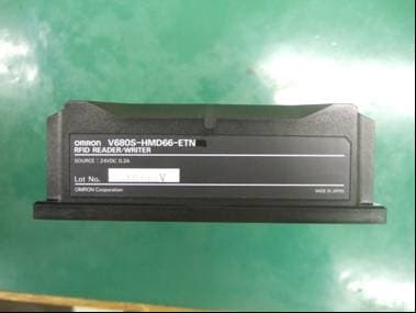
E4EV680S66
Apr 04, 2013Radio Frequency Identification System (RFID System)
Equipment Class
DXX - Part 15 Low Power Communication Device Transmitter