E4EV640HAM11V2Carrier ID Reader/Writer (RFID)
Omron Corporation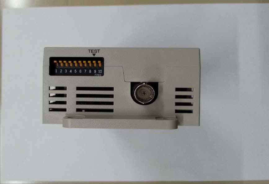
Click to zoom
Application Details
- Equipment Class
- DXX - Part 15 Low Power Communication Device Transmitter
- Date of Grant
- Apr 13, 2015
- Application Purpose
- Original Equipment
- Date of Application
- Apr 13, 2015
- Equipment Note
- Carrier ID Reader/Writer (RFID)
- Frequency Range
- 0.13420000 - 0.13420000
- Company
- Omron Corporation
- Country
- Japan
Documents & Files
Document Text
Text extracted from the exhibit documents filed with the FCC. Open a document above to read the original.
Users Manual
Ethernet port (2) A Port dedicated to connection of a host through a lan cable. CIDRW head connection port (8) A port dedicated to connection of a CIDRW head. Status indicators (3 -6) Four indicator lamps (RUN, COMM, NORM, ERROR) indicate the current operating status of the amplifier unit. 24VDC power terminals (1) Recommended cable : AWG20 - 24 Recommeded connector : Model 1-178288-3 (Tyco Electronics Co.) Recommended compression ring : Model 175217-3 (Tyco Electronics Co.)(These connector and compression ring are supplied with model V640-A90.) Recommended 24 V power supply : Model S8VS-01524(OMRON) Use the product below as a crimping tool for crimping the compression ring. Model 919601-1 (Tyco Electronics Co.) Setup DIP-SW (8) This switch array allows the operator to assign ID No. to amplifier unit and define various operating conditions.DIP-SW settings: factory-setting is all OFF PRECAUTION FOR SAFE USE Dimensions Names and functions RUN Remains stably lit as long as the link unit is operating normally. COMM Remains lit during the communication with a host or an ID tag.Lights when the communications with an ID tag are successful.Lights when the communications with an host or an ID tag are failed. NORMERROR Be sure to limit the tightening torque for the M4 screws as 1.2 N m . material PC+ABS (Unit: mm) General specifications MOUNTING SCREW HOLES No. Description IP Address 1IP Address 2IP Address 3IP Address 4IP Address 5ReservedReservedReservedTest modeReserved Meaning (Content within a box represents factory-setting) 123456789 10 Please turn off this SW.OFF / ONPlease turn off this SW.Please turn off this SW. Supply voltageProtection ratingInsulationresistanceDielectricShock resistanceVibrationresistanceMounting systemAmbienthumidityAmbienttemperatureCurrent consumption Specification 24 VDC, 10%, 15% 150 mA maxIP20 (IEC 60529)150m/s 2 , 3 times each in 6 directions Secured with four M4 screws.(tightening torque:1.2 N m) 1000V AC (50/60Hz, for 1 min.) leak current consumption 5mA max. (between power supply terminal and frame grounding terminal)20 min. (100V DC for appliance) (between power supply terminal and frame grounding terminal)Operating/ Storage: 35% to 85%(No freezing, No dew condensation)Operating: 0 to 40 Storage: 15 to 65 (No freezing, No dew condensation) 10 to 150Hz, 0.20mm double amplitude, acceleration 15m/s 2 , with 10 sweeps of 8min each in 3 directions CIDRW head V640-HS61 Environmentalpollution degree Degree 2 Over voltage category Category Characteristic V640-HAM11-ETN-V2 V640-HAM11-L-ETN-V2 400 mA max Applied standards USA / Europe / Japan / Canada V640-HS62 Please turn off this SW. (12) (18.2) (22.5) DIP SWITCH 160175185 55.5 46 56 80 6.8 6.86.8 0.6 4- φ 4.5 dia. (MOUNTING HOLES) OPERATINGINDICATOR (11.5) (32.5) 43 5 (5. 7) 4-M4 175 ± 0.5 46±0.5 (13) (18) (31.95) (15.8) 24VDC power terminals MAC Address Label Ethernet port * When you set the IP Address by DIP-SW, the IP Address will be fixed as “192.168.1.XXX”, and the Subnet Mask will be fixed as “255.255.255.0”.You can set the IP Address and the Subnet Mask as any value by setting DIP-SW1 - DIP-SW5 to OFF. 1.Ensure safety, be absolutely sure to follow the instructions below:(1) Never use the product in an environment where combustible or explosive gas is present. (2) Please separate from a high-pressure equipment and the power equipment to secure the safety of the operation and maintenance. (3) In the installation, please tighten the screw surely. (Recommended 1.2N m) (4) Please do not insert foreign bodies such as water and the wires from the space of the case. (5) Please do not dismantle, repair or modify this product.(6) Please process as industrial waste when you abandon this product.(7) When you work on wiring and put on and take off cables, CIDRW head, please perform it after switching off this product. (8) Provide enough space around this product for ventilation.(9) Please avoid installing this product near the machinery (a heater, a transformer, large-capacity resistance) that has high the calorific value. (10) Please talk to our office by any chance after you cancel use immediately when you felt abnormality to this product, and having switched it off. 1.About installation site Do not install this product in the locations subject to the following conditions.(1)Place where direct sunshine strikes(2)Place with corroded gas, dust, metallic powder, and salinity(3)Place with condensation due to rapid temperature fluctuations.(4)Place with condensation due to high humidity.(5)Place where vibration and impact more than being provided by specification are transmitted directly to main body. (6)Place with spray of water, oil, and chemical medicine.(7) The working temperature is within the range stipulated in the specifications. 2.About depository site (1) Please follow the save ambient temperature / humidity, and keep this product. 3.About wiring (1)Use the power supply voltage specified in this cocument.(2) Ensure correct polarity when connecting to the +/- power supply terminals. (3)Do not run high-voltage lines and power lines though the same conduit.(4)To avoid static-induced failure, wear a wrist band or equivalent means to release a static charge before touching a terminal or a signal line within a connector. (5)When you put on and take off a CIDRW head, please do not add excessive power to a connector. (6)Please connect the correct CIDRW head to the amplifier unit. PRECAUTION FOR CORRECT USE 4.About cleaning (1)Use alcohol to clean this product.(2)NEVER use an organic solvent such as thinner, benzene, acetone or kerosene, as it will attack resin components or case coating. 5.Power and Graound Cables (1)Use an appropriate ground. An insufficient ground can affect this product operation or result in damage to this product. 6.About the communication range and time (1)Do the communication test with Transponder in the installation environment because the metal, noise and ambient temperature around CIDRW head dam…
Text truncated - open the document above for the full version.
Users Manual
24VDC power terminals (1) Recommended cable : AWG20 - 24 Recommeded connector : Model 1-178288-3 (Tyco Electronics Co.) Recommended compression ring : Model 175217-3 (Tyco Electronics Co.)(These connector and compression ring are supplied with model V640-A90.) Recommended 24 V power supply : Model S8VS-01524(OMRON) Use the product below as a crimping tool for crimping the compression ring. Model 919601-1 (Tyco Electronics Co.) Cables for RS-485 port Recommended cable : Model MVVS 2CX0.5SQ (Tachii Densen Co.) Recommended compression ring : Molde AI0.5-8WH (Phoenix Contact Co.) The following product is recommended as a compression ring for connecting two cables to one terminal. Model AI-TWIN2 ~0.5-8WH (Phoenix Contact Co.) Use the product below as a crimping tool for crimping the compression ring. Model CRIMPFOX UD6 (Phoenix Contact Co.) How to connect cables Fit a compression ring to the stripped section of each cable.Next, being sure of the connector orientation, insert each cable into a corresponding hole on the connector. Securely fasten each cable using the cable locking screw on the connector.An ordinary screwdriver whose shank is tapered at the tip does not go all the way into the hole. Use a miniature flat-blade screwdriver with a straight shank. Tighten the cable locking screws at an appropriated tightening torque (approx. 0.3 N m). Connect the connector to the amplifier unit together with the cables.Match the orientation of amplifier unit side connector with that of cable side connector, insert the cable side connector all the way, and then tighten the connector lock screws.When removing the connector, fully loosen the two lock screws and draw out it straight by holding the protrusions on connector. If the connector does not easily come loose, draw it out while holding down the link unit proper. Setup DIP-SW (9) This switch array allows the operator to assign ID No. to amplifier unit and define various operating conditions.DIP-SW settings: factory-setting is all OFF Dimensions RUN Remains stably lit as long as the link unit is operating normally. COMM Remains lit during the communication with a host or an ID tag.Lights when the communications with an ID tag are successful.Lights when the communications with an host or an ID tag are failed. NORMERROR Set the RS-485 terminator setting to ON for the amplifier units on both ends of multidrop, and to OFF for other units.If only one amplifier unit is operated, set the terminator setting to ON. 0.6mm 3.5mm Side view The following purpose-built screwdriver is available:OMRON: Model XW4Z-00C From of drip: Front view Be sure to limit the tightening torque for the M4 screws as 1.2 N m. material PC+ABS (Unit: mm) General specifications MOUNTING SCREW HOLES V640-HAM11-V4 Amplifier Unit V640-HAM11-L-V2 160175185 55.5 46 56 80 6.8 6.86.80.6 (4.2) (1) (11.5) (32.5) 43 5 (5. 7) (13) (17.75)(12) (32.5) (30.2) (15.8) (12) (18.2) (22.5) 4- φ 4.5 dia. (MOUNTING HOLES) DIP SWITCH OPERATINGINDICATOR 24VDC power terminals RS-485 port RS-232C port 4-M4 175 ± 0.5 46±0.5 RS-232C port (3) This port is for connection to the host or the CIDRW controller: V700-L22 according to RS-232C interface standard. RS-485 port (2) If two or more Amplifier units are connected to one RS-232C port of a host or a CIDRW controller: model V700-L22, this RS-485 port is connected to a RS-485 port on another amplifier unit. An RS-485 port (if any) on the host can be connected to this port. However the RS-232C port and the RS-485 port are unable to be used at the same time. CIDRW head connection port (8) A port dedicated to connection of a CIDRW head. Status indicators (4 -7) Four indicator lamps (RUN, COMM, NORM, ERROR) indicate the current operating status of the amplifier unit. Names and functions Supply voltageProtection ratingInsulationresistanceDielectricShock resistanceVibrationresistanceMounting systemAmbienthumidityAmbienttemperatureCurrent consumption Specification 24 VDC, 10%, 15% 150 mA maxIP20 (IEC 60529)150m/s 2 , 3 times each in 6 directions Secured with four M4 screws.(tightening torque:1.2 N m) 1000V AC (50/60Hz, for 1 min.) leak current consumption 5mA max.(between power supply terminal and frame grounding terminal)20 min. (100V DC for appliance) (between power supply terminal and frame grounding terminal)Operating/ Storage: 35% to 85%(No freezing, No dew condensation) Operating: 0 to 40 Storage: 15 to 65 (No freezing, No dew condensation) 10 to 150Hz, 0.20mm double amplitude, acceleration 15m/s 2 , with 10 sweeps of 8min each in 3 directions CIDRW head V640-HS61 Environmentalpollution degree Degree 2 Over voltage category Category Characteristic V640-HAM11-V4 V640-HAM11-L-V2 400 mA max Applied standards USA / Europe / Japan / Canada V640-HS62 No. Description Node No.1Node No.2Node No.3Node No.4Node No.5 Baud rate setting 1Baud rate setting 2ReservedTest modeRS-485 terminator Meaning (Content within a box represents factory-setting) 123456789 10 OFF / ONOFF / ONPlease turn off this SW.38400 19200 9600 4800bps [ON,ON][ON,OFF][OFF,OFF][OFF,ON] : [No7,No6] 01 31 No. 1 is LSB, and No. 5 is MSB. When all switches are ON,this amplifierunit selects 1:1 protocol. PRECAUTION FOR SAFE USE 1.Ensure safety, be absolutely sure to follow the instructions below:(1) Never use the product in an environment where combustible or explosive gas is present. (2) Please separate from a high-pressure equipment and the power equipment to secure the safety of the operation and maintenance. (3) In the installation, please tighten the screw surely. (Recommended 1.2N m) (4) Please do not insert foreign bodies such as water and the wires from the space of the case. (5) Please do not dismantle, repair or modify this product.(6) Please process as industrial waste when you abandon this product.(7) When you work on wiring and put on and take off cables, CIDRW head, please perform it after switching off this product. (8) Provide enough space around this product for ventilation.(9) Please avoid inst…
Text truncated - open the document above for the full version.
External Photos
Model:V640 -HAM11-ETN-V2 OUTSIDE VIEW PHOT OMRON Corporation Fig.1 V640-HAM11-ETN-V2 Front View Fig.2 V640-HAM11-ETN-V2 Back Side View Fig.3 V640-HAM11-ETN-V2 Left Side View Fig.4 V640-HAM11-ETN-V2 Right Side View Model:V640 -HAM11-ETN-V2 OUTSIDE VIEW PHOT OMRON Corporation Fig.5 V640-HAM11-ETN-V2 Top View Fig.6 V640-HAM11-ETN-V2 Bottom View
External Photos
Model: V640-HAM11-V4 OUTSIDE VIEW PHOT OMRON Corporation Fig.1 V640 -HAM11-V4 Front View Fig. 2 V640-HAM11-V4 Back Side View Fig.3 V640-HAM11-V4 Left Side View Fig.4 V640-HAM11-V4 Right Side View Model: V640-HAM11-V4 OUTSIDE VIEW PHOT OMRON Corporation Fig.5 V640-HAM11-V4 Top View Fig.6 V640-HAM11-V4 Bottom View
External Photos
Model: V640-HAM11-ETN- V2 Antenna Connection VIEW PHOT OMRON Corporation Antenna connection state V640-HAM11-ETN -V2 & V640-HS61 (Antenna)
External Photos
Model: V640-HAM11-V4 Antenna Connection OMRON Corporation Antenna connection state Fig.1 V640-HAM11-V4 & V640-HS61 (Antenna)
ID Label/Location Info
(5.7) 5 56 4-M4 CJ-150068 CONFIDENTIAL 150331 ABCDEF All Rights Reserved SYM DATE E/C CONTENTS E/C NO. SIGN C MATERIALFINISH SCALE 3RD ANGLE SHEET DRWG NO. DESIGNED FOR F A3 1 2 3 45 6 7 8 ABCDE OMRON Corporation TOLERANCES UNLESS SPECIFIED DESIGNED 形式追加 CHECKED APPROVED 1:1 1/1 V640-HAM11-ETN A2 2135011-1 OUTLINE DRWGCONTROLLER,ID コントロ-ラ,IDガイケイズ IT16 T.YOSHIDA B AT [ UNIT : mm ] 10/08/30 AT Y.OKUNO AT H.TERAMOTO A1 131021 形式追加 CJ-130110 マカベ モトシマ A2 規格ラベルSTANDARD LABEL 43 (32.5) (11.5) ETHERNET CONNECTOR イーサネットコネクタ MAC ADDRES LABELMACアドレスラベル DC電源コネクタDC POWER CONNECTOR )13()18( (15.8) (31.95) DIPスイッチ DIP-SWITCH )12()22.5( (18.2) 4-動作表示灯4-OPERATING INDICATOR 185160 4.5取付穴 4-4.5Dia.MOUNTING HOLES 4- 80 46 175 6.86.86.80.6 55.5 取付穴加工寸法MOUNTING SCREW HOLES 460.5 175 0.5 V640-HAM11-ETN-V2-2V640-HAM11-L-ETN-V2V640-HAM11-ETN-V2V640-HAM11-ETN-2V640-HAM11-L-ETNV640-HAM11-ETN使用形式/APPLICATION
ID Label/Location Info
(5.7) 5 56 4-M4 CJ-150068 CONFIDENTIAL 150331 ABCDEF All Rights Reserved SYM DATE E/C CONTENTS E/C NO. SIGN C MATERIALFINISH SCALE 3RD ANGLE SHEET DRWG NO. DESIGNED FOR F A3 1 2 3 45 6 7 8 ABCDE OMRON Corporation TOLERANCES UNLESS SPECIFIED DESIGNED 形式追加 CHECKED APPROVED 1:1 1/1 V640-HAM11-ETN A2 2135011-1 OUTLINE DRWGCONTROLLER,ID コントロ-ラ,IDガイケイズ IT16 T.YOSHIDA B AT [ UNIT : mm ] 10/08/30 AT Y.OKUNO AT H.TERAMOTO A1 131021 形式追加 CJ-130110 マカベ モトシマ A2 規格ラベルSTANDARD LABEL 43 (32.5) (11.5) ETHERNET CONNECTOR イーサネットコネクタ MAC ADDRES LABELMACアドレスラベル DC電源コネクタDC POWER CONNECTOR )13()18( (15.8) (31.95) DIPスイッチ DIP-SWITCH )12()22.5( (18.2) 4-動作表示灯4-OPERATING INDICATOR 185160 4.5取付穴 4-4.5Dia.MOUNTING HOLES 4- 80 46 175 6.86.86.80.6 55.5 取付穴加工寸法MOUNTING SCREW HOLES 460.5 175 0.5 V640-HAM11-ETN-V2-2V640-HAM11-L-ETN-V2V640-HAM11-ETN-V2V640-HAM11-ETN-2V640-HAM11-L-ETNV640-HAM11-ETN使用形式/APPLICATION
Internal Photos
Model: V640-HAM11-ETN- V2 INSIDE VIEW PHOT OMRON Corporation PCB configuration PCB(1) Interface Board PCB(2) RF Module mounting Board Model: V640-HAM11-ETN- V2 INSIDE VIEW PHOT OMRON Corporation Example for assembly of PCB(1) & PCB(2) [V640-HAM11-V4 photo displayed] inside the Case PCB(1) Interface Board PCB(2) RF Module mounting Board Model: V640-HAM11-ETN- V2 INSIDE VIEW PHOT OMRON Corporation PCB(1) Side A PCB(1) Side B PCB(2) Side A PCB(2) Side B Model: V640-HAM11-ETN- V2 INSIDE VIEW PHOT OMRON Corporation PCB(2) Side A without shield
Internal Photos
Model: V640-HAM11-V4 INSIDE VIEW PHOT OMRON Corporation PCB configuration PCB(1) Interface Board PCB(2) RF Module mounting Board Model: V640-HAM11-V4 INSIDE VIEW PHOT OMRON Corporation Example for assembly of PCB(1) & PCB(2) inside the Case PCB(1) Side A PCB(1) Side B PCB(1) Interface Board PCB(2) RF Module mounting Board Model: V640-HAM11-V4 INSIDE VIEW PHOT OMRON Corporation PCB(2) Side A PCB(2) Side B Model: V640-HAM11-V4 INSIDE VIEW PHOT OMRON Corporation PCB(2) Side A without a shield plate
Internal Photos
V640-HS61 [CIDRW (Carrier ID Reader/Writer) Head (antenna)] INSIDE VIEW PHOTO (1/2) OMRON Corporation Overall View Opening the case Inside View Case inside View V640-HS61 [CIDRW (Carrier ID Reader/Writer) Head (antenna)] INSIDE VIEW PHOTO (2/2) OMRON Corporation PCB Side A PCB Side B
Test Report
Test report No. : 10697030H-A-R1 Page : 2 of 22 Issued date : March 25, 2015 Revised date : April 10, 2015 FCC ID : E4EV640HAM11V2 UL Japan, Inc. Ise EMC Lab. 4383-326 Asama-cho, Ise-shi, Mie-ken 516-0021 JAPAN Telephone : +81 596 24 8999 Facsimile : +81 596 24 8124 REVISION HISTORY Original Test Report No.: 10697030H-A Revision Test report No. Date Page revised Contents - (Original) 10697030H-A March 25, 2015- - 1 10697030H-A-R1 April 10, 2015 P. 5 Correction: Detector of the worst margin for Electric Field Strength of Fundamental Emission in clause 3.2 1 10697030H-A-R1 April 10, 2015 P. 9 Correction of name of antenna in Clause 4.2 1 10697030H-A-R1 April 10, 2015 P. 15 Correction of data for Radiated Emission below 30MHz (Fundamental and Spurious Emission) in APPENDIX 1 Test report No. : 10697030H-A-R1 Page : 3 of 22 Issued date : March 25, 2015 Revised date : April 10, 2015 FCC ID : E4EV640HAM11V2 UL Japan, Inc. Ise EMC Lab. 4383-326 Asama-cho, Ise-shi, Mie-ken 516-0021 JAPAN Telephone : +81 596 24 8999 Facsimile : +81 596 24 8124 CONTENTS PAGE SECTION 1: Customer information ..................................................................................................... 4 SECTION 2: Equipment under test (E.U.T.) ........................................................................................ 4 SECTION 3: Test specification, procedures & results ........................................................................ 5 SECTION 4: Operation of E.U.T. during testing ................................................................................. 8 SECTION 5: Conducted Emission ....................................................................................................... 10 SECTION 6: Radiated emission (Fundamental and Spurious Emission) ........................................ 11 SECTION 7: -26dB Bandwidth ............................................................................................................ 13 SECTION 8: 99% Occupied Bandwidth ............................................................................................. 13 APPENDIX 1: Data of EMI test ........................................................................................................... 14 Conducted Emission .......................................................................................................................... 14 Radiated Emission below 30MHz (Fundamental and Spurious Emission) ................................. 15 Radiated Emission above 30MHz (Spurious Emission) ................................................................. 16 -26dB Bandwidth and 99% Occupied Bandwidth ......................................................................... 17 APPENDIX 2: Test instruments .......................................................................................................... 18 APPENDIX 3: Photographs of test setup ............................................................................................ 19 Conducted Emission .......................................................................................................................... 19 Radiated Emission ............................................................................................................................. 20 Worst Case Position .......................................................................................................................... 21 Test report No. : 10697030H-A-R1 Page : 4 of 22 Issued date : March 25, 2015 Revised date : April 10, 2015 FCC ID : E4EV640HAM11V2 UL Japan, Inc. Ise EMC Lab. 4383-326 Asama-cho, Ise-shi, Mie-ken 516-0021 JAPAN Telephone : +81 596 24 8999 Facsimile : +81 596 24 8124 SECTION 1: Customer information Company Name : OMRON Corporation Address : 2-2-1, NISHI-KUSATSU, KUSATSU-CITY, SHIGA-PREF., 525-0035 JAPAN Telephone Number : +81-77-565-5287 Facsimile Number : +81-77-565-5569 Contact Person : Hiroaki Motoshima SECTION 2: Equipment under test (E.U.T.) 2.1 Identification of E.U.T. Type of Equipment : Carrier ID Reader/Writer (RFID) Model No. : V640-HAM11-ETN-V2 (Amplifier Unit) Serial No. : Refer to Section 4, Clause 4.2 Rating : DC 24V Receipt Date of Sample : February 24, 2015 Country of Mass-production : Japan Condition of EUT : Production prototype (Not for Sale: This sample is equivalent to mass-produced items.) Modification of EUT : No Modification by the test lab 2.2 Product Description General Specification Clock frequency(ies) in the system : 8MHz (for both types), 125MHz (EtherNet Communication type only) Radio Specification Radio Type : Transceiver Frequency of Operation : 134.2 kHz Modulation : Amplitude Shift Keying Power Supply (radio part input) : DC 5V Antenna type : Loop Coil Antenna Similar model This EUT has similar model: V640-HAM11-V4. - V640-HAM11-ETN-V2: EtherNet Communication type and Normal distance type - V640-HAM11-V4: Serial Communication type and Normal distance type There is no difference except for these. Test report No. : 10697030H-A-R1 Page : 5 of 22 Issued date : March 25, 2015 Revised date : April 10, 2015 FCC ID : E4EV640HAM11V2 UL Japan, Inc. Ise EMC Lab. 4383-326 Asama-cho, Ise-shi, Mie-ken 516-0021 JAPAN Telephone : +81 596 24 8999 Facsimile : +81 596 24 8124 SECTION 3: Test specification, procedures & results 3.1 Test Specification Test Specification : FCC Part 15 Subpart C: 2015, final revised on January 21, 2015 Title : FCC 47CFR Part15 Radio Frequency Device Subpart C Intentional Radiators Section 15.207 Conducted Emission Section 15.209 Radiated emission limits, general requirements * The EUT complies with FCC Part 15 Subpart B: 2014, final revised on December 23, 2014. FCC Part 15.31 (e) This EUT provides stable voltage (DC 5V) constantly to RF Module regardless of input voltage. Therefore, this EUT complies with the requirement. FCC Part 15.203 Antenna requirement The EUT has an external antenna connector, but it is installed by the professionals. Therefore, the equipment c…
Text truncated - open the document above for the full version.
Test Setup Photos
Test report No. : 10697030H-A-R1 Page : 19 of 22 Issued date : March 25, 2015 Revised date : April 10, 2015 FCC ID : E4EV640HAM11V2 UL Japan, Inc. Ise EMC Lab. 4383-326 Asama-cho, Ise-shi, Mie-ken 516-0021 JAPAN Telephone : +81 596 24 8999 Facsimile : +81 596 24 8124 APPENDIX 3: Photographs of test setup Conducted Emission Photo 1 Photo 2 Test report No. : 10697030H-A-R1 Page : 20 of 22 Issued date : March 25, 2015 Revised date : April 10, 2015 FCC ID : E4EV640HAM11V2 UL Japan, Inc. Ise EMC Lab. 4383-326 Asama-cho, Ise-shi, Mie-ken 516-0021 JAPAN Telephone : +81 596 24 8999 Facsimile : +81 596 24 8124 Radiated Emission Photo 1 Photo 2 Test report No. : 10697030H-A-R1 Page : 21 of 22 Issued date : March 25, 2015 Revised date : April 10, 2015 FCC ID : E4EV640HAM11V2 UL Japan, Inc. Ise EMC Lab. 4383-326 Asama-cho, Ise-shi, Mie-ken 516-0021 JAPAN Telephone : +81 596 24 8999 Facsimile : +81 596 24 8124 Worst Case Position Antenna [Below 30MHz] X-axis [Above 30MHz] Horizontal: Z-axis/ Vertical: Z-axis Amplifier Unit [Below 30MHz] X-axis [Above 30MHz] Horizontal: X-axis/ Vertical: X-axis X-axis X-axis Y-axis Y-axis Z-axis Z-axis Test report No. : 10697030H-A-R1 Page : 22 of 22 Issued date : March 25, 2015 Revised date : April 10, 2015 FCC ID : E4EV640HAM11V2 UL Japan, Inc. Ise EMC Lab. 4383-326 Asama-cho, Ise-shi, Mie-ken 516-0021 JAPAN Telephone : +81 596 24 8999 Facsimile : +81 596 24 8124 Worst Case Position Without Tag With Tag(Worst) End of Report
Contact Information
Applicant
Koji Shimada
Technical Contact
UL Japan, Inc.Takayuki Shimada
[email protected]81-596-24-8999
4383-326 Asama-cho, Ise-shi · Mie-ken · Japan
Test Firm
UL Japan, Inc. Head office EMC Lab.Tetsuya Hashimoto
Technical Specifications
| # | Rule Parts | Frequency Range | Power Output |
|---|---|---|---|
| 1 | 15C | 0.1342 MHz - 0.1342 MHz | - |
Other Applications from Omron Corporation
E4EV640HAM13
Apr 22, 2026RFID Amplifier Unit
Equipment Class
DCD - Part 15 Low Power Transmitter Below 1705 kHz
E4EV640HAM11LV2
Apr 13, 2015Carrier ID Reader/Writer (RFID)
Equipment Class
DXX - Part 15 Low Power Communication Device Transmitter
E4EV680S63
Nov 13, 2014Radio Frequency Identification System (RFID System)
Equipment Class
DXX - Part 15 Low Power Communication Device Transmitter
E4EV680S66
Apr 04, 2013Radio Frequency Identification System (RFID System)
Equipment Class
DXX - Part 15 Low Power Communication Device Transmitter
E4EV680S64
Apr 04, 2013Radio Frequency Identification System (RFID System)
Equipment Class
DXX - Part 15 Low Power Communication Device Transmitter