E4E6CYCIDV6700101Radio Frequency Identification System
Omron Corporation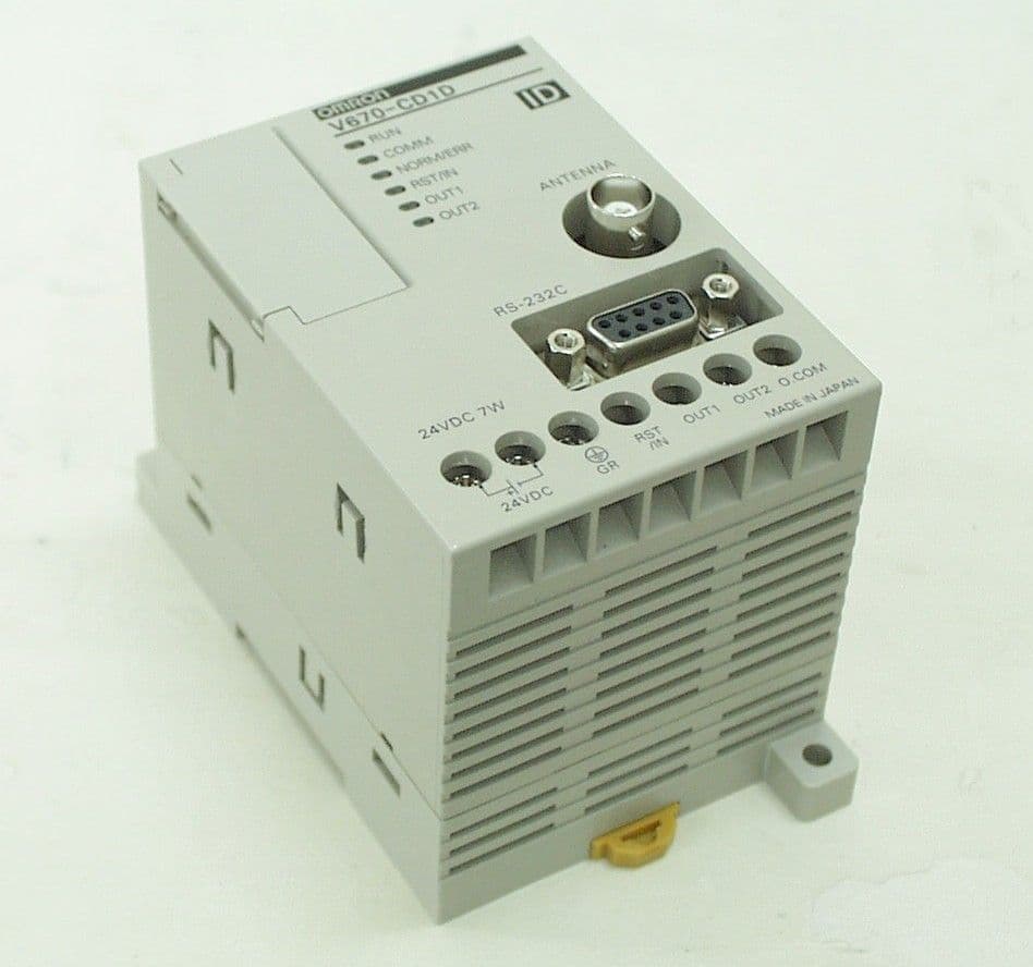
Click to zoom
Application Details
- Equipment Class
- DXX - Part 15 Low Power Communication Device Transmitter
- Date of Grant
- Jun 07, 2001
- Application Purpose
- Original Equipment
- Date of Application
- Jun 07, 2001
- Equipment Note
- Radio Frequency Identification System
- Frequency Range
- 13.56000000 - 13.56000000
- Company
- Omron Corporation
- Country
- Japan
Documents & Files




Document Text
Text extracted from the exhibit documents filed with the FCC. Open a document above to read the original.
Users Manual
xi PRECAUTIONS This section provides general precautions for using the V670-series Electromag netic Inductive RFID System and related devices. The information conta ined in this section is important for the safe and reliable appli cation of the V670-series Electromagnetic Inductive RFID System. You must read this section and understand the information contained before attempting to set up or operate a V670-series Electromagnetic Inductive RFID System. 1 Intended Audience ................................................................................................................ xii 2 General Precautions .............................................................................................................. xii 3 Safety Precautions................................................................................................................. xii 4 Application Precautions ........................................................................................................ xiii 5 Correct Use ........................................................................................................................... xiii 6 Applicable Standards ............................................................................................................ xiii 7 EN/IEC Standards ................................................................................................................. xiv 8 FCC Notices.......................................................................................................................... xiv Safety Precautions 3 xii 1 Intended Audience This manual is intended for the following personnel, who must also have knowledge of electrical systems (an electrical engineer or the equivalent). • Personnel in charge of installing systems. • Personnel in charge of designing systems. • Personnel in charge of managing systems and facilities. 2 General Precautions The user must operate the product according to the performance specifications described in the operation manuals. Before using the product under conditions which are not described in the manual or applying the product to nuclear control systems, railroad systems, aviation systems, vehicles, combustion systems, medical equipment, amusement machines, safety equipment, and other systems, machines, and equipment that may have a serious influence on lives and property if used improperly, consult your OMRON representative. Make sure that the ratings and performance characteristics of the product are sufficient for the systems, machines, and equipment, and be sure to provide the systems, machines, and equipment with double safety mechanisms. This manual provides information for installing and operating the V670-series Electromagnetic Inductive RFID System. Be sure to read this manual before attempting to use the System and keep this manual close at hand for reference during operation. WARNING It is extremely important that a V670-series Electromagnetic Inductive RFID System be used for the specified purpose and under the specified conditions, especially in applications that can directly or indirectly affect human life. You must consult with your OMRON representative before applying the System to the above-mentioned applications. 3 Safety Precautions WARNING Always connect to a ground of 100 Ω or less when installing the System. Not connecting to a ground of 100 Ω or less may result in electric shock. WARNING Do not touch any of the terminals or terminal blocks while the power is being supplied. Doing so may result in electric shock. WARNING Do not attempt to take any unit apart or touch the inside while the power is being supplied. Doing so may result in electric shock. ! ! ! ! Applicable Standards 6 xiii 4 Application Precautions Caution Be sure to observe the following precautions to ensure safety in installing or operating the System. • Do not use the System in an environment subject to flammable, explosive, or corrosive gases. • Do not attempt to take any Units apart, to repair any Units, or to modify any Units in any way. • Be sure that all the mounting screws, terminal screws, and cable connector screws are tightened to the torque specified in the relevant manuals. • Use crimp terminals of specified size for wiring. • Be sure that the items with locking devices are properly locked into place before using the System. • Be sure that the DC Power Supply Unit exc lusively designed for the V670 Series is used and is not connected to any other device. • Be sure that the power supply voltage is within the rated range of 24 VDC+10% and -10%. • Install the ferrite core supplied with the V670-CD1D acc ordi ng to the specified instructions. • Be sure to observe all warnings, cautions, and safety precautions specified in the manual. 5 Correct Use Caution Do not install the V670-CD1D and V670-H11 in the following locations: • Locations subject to direct sunlight. • Locations subject to condensation as the result of severe changes in temperature. • Locations subject to corr osive or flammable gases. • Locations subject to shock or vibration. Caution • Do not wire the lines of the RFID System alongside high–tension or power lines. • Check the polarity of each terminal and make sure not to make mistakes in polarity. Caution Be sure to observe the following precaution when cleaning the V670-CD1D: • Organic solvents may damage the paint coating on t he casing or resin part of the product. Do not use paint thinner or any other organic solvent to clean the product. 6 Applicable Standards The V670-CD1D and V670-H11 conforms to the following standards: ! ! ! ! FCC Notices 8 xiv 7 EN/IEC Standards • In connection with EC unification, eighteen European countries will integrate their conventional safety standards into EN standards. When the EN standards come into effect, they will apply as the unified European standards in place of the conventional safety standards. • EN standards are based on IEC standards. Therefore, machines…
Text truncated - open the document above for the full version.
Users Manual
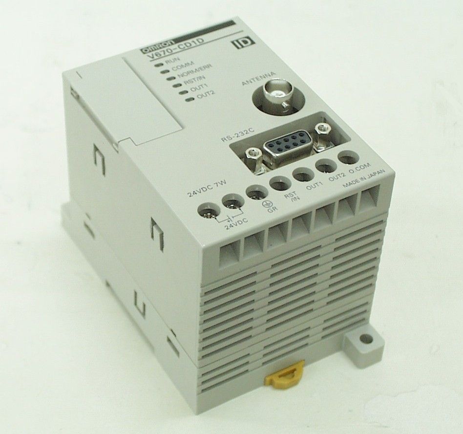
Electromagnetic Coupling Type RF-ID System V670 Series User’s Manual ID Controller, Antenna, and ID Tag ID Controller Model V670-CD1D Antenna Model V670-H11 ID Tag Model V670-D13F03 Catalog No. SCLB-702 Introduction Thank you very much for choosing the electromagnetic coupling type RF-ID system V670 Series. The V670 Series has been developed by OMRON, based on the advanced technology and extensive experience. This user’s manual describes the functions, performance and usage of V670 Series. When you use the V670 Series, follow the instructions below: • Read this user’s manual with care, understand the V670 Series fully and use it appropriately. • Keep this user’s manual handy. When you use the V670 Series in the following environments, we would like you to operate it within the rating and functions, take safety measures such as fail-safe system and consult our person in charge. (1)Use in an unsuitable condition or environment which is not described in the user’s manual (2)Use for nuclear energy control, railroad, aeronautical system, car, combustion equipment, medical equipment, amusement facility, safety device, etc. (3)Use for application which may have a great influence on people’s lives and property and must be executed safely in particu- lar. Notes on use For the safety, be sure to follow the instructions below: 1. Do not operate this device in any flammable, explosive or corrosive gas environment. 2. Do not disassemble, repair nor remodel this device. 3. Tighten the base lock screws and terminal block screws completely. 4. Be sure to use wiring crimp terminal of a specified size. 5. If any cable has a locking mechanism, be sure to check that it has been locked before using it. 6. The DC power supply must meet the following items: (1) Such DC power supply must be used for the V670 Series only and must not be connected to any other devices nor apparatuses. (2) Voltage of such DC power supply must be within the specified rating (24 VDC+10%-10%). 7. Be sure to follow any other warnings, cautions and notices mentioned in this manual. 1. Do not install Model V670-CD1D in the following areas: • Place exposed to the direct sunlight. • Humid place where moisture condensation may occur. • Place affected by vibration or impact. 2. Preliminary check of installation site. This device uses the frequency band 13.56 MHz to communicate with a tag. This frequency band 13.56 MHz is used also as the ISM band (one of frequencies assigned to medical or industrial heater; an application must be filed for installation). So, such heater may affect the communication with a tag or may damage the tag, if the heater is located near this device. If you must this device near such heater, we would like you to check the influence in advance. To minimize general influence of noise, follow the instructions below: • Ground any metallic material located around this device according to Class D (Class III). • Wire this device keeping away from high voltage and heavy current. 3. Be sure to ground any ground terminal according to Class D (conventional Class III). Otherwise, performance may deteriorate. 4. Cleaning of Model V670-D13F03, Model V670-H11 and Model V670-CD1D. • Do not use any thinner. Resin material and case paint are dissolved by thinner. Notes on safety Notes on usage A manual revision history code is added to the end of catalog number shown at the left lower part of front cover and back cover Manual Revision History Revision Code Date of Revision Reason of Revision / Revised Page --October 2000First Edition Catalog No. SCLB-702! !! ! Revision code Chapter 1 Features and System Configuration 1-1Features ..........................................................................................................................1-1 1-2System Configuration .....................................................................................................1-2 Chapter 2Specifications and Performance 2-1Controller........................................................................................................................2-1 2-1-1Component Names and Functions ..................................................................................................... 2-1 2-1-2General Specifications ....................................................................................................................... 2-3 2-1-3Performance Specifications ............................................................................................................... 2-3 2-1-4Communication Specifications .......................................................................................................... 2-4 2-1-5I/O Specifications .............................................................................................................................. 2-4 2-1-6Example of Wiring............................................................................................................................. 2-5 2-1-7Outside Dimension ............................................................................................................................ 2-6 2-2Antenna...........................................................................................................................2-7 2-2-1Specifications..................................................................................................................................... 2-7 2-2-2Outside Dimension ............................................................................................................................ 2-7 2-3Tag ..................................................................................................................................2-8 2-3-1Specifications..................................................................................................................................... 2-8 2-3-2Outside Dimension ...........................................................................................................…
Text truncated - open the document above for the full version.
Operational Description
Integrating Products and Information RFID System using Electromagnetic Coupling Accumulated FA ID Technology Noise resistance Reliability High-speed communications 128-byte R/W in 4 ms FeRAM Number of reads/writes: 1,000 million times Ideal for Distributed Control and Data Processing of High-speed Production and Transfer Lines 10cm V670 5msV670 5ms The OMRON V670 Provides Extremely High-speed R/W Control with Operation as Easy as an ON/OFF SensorThe V670 ensures extremely high-speed R/W (Read/Write) control that makes it possible to read data 20 times and write data 50 times as quick as OMRON's previous models. And, there is no difference in the communications time between reading and writing. The V670 controls a large quantity of R/W data at extremely high speed as easily as a sensor in ON/OFF operation.• Approximately 5 ms for 12-byte read/write• Approximately 14 ms for 128-byte read/write n 12-byte Read Operation OMRON's previous model: 100 ms n 12-byte Write Operation OMRON's previous model: 250 ms Full Support for Production Data Control of High-speed Moving ObjectsUnlike previous models, the required communications processing time of the V670 is so short that data can be read from and written to tags without stopping the tags. The V670 is thus ideal for high-speed production lines, as well as process and inspection stages, to control moving objects.300 m/minute max. (in 12-byte read/write)150 m/minute max. (in 128-byte read/write) Reduced Maintenance with no Battery or Tag ReplacementThe ID Tags for the V670 use a long-life FeRAM (ferroelectric RAM) to eliminate the need for tag replacement, battery replacement, or other such maintenance. Data can be written to and read from an ID Tag at least 1,000 million times. For example, an ID Tag can be accessed 116 times a second under continuous operation 12 hours a day for a total of 200 days a year for 10 years.Data Communications with High-speed Moving ObjectsThe V670 communicates with tags without any timing sensors or tag detection sensors to achieve high-speed data process control.Antennas can be located in parallel with a space of 10 cm between them with no mutual interference that will result in malfunctions. Self-execution Mode supporting High-speed ProcessingIn the previous system, data is always processed by the host controller, which requires a long time. In self-execution mode, the V670 communicates with tags, discriminates data, and gives instructions, thus greatly reducing the time of R/W data processing. Process and inspection performed on moving production lines. Line processing of moving objects • Process/inspection control of foodstuff • Process/inspection of chemicals • Process/inspection of cosmetics • Process/inspection of compact parts • Production of compact machines • Production/inspection of compact parts • RGV• OHT• Carts• Sorters Line with high-speed (short tact time) process control Flow Control of Moving Objects Component Mounting Control Surfing Sorter Distribution Control * FeRAM =ferroelectric RAM 1,000 million times min. 1,000 million times min. Self-execution System Previous System Not required Self-execution System Previous System Controller Controller Coincidence output Error output Error output Trigger input Antenna Antenna (Synchronous sensor) (Synchronous sensor) Tag High-speed movement Coincidence output Host (e.g., PLC) Data communications Trigger input Tag Tag communications Discrimination and instructions Host communication (command) Host communication (response) Discrimination and instructions Total processing time Tag communications Total processing time l Auto Repeat Function l Repeat Input Trigger l Tag Specification Antenna ID Tag The V670 is in repeated communications with tags coming into the communications range. The V670 does not, however, communicate with the same tag more than once. Whenever the V670 detects an input signal rise, the V670 will check the existence of the corresponding tag repeatedly and communicate with the tag. An error will result if the tag cannot be detected. The V670 can communicate only with either of two specified tags (i.e., the tags with which the V670 previously communicated or a tags other than the previous ones.) To Controller's trigger input signal input The V670 does not communicate with tag 1. ID Tag Antenna Tag 2 Tag 1 Antenna
Operational Description
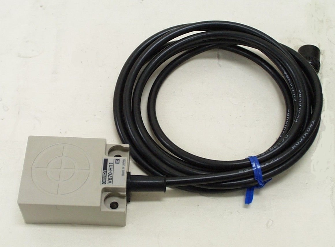
4 RFID System for Electromagnetic Coupling V670 High-speed, Long Life, Batteryless RFID System High-speed communications requiring only 14 ms to read or write 128 bytes of data. Long-life battery–free tags to read and write data 1,000 million times. Versatile functions, such as auto repeat, repeat input trigger, and tag specification. Self-execution mode for data processing with no host controller intervention. Note:The use of the V690 in may be subject to radio regulations and EMC restrictions in individual countries. Contact your OMRON representative for details. Ordering Information ProductModelShape/Specification ID TagV670-D13F0340 40 4.5 mm128 bytes AntennaV670-H1140 53 23 mm2-m cable ControllerV670-CD1D90 66 75 mmRS-232C interface operating at 24 VDC with a single antenna connector Antenna Extension Cables V670-A403 m Material: Polyvinyl chloride Cttt ti ht e ae s o Cab es V670-A4110 m ae aoy y c o de Connectors are not watertight. V670-A4218 m V670-A4328 m Programming ConsoleC200H-PRO27-EOperation monitor, set value display, communications, test communications, and error log functions. Programming Console Conversion Cable V700-P102 mConnects the V670-CD1D and C200H-PRO27. System Configuration ID TagAntennaAntenna Extension Cable Controller (RS-232C Interface) Programming Console Conversion Cable Programming Console V670-D13F03V670-H11 V670-A40 V670-A41 V670-A42 V670-A43 V670-CD1DV700-P10 C200H-PRO27 Note: When extending the antenna cable, do not use any cable other than the Antenna Extension Cables from OMRON. V670 V670 5 Specifications Ratings V670-CD1D Controller ItemSpecifications Host interface specifications RS-232C Number of connectable antennas 1 Power supply voltage 24 VDC±10 % Power consumption 7 W max. Ambient temperature Operating: 0 to 55°C (with no icing) Ambient humidity Operating: 35% to 85% (with no condensation) Ambient temperature Storage: –20 to 75°C (with no icing) Ambient humidity Storage: 35% to 85% (with no condensation) Insulation resistance 20 MΩ min. (at 1,000 VDC) 1. Between the ground and both power supply terminals 2. Between both power supply terminals and both output terminals 3. Between both power supply terminals and casing 4. Between both output terminals and ground 5. Between both output terminals and casing 6. Between the ground terminal and casing Dielectric strength 1,000 VAC for 1 minute in all the above combinations with a maximum leakage current of 5 mA ProtectionPanel-mounting Vibration resistance 10 to 150 Hz, 0.2-mm double amplitude at 15 m/s 2 in X, Y, and Z directions 10 times for 8 minutes each. Shock resistance 150 m/s 2 in X, Y, and Z directions 3 times each (18 times in total) GroundGround at a resistance of less than 100 Ω MaterialPC/ASA resin WeightApprox. 270 g V670-D13F03 ID Tags ItemSpecifications Memory capacity 128 bytes Memory typeFeRAM Memory lifeNumber of accesses: 1,000 million times (See note.) Data storage time 10 years (after the data is written or read) Ambient temperature Operating: –10 to 70°C Ambient temperature Storage: –10 to 70°C Ambient humidity Operating: 35% to 85% Degree of protection IEC60529 IP67 Vibration resistance Destruction: 10 to 2,000 Hz, 1.5-mm double amplitude at 150 m/s 2 in X, Y, and Z directions 10 times for 15 minutes each Shock resistance Destruction: 500 m/s 2 in X, Y, and Z directions 3 times each (18 times in total) MaterialFilled with ABS/Epoxy resin WeightApprox. 6 g Note:The number of accesses is the total number of read or write communications. V670-H11 Antenna ItemSpecification Communications frequency 13.56 MHz Ambient temperature Operating: –10 to 70°C Ambient humidity Operating: 35% to 85% Ambient temperature Storage: –25 to 85°C Ambient humidity 35% to 85% Insulation resistance 20 MΩ min. (at 1,000 VDC) between the terminals and casing Dielectric strength 1,000 VAC for 1 minute between the terminals and casing with a current leakage of 1 mA Degree of protection IEC60529 IP67 Vibration resistance 10 to 150 Hz, 0.7-mm double amplitude at 50 m/s 2 in X, Y, and Z directions 10 times for 8 minutes each Shock resistance150 m/s 2 in X, Y, and Z directions 3 times each (18 times in total) MaterialFilled with ABS/Epoxy resin Cable length2 m WeightApprox. 160 g Note:The connector is not watertight. V670 V670 6 Engineering Data Communications Distance Antenna/ControllerID TagCommunications distanceMeasurement conditions V670-H11+V670-CD1DV670-D13F03 •Communications distance: 5 to 23 mm •Communications range width: 20 mm min. (at a Tag-to-Antenna distance of 20 mm) Non-metal object Antenna Communications distance Tag (See note.) Non-metal object Note:If the background object of the tag is metal, no communications will be possible. For details, refer to the V670 Operation Manual. Communications Range Chart (Typical) Communications Range Characteristics Combination of V670-H11 and V670-D13F03 Communications Time (Reference) Communications time is a period required for communications be- tween the antenna and ID Tag. No. of processing bytes Write (without verification) Read Communications time (ms) OperationNo. of bytesCalculation formula Read 1 to 64 bytesT=0.07 N+4.22 ead 65 to 128 bytesT=0.07 N+5.64 Write1 to 128 bytesT=0.07 N+4.72 N: Number of bytes T: Communications time (ms) Movement Speed (Reference) Ta g movement speed must be a maximum of 50% of the maximum movement speed according to the number of processing bytes to ensure the reliability of communications. Conduct proper on-site tests to determine the tag movement speed. ReadWrite No. of bytes No. of bytes Distance between antenna and tag Movement speed (m/min) Max. movement speed (m/min) V670 V670 7 Dimensions Note:All units are in millimeters unless otherwise indicated. V670-D13F03 ID Tag Two, 3.5 dia. mounting holes Mounting reference level Two, M3 holes Casing material: ABS resin Filler: Epoxy resin Mounting Dimensions V670-H11 Antenna Center of Antenna Two, M4 holes Casing material: ABS resin Filler: Epoxy resin Cable: PVC Mou…
Text truncated - open the document above for the full version.
Test Report
Test report Our reference : 21HE0037-YW-1 Page : 2 of 15 Issued date : April 25, 2001 FCC ID : E4E6CYCIDV6700101 Testing Laboratory A-pex International Co., Ltd. Telephone:+81 596 39 1485 108 Yokowa-cho, Ise-shi Mie-ken 516-1106 JAPANFacsimile:+81 596 39 0232 Table of Contents Page 1 GENERAL INFORMATION3 1.1 Product Description4 1.2 Test Specification4 1.3 Methods & Procedures4 1.4 Test Location4 2 SYSTEM TEST CONFIGURATION5 2. 1 Operation Environment 5 2.2 Justification5 2. 3 Test Procedure5 Figure 2.1 Configuration of Tested System6 3 RADIATED MEASUREMENT PHOTOS8 Figure 3.1 Radiated Measurement Photos8 3.1 Measurement Uncertainty9 4 SUMMARY OF TEST RESULTS10 4.1 Test results10 4.2 Electric Field Strength Measurement of Fundamental Frequency10 4.3 Electric Field Strength of Spurious Emission11 4.4 Frequency Tolerance12 5 RADIATED EMISSION13 5.1 Operating environment13 5.2 Test configuration13 5.3 Test conditions13 5.4 Test procedure13 5.5 Results13 6TEST EQUIPMENT USED14 APPENDIX15 A:Test Data A1 – A3 Test report Our reference : 21HE0037-YW-1 Page : 3 of 15 Issued date : April 25, 2001 FCC ID : E4E6CYCIDV6700101 Testing Laboratory A-pex International Co., Ltd. Telephone:+81 596 39 1485 108 Yokowa-cho, Ise-shi Mie-ken 516-1106 JAPANFacsimile:+81 596 39 0232 1 GENERAL INFORMATION APPLICANT: OMRON CORPORATION TRADE NAME: OMRON ADDRESS: 20 Shimokaiinji, Nagaokakyou-shi, Kyoto 617-8510 Japan Tel: +81-75-957-9849 Fax: +81-75-951-5124 REGULATION(S): FCC Part 15 Subpart C §15.225 MODEL NUMBER: V670-CD1D (ID Controller) V670-H11 (Antenna) FCC ID: E4E6CYCIDV6700101 SERIAL NUMBER: Sample No.8 KIND OF EQUIPMENT: Radio Frequency Identification System TESTED DATE: April 16, 17 and 18, 2001 RECEIPT DATE OF SAMPLE : April 16, 2001 REPORT FILE NUMBER: 21HE0037YW-1 TEST SITE: A-PEX Yokowa No.1 and No.2 Open Test Site Test report Our reference : 21HE0037-YW-1 Page : 4 of 15 Issued date : April 25, 2001 FCC ID : E4E6CYCIDV6700101 Testing Laboratory A-pex International Co., Ltd. Telephone:+81 596 39 1485 108 Yokowa-cho, Ise-shi Mie-ken 516-1106 JAPANFacsimile:+81 596 39 0232 1.1 Product Description Model: V670-CD1F(ID Controller) and V670-H11(Antenna) (referred to as the EUT in this report) is a Radio Frequency Identification System. The specification is as following: Carrier Frequency: 13.56MHz. Operation Voltage: DC24V Modulation: Amplitude Shift Keying 1.2 Test Specification Test Specification : FCC Part 15 Subpart C Title: FCC 47CFR Part15 Radio Frequency Device Subpart C Intentional Radiators §15.225 Operation within the Band 13.553 – 13.567MHz 1.3 Methods & Procedures No.ItemTest ProcedureSpecificationRemarks 1 Electric Field Strength of Fundamental Emission FCC/ANSI C63.4:1992§15.225(a) - 2 Electric Field Strength of Spurious Emission FCC/ANSI C63.4:1992§15.225(b) - 3Frequency ToleranceFCC/ANSI C63.4:1992§15.225(c)- 1.4 Test Location A-PEX International Co.,Ltd. Yokowa No.1 and No.2 test site 108 Yokowa-cho, Ise-shi, Mie-ken 516-1106 Japan Telephone number: +81-596-39-1485 Facsimile number: +81-596-39-0232 This site has been fully described in a report submitted to FCC office, and listed on September 16, 2000(Registration number: 90412/No.1) and October 26, 2000(Registration number: 90411/No.2). Test report Our reference : 21HE0037-YW-1 Page : 5 of 15 Issued date : April 25, 2001 FCC ID : E4E6CYCIDV6700101 Testing Laboratory A-pex International Co., Ltd. Telephone:+81 596 39 1485 108 Yokowa-cho, Ise-shi Mie-ken 516-1106 JAPANFacsimile:+81 596 39 0232 2 SYSTEM TEST CONFIGURATION 2.1 Operation Modes The EUT exercise program used during radiated testing was designed to exercise the various system components in a manner similar to typical use. The sequence is used: Operation Mode : Transmitting 2.2 Justification : The system was configured in typical fashion (as a customer would normally use it) for testing. 2.3 Test Procedure Tabletop Equipment Radiated Emissions EUT was placed on a platform of nominal size, 1.5m by 1m, raised 80cm above the conducting ground plane. Test was made with the antenna positioned in both the horizontal and vertical planes of polarization. The measurement antenna was varied in height above the conducting ground plane to obtain the maximum signal strength. (above 30MHz) The measurement distance was 3m. Test report Our reference : 21HE0037-YW-1 Page : 6 of 15 Issued date : April 25, 2001 FCC ID : E4E6CYCIDV6700101 Testing Laboratory A-pex International Co., Ltd. Telephone:+81 596 39 1485 108 Yokowa-cho, Ise-shi Mie-ken 516-1106 JAPANFacsimile:+81 596 39 0232 Figure2.1 Configuration of Tested System Front View D B:EUT A:EUT C AC120V/60Hz * Test data was taken under worse case conditions. Top View B:EUT A:EUT C D AC120V/60Hz *Test data was taken under worse case conditions. Test report Our reference : 21HE0037-YW-1 Page : 7 of 15 Issued date : April 25, 2001 FCC ID : E4E6CYCIDV6700101 Testing Laboratory A-pex International Co., Ltd. Telephone:+81 596 39 1485 108 Yokowa-cho, Ise-shi Mie-ken 516-1106 JAPANFacsimile:+81 596 39 0232 Description of EUT and Support equipment No.ItemModel numberSerial numberManufacturerRemark AAntennaV670-H11-OMRON CorporationEUT BID ControllerV670-CD1D0931OMRON CorporationEUT CDC Power SupplyS82K-0302423690OMRON Corporation- DID TagV670-D13F03-OMRON Corporation- List of cables used No.NameLength (m)ShieldRemark DC Power Cable0.35N- AC Power Cable1.5N- Antenna Cable1.9Y- RS232C Cable2.4Y- Test report Our reference : 21HE0037-YW-1 Page : 8 of 15 Issued date : April 25, 2001 FCC ID : E4E6CYCIDV6700101 Testing Laboratory A-pex International Co., Ltd. Telephone:+81 596 39 1485 108 Yokowa-cho, Ise-shi Mie-ken 516-1106 JAPANFacsimile:+81 596 39 0232 3 RADIATED MEASUREMENT PHOTOS Figure 3.1 Radiated Measurement Photos Test report Our reference : 21HE0037-YW-1 Page : 9 of 15 Issued date : April 25, 2001 FCC ID : E4E6CYCIDV6700101 Testing Laboratory A-pex International Co., Ltd. Telephone:+81 596 39 1485 108 Yokowa-cho, Ise-shi Mie-ken 516-1106 JAPANFacsimile:+81…
Text truncated - open the document above for the full version.
Test Setup Photos
Test report Our reference : 21HE0037-YW-1 Page : 8 of 15 Issued date : April 25, 2001 FCC ID : E4E6CYCIDV6700101 Testing Laboratory A-pex International Co., Ltd. Telephone:+81 596 39 1485 108 Yokowa-cho, Ise-shi Mie-ken 516-1106 JAPANFacsimile:+81 596 39 0232 3 RADIATED MEASUREMENT PHOTOS Figure 3.1 Radiated Measurement Photos
Contact Information
Applicant
Koji Shimada
Technical Contact
A-pex International Co., Ltd.Naoki Sakamoto
[email protected]+81 596 39 1485
108 Yokowa-cho · Ise-shi, Mie-ken · Japan
Test Firm
UL Japan, Inc.Kazunori Nishimura
Technical Specifications
| # | Rule Parts | Frequency Range | Power Output |
|---|---|---|---|
| 1 | 15C | 13.56 MHz - 13.56 MHz | - |
Other Applications from Omron Corporation
E4EV640HAM13
Apr 22, 2026RFID Amplifier Unit
Equipment Class
DCD - Part 15 Low Power Transmitter Below 1705 kHz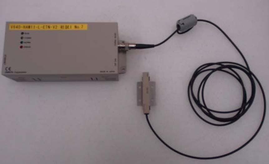
E4EV640HAM11LV2
Apr 13, 2015Carrier ID Reader/Writer (RFID)
Equipment Class
DXX - Part 15 Low Power Communication Device Transmitter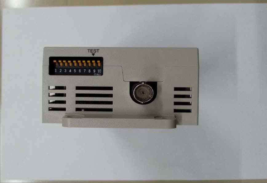
E4EV640HAM11V2
Apr 13, 2015Carrier ID Reader/Writer (RFID)
Equipment Class
DXX - Part 15 Low Power Communication Device Transmitter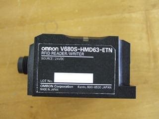
E4EV680S63
Nov 13, 2014Radio Frequency Identification System (RFID System)
Equipment Class
DXX - Part 15 Low Power Communication Device Transmitter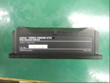
E4EV680S66
Apr 04, 2013Radio Frequency Identification System (RFID System)
Equipment Class
DXX - Part 15 Low Power Communication Device Transmitter