E4E6CYCIDV6700104Modular RFID Transmitter
Omron Corporation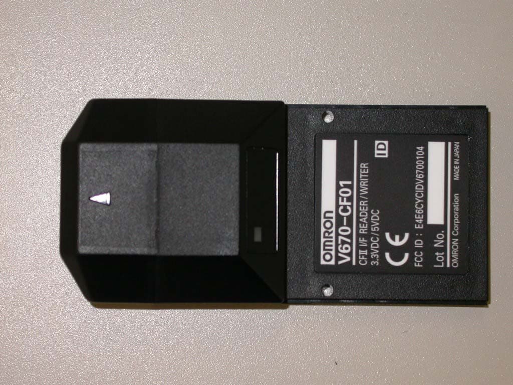
Click to zoom
Application Details
- Equipment Class
- DXX - Part 15 Low Power Communication Device Transmitter
- Date of Grant
- Jul 29, 2004
- Application Purpose
- Original Equipment
- Date of Application
- Jul 29, 2004
- Equipment Note
- Modular RFID Transmitter
- Frequency Range
- 13.56000000 - 13.56000000
- Company
- Omron Corporation
- Country
- Japan
Documents & Files
Document Text
Text extracted from the exhibit documents filed with the FCC. Open a document above to read the original.
Users Manual
Electromagnetic Inductive RFID System V670 Series User's Manual Cat. No. ntlp-E1-01 CF Reader/Writer V670-CF01 ID Tag V670-D13F03 V670-D13F01 V670-D13F01H はじめに 第 1 章 第 2 章 第 3 章 第 4 章 I ntroduction SECTION 1 SECTION 2 SECTION 3 SECTION 4 SECTION 5 SECTION 6 Introduction SECTION 1 SECTION 2 SECTION 3 SECTION 4 SECTION 5 SECTION 6 Standard Conformity Product Outline Communications Preparations Functions Commands Troubleshooting Appendices (Specifications and Dimensions, Characteristics Data Based on Operating Conditions, Memory Map, Maintenance and Inspection, Table of JIS8 Unit Code (ASCII), Degree of Protection) Electromagnetic Inductive RFID System V670-CF01CF Reader/Writer V670-D13F03ID Tag V670-D13F01ID Tag V670-D13F01HID Tag User's Manual 2 Introduction Introduction Electromagnetic Inductive RFID System User's Manual Introduction Introduction OMRON products are manufactured for use according to proper procedures by a qualified operator and only for the purposes described in this manual. Observe the following precautions when using a V670-series Electromagnetic Inductive RFID System. • Read and understand this manual before attempting to use the product and use the product correctly. • Keep this manual in a safe but accessible location so that it can be used as reference when required. Read and Understand this User’s Manual Please read and understand this instruction manual before storing, installing, programming, operating, maintaining, or disposing of the products. Please consult your OMRON representative if you have any questions or comments. Warranty and Limitations of Liability WARRANTY OMRON's exclusive warranty is that the products are free from defects in materials and workmanship for a period of one year (or other period if specified) from date of sale by OMRON. OMRON MAKES NO WARRANTY OR REPRESENTATION, EXPRESS OR IMPLIED, REGARDING NON-INFRINGE- MENT, MERCHANTABILITY, OR FITNESS FOR PARTICULAR PURPOSE OF THE PRODUCTS. ANY BUYER OR USER ACKNOWLEDGES THAT THE BUYER OR USER ALONE HAS DETERMINED THAT THE PRODUCTS WILL SUITABLY MEET THE REQUIREMENTS OF THEIR INTENDED USE. OMRON DISCLAIMS ALL OTHER WARRAN- TIES, EXPRESS OR IMPLIED. LIMITATIONS OF LIABILITY OMRON SHALL NOT BE RESPONSIBLE FOR SPECIAL, INDIRECT, OR CONSEQUENTIAL DAMAGES, LOSS OF PROFITS OR COMMERCIAL LOSS IN ANY WAY CONNECTED WITH THE PRODUCTS, WHETHER SUCH CLAIM IS BASED ON CONTRACT, WARRANTY, NEGLIGENCE, OR STRICT LIABILITY. In no event shall the responsibility of OMRON for any act exceed the individual price of the product on which liability is asserted. IN NO EVENT SHALL OMRON BE RESPONSIBLE FOR WARRANTY, REPAIR, OR OTHER CLAIMS REGARDING THE PRODUCTS UNLESS OMRON'S ANALYSIS CONFIRMS THAT THE PRODUCTS WERE PROPERLY HANDLED, STORED, INSTALLED, AND MAINTAINED AND NOT SUBJECT TO CONTAMINATION, ABUSE, MISUSE, OR INAP- PROPRIATE MODIFICATION OR REPAIR. 3 Electromagnetic Inductive RFID System User's Manual Introduction Introduction Introduction Application Considerations SUITABILITY FOR USE OMRON shall not be responsible for conformity with any standards, codes, or regulations that apply to the combination of products in the customer's application or use of the products. At the customer's request, OMRON will provide applicable third party certification documents identifying ratings and limi- tations of use that apply to the products. This information by itself is not sufficient for a complete determination of the suit- ability of the products in combination with the end product, machine, system, or other application or use. The following are some examples of applications for which particular attention must be given. This is not intended to be an exhaustive list of all possible uses of the products, nor is it intended to imply that the uses listed may be suitable for the products: • Outdoor use, uses involving potential chemical contamination or electrical interference, or conditions or uses not described in this instruction manual. • Nuclear energy control systems, combustion systems, railroad systems, aviation systems, medical equipment, amuse- ment machines, vehicles, safety equipment, and installations subject to separate industry or government regulations. • Systems, machines, and equipment that could present a risk to life or property. Please know and observe all prohibitions of use applicable to the products. NEVER USE THE PRODUCTS FOR AN APPLICATION INVOLVING SERIOUS RISK TO LIFE OR PROPERTY WITH- OUT ENSURING THAT THE SYSTEM AS A WHOLE HAS BEEN DESIGNED TO ADDRESS THE RISKS, AND THAT THE OMRON PRODUCTS ARE PROPERLY RATED AND INSTALLED FOR THE INTENDED USE WITHIN THE OVER- ALL EQUIPMENT OR SYSTEM. PROGRAMMABLE PRODUCTS OMRON shall not be responsible for the user's programming of a programmable product, or any consequence thereof. Disclaimers PERFORMANCE DATA Performance data given in this manual is provided as a guide for the user in determining suitability and does not consti- tute a warranty. It may represent the result of OMRON’s test conditions, and the users must correlate it to actual applica- tion requirements. Actual performance is subject to the OMRON Warranty and Limitations of Liability. CHANGE IN SPECIFICATIONS Product specifications and accessories may be changed at any time based on improvements and other reasons. It is our practice to change model numbers when published ratings or features are changed, or when significant construc- tion changes are made. However, some specifications of the products may be changed without any notice. When in doubt, special model numbers may be assigned to fix or establish key specifications for your application on your request. Please consult with your OMRON representative at any time to confirm actual specifications of purchased products. DIMENSIONS AND WEIGHTS Dimensions and weights are nominal and are not to be used for manufacturing purposes, even when tolerances are shown. ERRORS AND OMISSIONS The information in this instruction manual has been carefully chec…
Text truncated - open the document above for the full version.
Attestation Statements
FCC ID : E4E6CYCIDV6700104 Date: July 2, 2004 Model : V670-CF01 Applicant : OMRON CORPORATION Request for Limited Modular Approval The modular transmitter (Model: V670-CF01) is designed by OMRON CORPORATION. This modular transmitter will be equipped only on Bar code Printer which is produced by OMRON CORPORATION or the manufacturer consigned the production by OMRON CORPORATION. The modular transmitter complies the module basic requirement (Item 1 to 8 ) in FCC Public Notice: Part 15 Unlicensed Modular Transmitter Approval(DA00-1407) as indicated below: [Module basic requirement] (1) Have its own RF shielding.: Although RF module itself is not shielded, the module complies with FCC requirements as standalone. The equipment with which the module is used is limited. (Please refer to the A2 Photo) Figure of EUT A1 Photo (Modular transmitter) A2 Photo Operating mode (2) The modular transmitter must have buffered modulation/data inputs.: Data input to the modular transmitter is controlled as not generating excessive data speed and abnormal modulation. (3) The modular transmitter must have its own power supply regulation.: The modular transmitter does not have its own power supply, but regulated power of 3.3V is supplied from host equipment Pocket PC (PDA). Therefore, the equipment meets this requirement. (4) The modular transmitter must comply with the antenna requirements of Section 15.203 and 15.204(c).: The modular transmitter is installed in the end product by the professionals. Neither antenna nor cable is to be exchanged with any other replacement. Neither does the length of cable change. Please refer to the A1 Photo. (5) The modular transmitter must be tested in a stand alone.: The modular transmitter has been performed the testing as a stand alone and then confirmed the compliance. Please refer to the Test report. (No. 24IE0033-HO) (6) The modular transmitter must be labeled with its own FCC ID number, and, if the FCC ID is not visible when The module is installed inside another device, then the outside of the device into which the module is installed must also display a label referring to the enclosed module.: The modular transmitter is labeled with its own FCC ID. It will be directly sold to the end users and the end users will install it into the host device. Therefore, modular transmitter complies with this requirement. (7) The modular transmitter must comply with any specific rule or operating requirements applicable to the transmitter and the manufacturer must provide adequate instructions along with the module to explain any such requirements.: The necessary explanation to be complied with this requirement is contained in the manual. (8) The modular transmitter must comply with any applicable RF exposure requirements.: Limits for General Population / Uncontrolled Exposure. Limit (E) = 824/13.56MHz = 60.8V/m Measurement result: f 13.56MHz 42.1dBuV/m at 10m EUT is complied with FCC requirements. Please refer to test report. (No.24IE0033-HO) Hiroshi Yamazaki (Dept. Manager) OMRON CORPORATION. Antenna connector PWB Loop Antenna
External Photos
OMRON Corporation E4E6CYCIDV6700104 External Photo Top Bottom OMRON Corporation E4E6CYCIDV6700104 Front Rear OMRON Corporation E4E6CYCIDV6700104 Side A Side B OMRON Corporation E4E6CYCIDV6700104 Passive Tag 1 Passive Tag 2 OMRON Corporation E4E6CYCIDV6700104 Passive Tag 3
Internal Photos
OMRON Corporation E4E6CYCIDV6700104 Internal Photo Case Removed (1) Case Removed (2) OMRON Corporation E4E6CYCIDV6700104 CF – Side A CF – Side B OMRON Corporation E4E6CYCIDV6700104 PWB (1) – Side A PWB (1) – Side B OMRON Corporation E4E6CYCIDV6700104 PWB (2) – Side A PWB (2) – Side B OMRON Corporation E4E6CYCIDV6700104 PWB (3) – Side A PWB (3) – Side B
Test Report
Test report No. : 24IE0033-HO Page : 2 of 20 Issued date : June 21, 2004 FCC ID : E4E6CYCIDV6700104 UL Apex Co., Ltd. Head Office EMC Lab. 4383-326 Asama-cho, Ise-shi, Mie-ken 516-0021 JAPAN Telephone : +81 596 24 8116 Facsimile : +81 596 24 8124 MF060b(10.04.03) CONTENTS PAGE SECTION 1: Client information...................................................................................................... 3 SECTION 2: Equipment under test (E.U.T.) ................................................................................. 3 SECTION 3: Test specification, procedures & results .................................................................. 4 SECTION 4: Operation of E.U.T. during testing .......................................................................... 6 SECTION 5: Radiated emission (Fundamental and Spurious Emission) ................................... 7 SECTION 6: -20dB Bandwidth ....................................................................................................... 8 SECTION 7: Frequency Tolerance .................................................................................................8 APPENDIX 1: Photographs of test setup........................................................................................ 9 Radiated emission (Spurious emission)................................................................................ 9 Worst Case Position (Z-axis: 0deg) .................................................................................... 10 APPENDIX 2: Test instruments .................................................................................................... 11 APPENDIX 3: Data of EMI test .................................................................................................... 12 Radiated emission(Fundamental emission) ....................................................................... 12 Radiated emission (Spurious emission : below 30MHz)................................................... 14 Radiated emission (Spurious emission : above 30MHz)................................................... 15 –20dB Bandwidth .................................................................................................................16 Frequency Tolerance ........................................................................................................... 17 Test report No. : 24IE0033-HO Page : 3 of 20 Issued date : June 21, 2004 FCC ID : E4E6CYCIDV6700104 Revised date : July 23, 2004 UL Apex Co., Ltd. Head Office EMC Lab. 4383-326 Asama-cho, Ise-shi, Mie-ken 516-0021 JAPAN Telephone : +81 596 24 8116 Facsimile : +81 596 24 8124 MF060b(10.04.03) SECTION 1: Client information Company Name : OMRON Corporation Industrial Automation Business Company Brand or Trade name : OMRON Address : Shiokoji-hirokawa, Shimogyo-ku, Kyoto, 600-8530 JAPAN Telephone Number : +81-75-344-7069 Facsimile Number : +81-75-344-7069 Contact Person : Hiroshi Yamazaki SECTION 2: Equipment under test (E.U.T.) 2.1 Identification of E.U.T. Type of Equipment : Radio Frequency Identification System and ID Tag Model No. : V670-CF01 Model No.(ID Tag) : V670-D13F03/V670-D13F01/V670-D13F01H Serial No. : 4 / 0940V(ID Tag) Country of Manufacture : Japan Rating : DC3.3V / 0.2A Receipt Date of Sample : June 07, 2004 Condition of EUT : Production model 2.2 Product Description Model No: V670-CF01 is a ID System. The Antenna in the V670-CF01 exchanges data to and from various types of Radio Frequency (RF) ID Tags. Each Tag is attached on an object that is to be identified by the Antenna. The data exchange between the Tag and the Antenna is bi-directional. Equipment Type : Transceiver Type of modulation : Amplitude Shift Keying Mode of operation : Simplex Antenna Type : PWB Loop Antenna Antenna area : 176.625 mm^ 2 Method of Frequency Generation : 13.56MHz(Crystal) Operating Temperature : 0 deg. C. to +40 deg. C. FCC 15.31 (e) This test was performed with the New Lithium Battery (DC 7.4V/PDA) and the constant voltage(DC 3.3V) was supplied to this EUT during the tests. Therefore, this EUT complies with the requirement. *The PDA used with EUT is selected by the client. The PDA has DC 3.3V output power. EUT has the built-in circuit, which has the stable voltage. FCC Part 15.203 Antenna requirement Type of Equipment and its antenna comply with this requirement since it has an original antenna connector in host device Model No. V670-CF01 when they are put up for sale. It is impossible for end users to replace the antenna because the antenna is mounted inside of the EUT. Therefore, the equipment complies with the antenna requirement of Section 15.203. Test report No. : 24IE0033-HO Page : 4 of 20 Issued date : June 21, 2004 FCC ID : E4E6CYCIDV6700104 Revised date : July 23, 2004 UL Apex Co., Ltd. Head Office EMC Lab. 4383-326 Asama-cho, Ise-shi, Mie-ken 516-0021 JAPAN Telephone : +81 596 24 8116 Facsimile : +81 596 24 8124 MF060b(10.04.03) SECTION 3: Test specification, procedures & results 3.1 Test Specification Test Specification : FCC Part 15 Subpart B : 2003 Section 15.109 FCC Part 15 Subpart C : 2003 Section 15.225 and 15.209 Title : FCC 47CFR Part15 Radio Frequency Device Subpart C Intentional Radiators Section 15.225 : Operation within the band 13.553 – 13.567 MHz 3.2 Procedures and results 1) FCC Part 15 Subpart C : 2003 No. Item Test Procedure Specification Remarks Deviation Worst margin Results 1 Electric Field Strength of Fundamental Emission and Band Edges ANSI C63.4:2003 8. Radiated emission measurements Section 15.225(a)(b)(c) Radiated N/A 61.0dB 13.5610MHz Complied 2 -20dB Bandwidth ANSI C63.4:2003 Annex H. 6 Occupied bandwidth measurements Section15.215(c) Radiated N/A - N/A 3 Electric Field Strength of Spurious Emission ANSI C63.4:2003 8. Radiated emission measurements Section15.225(d) Section15.209 Radiated N/A 5.4dB 718.817MHz Horizontal Complied 4 Frequency Tolerance ANSI C63.4:2003 Annex H. 5 Frequency measurements Section15.225(e) Radiated N/A 87…
Text truncated - open the document above for the full version.
Test Setup Photos
Test report No. : 24IE0033-HO Page : 9 of 20 Issued date : June 21, 2004 FCC ID : E4E6CYCIDV6700104 UL Apex Co., Ltd. Head Office EMC Lab. 4383-326 Asama-cho, Ise-shi, Mie-ken 516-0021 JAPAN Telephone : +81 596 24 8116 Facsimile : +81 596 24 8124 MF060b(10.04.03) APPENDIX 1: Photographs of test setup Radiated emission (Spurious emission) Front Rear Test report No. : 24IE0033-HO Page : 10 of 20 Issued date : June 21, 2004 FCC ID : E4E6CYCIDV6700104 UL Apex Co., Ltd. Head Office EMC Lab. 4383-326 Asama-cho, Ise-shi, Mie-ken 516-0021 JAPAN Telephone : +81 596 24 8116 Facsimile : +81 596 24 8124 MF060b(10.04.03) Worst Case Position (Y-axis: 0deg) X-axis Y-axis Z-axis
Contact Information
Applicant
Koji Shimada
Technical Contact
Non-Technical Contact
UL Apex Co., Ltd.Yukari Ito
[email protected]81-596-24-8116
Test Firm
UL Apex Co., Ltd.Tetsuya Hashimoto
Technical Specifications
| # | Rule Parts | Frequency Range | Power Output |
|---|---|---|---|
| 1 | 15C | 13.56 MHz - 13.56 MHz | - |
Other Applications from Omron Corporation
E4EV640HAM13
Apr 22, 2026RFID Amplifier Unit
Equipment Class
DCD - Part 15 Low Power Transmitter Below 1705 kHz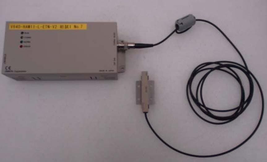
E4EV640HAM11LV2
Apr 13, 2015Carrier ID Reader/Writer (RFID)
Equipment Class
DXX - Part 15 Low Power Communication Device Transmitter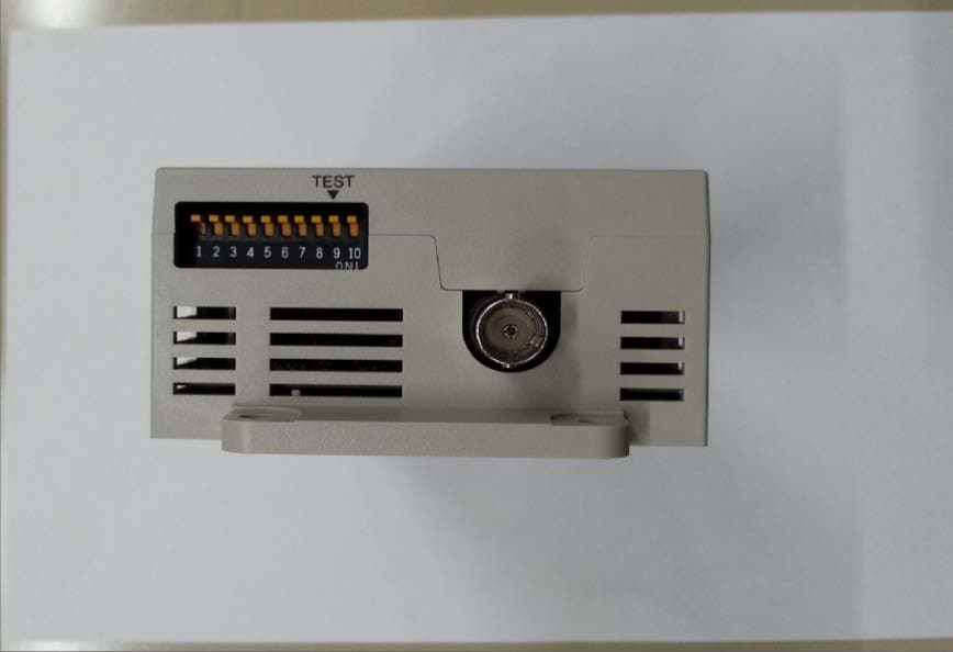
E4EV640HAM11V2
Apr 13, 2015Carrier ID Reader/Writer (RFID)
Equipment Class
DXX - Part 15 Low Power Communication Device Transmitter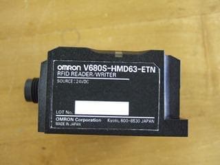
E4EV680S63
Nov 13, 2014Radio Frequency Identification System (RFID System)
Equipment Class
DXX - Part 15 Low Power Communication Device Transmitter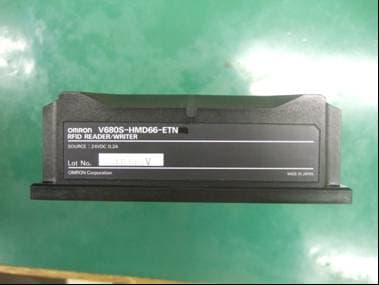
E4EV680S66
Apr 04, 2013Radio Frequency Identification System (RFID System)
Equipment Class
DXX - Part 15 Low Power Communication Device Transmitter