E4E6CYCIDV6900101Read / Write Antenna
Omron Corporation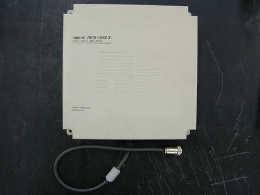
Click to zoom
Application Details
- Equipment Class
- FDS - Part 15 Field Disturbance Sensor
- Date of Grant
- Feb 13, 2002
- Application Purpose
- Original Equipment
- Date of Application
- Feb 11, 2002
- Equipment Note
- Read / Write Antenna
- Frequency Range
- 2437.50000000 - 2460.00000000
- Company
- Omron Corporation
- Country
- Japan
Documents & Files
Document Text
Text extracted from the exhibit documents filed with the FCC. Open a document above to read the original.
Users Manual
Microwave Type RFID System V690 Series User’s Manual Read/Write Antenna, ID Tag, and Link Unit Read/Write Antenna Model V690-HMG01 ID Tag Model V690-D8KR01 Link Unit Model V690-L01 Catalog No. Z149-E1-01 Introduction Thank you very much for choosing the microwave type RFID system V690 Series. The V690 Series has been developed by OMRON, based on the advanced technology and extensive experience. This user’s manual describes the functions, performance and usage of V690 Series. When you use the V690 Series, follow the instructions below: • V690 series must be operated by a qualified electrical engineer who experts on knowledge about electricity. • Read this user’s manual with care, understand the V690 Series fully and use it appropriately. • Keep this user’s manual handy. When you use the V690 Series in the following environments, we would like you to operate it within the rating and functions, take safety measures such as fail-safe system and consult our person in charge. (1)Use in an unsuitable condition or environment which is not described in the user’s manual (2)Use for nuclear energy control, railroad, aeronautical system, car, combustion equipment, medical equipment, amusement facility, safety device, etc. (3)Use for application which may have a great influence on people’s lives and property and must be executed safely in particu- lar. Notes on use • •• • Warning symbols and meanings For safety operation of V690 Series RFID system, the warning symbols below are used in this User’s Manual. The notes mentioned below gives you an important message for safety operation. Be sure to follow the instruction. The warning symbols and meaning are as follows: • •• • Description of symbol Notes on safety WARNING The hazard or unsafe practice could result in severe injury or death. • •• • Explosive! It may burst under a particular condition. WARNING Lithium battery is contained in an ID tag. Do not disassemble, heat above 212 °F (100°C) or incin- erate the ID tag. Otherwise fire, explosion and/or burns may result.. . For the safety, be sure to follow the instructions below: 1. Do not operate this device in any flammable, explosive or corrosive gas environment. 2. Do not disassemble, repair nor remodel this device. 3. Tighten the base lock screws and terminal block screws completely. 4. Be sure to use wiring crimp terminal of a specified size. 5. The 24 VDC power supply must meet the following items: (1) Such 24 VDC power supply must be used for the V690 Series only and must not be connected to any other devices nor appara- tuses. (2) Voltage of such DC power supply must be within the specified rating (24 VDC +10%-15%). 6. Be sure to follow any other Warnings, Cautions and Correct Usage mentioned in this manual. . 1. Do not install model V690-HMG01, model V690-D8KR01 and model V690-L01 in the following areas: • Place exposed to the direct sunlight. • Humid place where moisture condensation may occur. • Place affected by vibration or impact. 2. Preliminary check of installation site. This device uses the frequency band 2450 MHz for the communication between an antenna and tag. Some of radio equipment, such as wireless LAN, cellular phone, personal handyphone system and transceiver, motor and switching power supply may generate a radio wave (noise) which affects the communication with a tag. If you must use this device near such heater, we would like to ask you to check the influence in advance. To minimize general influence of noise, follow the instructions below: • Ground any metallic material located around this device according to Class D (Class III). • Wire this device keeping away from high voltage and heavy current. 3. Ambient environment and communication range • The communication range varies depending on the installation site environment. This is because a metal material and the ground reflect a radio wave, and water and human body absorb it. Locate an antenna and tag in the communication range and check the radio wave environment in advance. • The Read/Write antenna model V690-HMG01 has a communication test command to check the radio wave environment at a working site. (Refer to Section 3-5.) 4. Be sure to ground any ground terminal according to Class D (conventional Class III). Otherwise, performance may deteriorate. 5. Cleaning of model V690-HMG01, model V690-D8KR01 and model V690-L01 • Do not use any thinner. Resin material and case paint are dissolved by thinner. Remarks Correct Usage Contents-1 Chapter 1 Features and System Configuration 1-1Features ..............................................................................................................................1-1 1-2System Configuration ........................................................................................................1-2 1-3Operation Overview ...........................................................................................................1-4 Chapter 2 Specifications and Performance 2-1Read/Write Antenna Model V690-HMG01 ....................................................................2-1 2-1-1Specifications ...........................................................................................................2-1 2-1-2Outside Dimension ...................................................................................................2-1 2-1-3Signal of Supplied Connector ................................................................................... 2-2 2-1-4Indicator ....................................................................................................................2-2 2-2ID Tag Model V690-D8KR01 .........................................................................................2-3 2-2-1Specifications ...........................................................................................................2-3 2-2-2 Outside Dimension ...................................................................................................2-3 2-2-3 Memory Map ......…
Text truncated - open the document above for the full version.
Test Report
Test report No.: 22DE0013-YW FCC ID: E4E 6CY CIDV6900101 Page: 2 of 27 Issued date: December 7, 2001 A-pex International Co., Ltd. YOKOWA LAB. 108 Yokowa-cho, Ise-shi, Mie-ken 516-1106 JAPAN Telephone:int +81 596 39 1485 Facsimile: int +81 596 39 0232 CONTENTS PAGE SECTION 1: Client information 3 SECTION 2: Equipment under test (E.U.T.)3 SECTION 3: Test specification, methods & procedures4 SECTION 4: Operation of E.U.T. during testing5 SECTION 5: Summary of test results 6 SECTION 6: Test instruments7 SECTION 7: Radiated emission8 APPENDIX 1: Photographs of test setup9 APPENDIX 2: Data of EMI test10 Test report No.: 22DE0013-YW FCC ID: E4E 6CY CIDV6900101 Page: 3 of 27 Issued date: December 7, 2001 Revised date: February 5, 2002 A-pex International Co., Ltd. YOKOWA LAB. 108 Yokowa-cho, Ise-shi, Mie-ken 516-1106 JAPAN Telephone:int +81 596 39 1485 Facsimile: int +81 596 39 0232 SECTION 1: Client information Company name: OMRON Corporation Address: Shimokaiinji, Nagaokakyo-City, Kyoto, 617-8510 Japan Telephone Number: +81-75-957-9849 Facsimile Number: +81-75-951-5124 Contact Person: Kazunori Morikawa SECTION 2: Equipment under test (E.U.T.) 2.1Identification of E.U.T. Type of Equipment: Read/Write Antenna Model No.: V690-HMG01 Serial No.: PHASE5-0001 Condition of EUT: Production prototype Country of Manufacture: Japan Receipt Date of Sample: November 9, 2001 2.2Product Description Model: V690-HMG01, which is referred to as the EUT in this report, is a Read/Write Antenna. Specifications is as follows; Frequency: 2437.5MHz – 2460.0MHz(10 Channels) Modulation : ASK Output power: 5mW(2m Mode) Antenna Gain: 14.5dBi(Max) Antenna type: Integral *FccPart15.203 Antenna requirement V690-HMG01 complies with this requirement CPU: 14.7456MHz PLL: 10.0MHz Power Supply: DC24V Test report No.: 22DE0013-YW FCC ID: E4E 6CY CIDV6900101 Page: 4 of 27 Issued date: December 7, 2001 A-pex International Co., Ltd. YOKOWA LAB. 108 Yokowa-cho, Ise-shi, Mie-ken 516-1106 JAPAN Telephone:int +81 596 39 1485 Facsimile: int +81 596 39 0232 SECTION 3: Test specification, methods & procedures 3. 1Test Specification Test Specification : FCC Part 15 Subpart C Title: FCC 47CFR Part15 Radio Frequency Device Subpart C Intentional Radiators 15.245 Operation within the Band 2435 – 2465MHz 3.2Methods & Procedures No.ItemTest ProcedureSpecificationRemarks 1 Electric Field Strength of Fundamental Emission ANSI C63.4:1992 15.245(a) - 2 Electric Field Strength of Spurious Emission ANSI C63.4:1992 15.245(b) / 15.209 - 3.3 Additions or deviations to standards No addition, deviation nor exclusion have been made from standards. Test report No.: 22DE0013-YW FCC ID: E4E 6CY CIDV6900101 Page: 5 of 27 Issued date: December 7, 2001 A-pex International Co., Ltd. YOKOWA LAB. 108 Yokowa-cho, Ise-shi, Mie-ken 516-1106 JAPAN Telephone:int +81 596 39 1485 Facsimile: int +81 596 39 0232 SECTION 4: Operation of E.U.T. during testing 4.1Operating Modes The EUT exercise program used during radiated and conducted testing was designed to exercise the various system components in a manner similar to typical use. The operating mode/system were as follows: Operation : Transmitting mode(2m Mode) Low Channel(0): 2437.5MHz Mid Channel (5): 2450.0MHz High Channel (9): 2460.0MHz Standby mode Justification: The system was configured in typical fashion (as a customer would normally use it) for testing. 4.2 Configuration and peripherals Front View Top View B D E C * Ferrite Core 20cm A : EUT B E A : EUT D C C *Cabling was taken into consideration and test data was taken under worse case conditions. Description of EUT and Support equipment No.ItemModel numberSerial numberManufacturerFCC IDRemark ARead/Write Antenna V690-HMG01PHASE5-0001OMRONE4E 6CY CIDV6900101EUT BID TAGV690-D8KR0112Z000003524OMRONN/AEUT CSwitching boxN/AN/AOMRONN/A- DSwitching Power Supply S82K-0502408300(LotNo)OMRONN/A EPersonal ComputerAL-N2T 515J5AB0123456789PanasonicDOC- List of cables used No.Name Length (m) ShieldBackshell Material Antenna Cable6.2YPolyvinyl chloride DC Power Cable0.6NPolyvinyl chloride D-Sub Cable1.3NPolyvinyl chloride Test report No.: 22DE0013-YW FCC ID: E4E 6CY CIDV6900101 Page: 6 of 27 Issued date: December 7, 2001 A-pex International Co., Ltd. YOKOWA LAB. 108 Yokowa-cho, Ise-shi, Mie-ken 516-1106 JAPAN Telephone:int +81 596 39 1485 Facsimile: int +81 596 39 0232 SECTION 5: Summary of test results 5.1Test results No.ItemTest ProcedureSpecificationWorst marginResult 1 Electric Field Strength of Fundamental Emission ANSI C63.4:1992 15.245(a) Ch5(2450MHz) 0.4dB, Horizontal Complied 30MHz-1GHz Ch5(64.9MHz) 2.0dB, Vertical 1GHz-26GHz (PK) Ch0(4.8750GHz) 14.4dB, Vertical 2 Electric Field Strength of Spurious Emission ANSI C63.4:1992 15.245(b) / 15.209 1GHz-26GHz (AV) Ch0,5,9 (4.8750GHz) (4.9000GHz) (4.9201GHz) 0.6dB, Vertical) Complied A-PEX INTERNATIONAL hereby confirms that E.U.T., in the configuration tested, complies with the specifications FCC Part15 Subpart C.245 5.2Uncertainty Radiated Emission Test The measurement uncertainty (with a 95% confidence level) for this test was 3.3dB. The data listed in this test report may exceed the test limit because it does not have enough margin (more than 3.3dB). The data listed in this test report has enough margin, more than 3.3dB. 5.3Test equipment used See SECTION 6: Test instruments 5.4 Test Location A-PEX International Co.,Ltd. Yokowa No.2 test site 108 Yokowa-cho, Ise-shi, Mie-ken 516-1106 Japan Telephone number: +81-596-39-1485 Facsimile number: +81-596-39-0232 This site has been fully described in a report submitted to FCC office, and listed on October 26, 2000 (Registration number: 90411). *NVLAP Lab. Code : 200109-0 5.5 Test Configuration Photographs See Appendix 1. 5.6 Data of EMI Test See Appendix 2. Test report No.: 22DE0013-YW FCC ID: E4E 6CY CIDV6900101 Page: 7 of 27 Issued date: December 7, 2001 A-pex International Co., Ltd. YOKOWA LAB. 108 Yokowa-cho, Ise-shi, Mie-ken 516-1106 JAPAN Telephone:int +81 596 39 1485 Facsimi…
Text truncated - open the document above for the full version.
Test Setup Photos
Test report No.: 22DE0013-YW FCC ID: E4E 6CY CIDV6900101 Page: 9 of 27 Issued date: December 7, 2001 A-pex International Co., Ltd. YOKOWA LAB. 108 Yokowa-cho, Ise-shi, Mie-ken 516-1106 JAPAN Telephone:int +81 596 39 1485 Facsimile: int +81 596 39 0232 APPENDIX 1: Photographs of test setup(Radiated Emission)
Contact Information
Applicant
Koji Shimada
Technical Contact
Omron Electronics LLCGil Guajardo
[email protected]847-843-7852
1 East Commerce Drive · Schaumburg, Illinois · United States
Non-Technical Contact
Omron Electronics LLCGil Guajardo
[email protected]847-843-7852
Test Firm
UL Japan, Inc.Kazunori Nishimura
Technical Specifications
| # | Rule Parts | Frequency Range | Power Output | Emission | Tolerance |
|---|---|---|---|---|---|
| 1 | 15.245 | 2.44 GHz - 2.46 GHz | - | A1D | 0.0300000000 |
Other Applications from Omron Corporation
E4EV640HAM13
Apr 22, 2026RFID Amplifier Unit
Equipment Class
DCD - Part 15 Low Power Transmitter Below 1705 kHz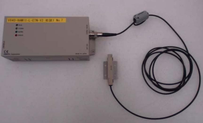
E4EV640HAM11LV2
Apr 13, 2015Carrier ID Reader/Writer (RFID)
Equipment Class
DXX - Part 15 Low Power Communication Device Transmitter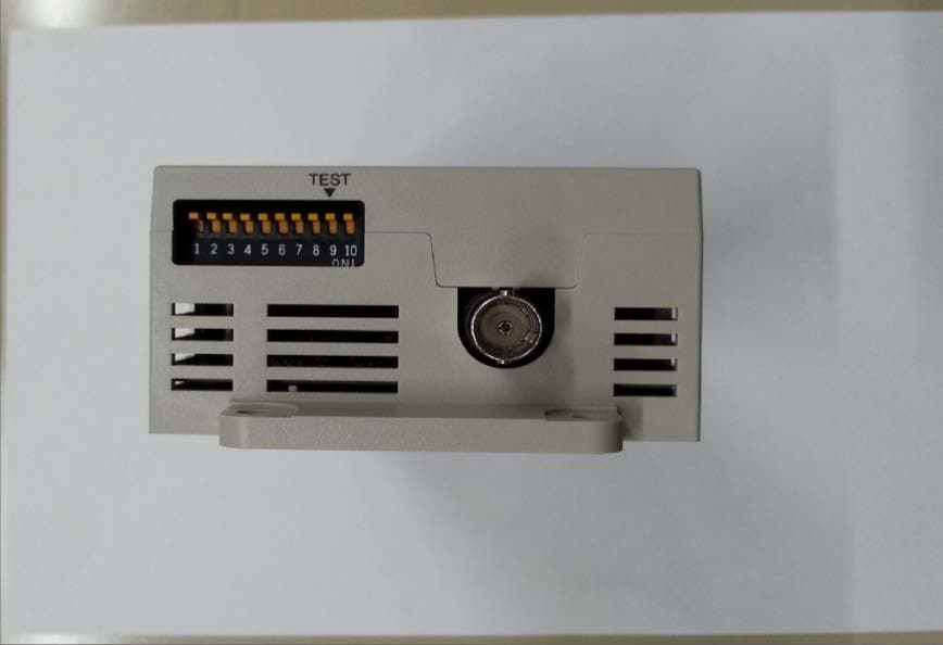
E4EV640HAM11V2
Apr 13, 2015Carrier ID Reader/Writer (RFID)
Equipment Class
DXX - Part 15 Low Power Communication Device Transmitter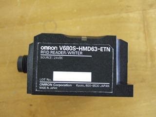
E4EV680S63
Nov 13, 2014Radio Frequency Identification System (RFID System)
Equipment Class
DXX - Part 15 Low Power Communication Device Transmitter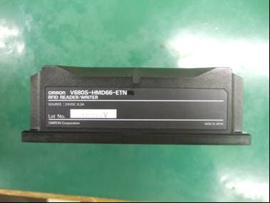
E4EV680S66
Apr 04, 2013Radio Frequency Identification System (RFID System)
Equipment Class
DXX - Part 15 Low Power Communication Device Transmitter