E4E6CYSID4S2V0106Kanban Reader (RFID system)
Omron Corporation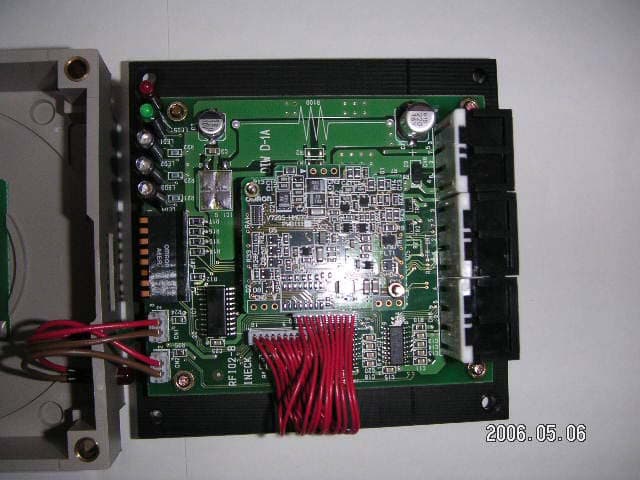
Click to zoom
Application Details
- Equipment Class
- DXX - Part 15 Low Power Communication Device Transmitter
- Date of Grant
- May 25, 2006
- Application Purpose
- Original Equipment
- Date of Application
- May 25, 2006
- Equipment Note
- Kanban Reader (RFID system)
- Frequency Range
- 13.56000000 - 13.56000000
- Company
- Omron Corporation
- Country
- Japan
Documents & Files
Document Text
Text extracted from the exhibit documents filed with the FCC. Open a document above to read the original.
Users Manual
1 Kanban Reader RFID System Model 4S2VR-V720-KR11 Series Operation Manual Omron Corporation Extensive Area Sales Department Information Product Section March, 2005 Version 2 <Record of Manual Revision> Jan. 9, 2004 Chapter 1 1-2 Rewriting of example of use Chapter 2 2-1 Revision of Hoshiden connector type Chapter 3 3-1 Addition of description of indicator function Chapter 4 4-1 Revision on time chart Jan. 13, 2004 Chapter 1 1-2 Rewriting of example of use Chapter 3 3-1 Revision on system configuration April 1, 2004 Chapter 2 2-1 Revision on mounting hole Chapter 4 4-5 Addition of Note 4-7 Addition of Note Chapter 5 5-2 Correction of description of ADR number in ASCII April 14, 2004 Chapter 2 2-4 Addition of omitted communication conditions June 9, 2004 Chapter 2 2-6 Addition of specification of connecting cable June 28, 2004 Chapter 1 1-2 Rewriting of example of use Chapter 2 2-1 Addition of outside layout diagram 2-5 Addition of dimensional outline drawing Chapter 3 3-2 Revision on layout of communication area diagram Chapter 6 6-4 Addition of omitted description of mutual interference condition June 30, 2004 P.13 P.17 Revision of typographical errors July 2, 2004 Chapter 2 2-5 Revision and addition of dimensional outline drawing July 7, 2004 Chapter 2 2-1 Revision of parts description 2-6-2 Revision of note of cable diagram July 13, 2004 Chapter 2 Change of item name July 28, 2004 Chapter 2 2-6-4 Addition of description of shield wire processing Nov. 10, 2004 Chapter 2 2-2 Revision of general specification, specification, ambient temperature 3 Introduction Thank you very much for purchasing our Kanban Reader Model 4S2VR-V720-KR11 Series. Model 4S2VR-V720-KR11 Series is a product developed with advanced technology and accumulated experiences of Omron. This Operation Manual includes important information on functions, performance and operating method required for using Model 4S2VR-V720-KR11 Series. In operating Model 4S2VR-V720-KR11 Series, observe the following instructions. • Read and understand this Operation Manual before starting operation. • Save this Manual with care for future reference. Notes to Users When this product is used in the following conditions and environment, care should be used to take safety measures such as failsafe provision and use with sufficient allowance in rating and performance, and contact sales personnel of Omron to assure safe and proper operation. 1. Use of the product in conditions and environment not specified in the Operation Manual. 2. Use of the product with equipment for nuclear control, railroad, aviation, vehicle, fuel system, medical equipment, entertainment devices and safety equipment 3. Use of the product for application which may have a major impact on a human life and property, and application requiring special safety. For Safe Operation Be sure to observe the following instructions to assure safety. 1. Do not use the product in the presence of inflammable, explosive and corrosive gas. 2. Do not attempt to disassemble, repair or remodel the product. 3. Tighten the base securing screws and terminal screws securely. 4. Use crimping terminals of the specified size for wiring. 5. Make sure that a cable or the like having a lock mechanism is securely locked before operation. 6. Ensure that the DC power supply unit meets the following requirements. 1) It should be exclusively used for 4S2VR V720-KR11 and not be connected to other machines and equipment. 2) The power supply meets the rating of supply voltage (within 5V±5% DC). 7. Observe warnings, cautions and notes included in this manual. Correct Way to Use 1. Avoid the following places in installing Model 4S2VR V720-KR11 . • Place subjected to direct sunlight • Place subjected to high humidity and dew condensation • Place where the main body of the device is subjected to direct vibration and impacts. 2. Prior checking on operating environment This product uses the frequency band of 13.56MHz and make communications with the tag. The frequency band of 13.56MHz is also used for the ISM band (One of frequencies assigned to medical equipment and 4 industrial heating devices: Generally an application for approval is required before installation). Consequently, if such equipment is present nearby, communication with the tag may be affected and the tag may be damaged. In case that this product is used near such equipment, check the effects of such equipment in advance. Observe the following instructions so as to minimize the effects of general noises. • Connect metallic bodies located around this product to Class D grounding (Class 3 grounding). • Do not install wiring close to high voltage and heavy current. 5 Contents Chapter 1 Overview of Equipment 1-1 Features 1-2 Example of Use of Kanban Reader Chapter 2 Specifications 2-1 Part Names and Functions 2-2 General Specifications 2-3 Performance Specifications 2-4 Interface Specifications (RS232C/RS422: To be switched) 2-5 Dimensional Outline Drawing 2-6 Cable Connection Diagram Chapter 3 Performance 3-1 System Configuration 3-2 Maximum Communication Range 3-3 Communication Time Chapter 4 Functions 4-1 Procedure of Communication and Outline of Operation 4-2 Memory Map of Tag 4-3 Specification of Access Page 4-4 Specification of Communication Mode 4-5 Types of Commands 4-6 Status 4-7 Exit Code Chapter 5 Communication Frame 5-1 Overview of Communication Frame 5-2 Command format (When the communication mode with the host is the realtime mode) 5-3 Command format (When the communication mode with the host is the polling mode) Chapter 6 Cautions in Operation 6-1 Effects of Metal on The Back Face upon Communication Area of Reader 6-2 Effects of Supply Voltage on Communication Area of Reader (For reference) 6-3 Cautions in handling of tag 6-4 Mutual Interference 6-5 Specifications of Tags 6-6 Warranty 6-7 Notice 6 Chapter 1 Overview of Equipment 1-1 Features 1. Model 4S2VR-V720-KR11 allows communication with the tag Model 4S2VR-V720-D13P series (Om…
Text truncated - open the document above for the full version.
Users Manual
21 Model 4S2VR-V720-KR11 vs Model 4S2VR-V720-D13P02ST 01020-10304050 60 70 - 20 - 30 - 40 - 50 - 60 - 70 10 70 60 50 40 30 20 ( mm) X Y X Y 01020-10304050 60 70 - 20 - 30 - 40 - 50 - 60 - 70 10 70 60 50 40 30 20 ( mm) X Y 01020-10304050 60 70 - 20 - 30 - 40 - 50 - 60 - 70 10 70 60 50 40 30 20 ( mm) X Y X Y X Y X Y Model 4S2VR-V720-KR11 vs Model 4S2VR-V720-D13P06ST 010 20 -10 30 40 50 60 70 - 20 - 30 - 40 - 50 - 60 - 70 10 70 60 50 40 30 20 ( mm) X Y X Y 010 20 -10 30 40 50 60 70 - 20 - 30 - 40 - 50 - 60 - 70 10 70 60 50 40 30 20 ( mm) X Y 010 20 -10 30 40 50 60 70 - 20 - 30 - 40 - 50 - 60 - 70 10 70 60 50 40 30 20 ( mm) X Y X Y X Y X Y 22 3-3 Communication Time HOST Command 4S2VR-V720-KR11 Ta g Command Response Response Command Command 2 Response Response Ta g Transmission time TAT Transmission time and TAT (Turn Around Time) is displayed below as the communication time. HOST KR11 Ta g RF interface TAT is the sum of (host communication time + RF interface communication time + processing time of controller). Since the baud rate is 9600bps, compute the host communication time for the length of the communication frame of command and response (byte), letting 1 byte=2ms. The processing time of the controller (for two communication times) is shorter enough to be ignored, compared with the communication time. The RF interface communication time is described below. The RF interface communication time refers to the transmission processing time between the reader and tag. This processing time varies in accordance with the number of pages to be read and written and specified method. z When the number of pages to be read and written are continuously specified. Calculating formula Read Write N: Number of pages to be processed z When the number of pages to be read and written are not specified continuously. Calculating formula Read Write N R : Largest specified page number - Smallest specified page number) N w : Number of pages to be written T=1.3N R +6.0 T=12.3N W +1.3N R +15.5 T=1.3N+6.0 T=13.6N+15.5 Command Command Transmission time (ms) Transmission time (ms) 23 Chapter 4 Functions 4-1 Procedure of Communication and Outline of Operation HOST KR11 Command Response V720 series tag When the host issues a command to Model 4S2VR-V720-KR11 , Model 4S2VR-V720-KR11 communicates with the tag according to the command and returns a response to the host. A command specifies: 1) page of the tag to be accessed "Specification of Access Page (4-3)" 2) communication procedure to be used "Specification of Communication mode (4-4)" 3) what to do "Specification of Command (4-5)" As a response, the result of execution of the command added with a message of an exit code is returned to the host "Exit Code (4-7) ". As a result of communication of 4S2VR-V720-KR11 with the tag, the OK or NG LED display lights up for about 1 second. In addition, the host can present its judgment such as judgment on checking of read data by flashing the LED display on the terminal, Model 4S2VR-V720-KR11 , for about 2 seconds (See the diagram below). Data exchange between the host and Model 4S2VR-V720-KR11 is executed smoothly by exchanging status information with each other. "Response Status of Command (4-6)" (In case that KR11 makes a judgment and displays it) HOST KR11 (OK display) 1S (NG display) (OK output) (NG output) (In case that reading is OK and the host displays its judgment based on the read data) HOST KR11 (OK display) (NG display) (OK output) (NG output) Command Response Continued light-up Flashing for 2 seconds (0.2/0.2s) In case of OK In case of NG Execution of communication Command Response Judgment (OK output) (NG output) Execution of communication 24 4-2 Memory Map of Tag Kanban reader Model 4S2VR-V720-KR11 can have access to banks O - F, 16 pages per bank, and 4 bytes per page. Each tag has a user memory area of 4 bytes per page, and 112 byte for 28 pages as shown in the memory map below. A user can use all the area freely for reading and writing for each page. When an area out of the memory for the tag is accessed, the tag absence error occurs. When I = Code II. ··· ··· ··· ··· ··· ··· 25 4-3 Specification of Access Page As described in the previous section, the communication between Model 4S2VR-V720-KR11 and the tag is executed by access for each page. The commands of Read, Write, Same Data Write and Write Protect are executed by specifying applicable pages. • Since more than one bank cannot be specified at a time, the area accessible at a time is limited to 16 pages or less in the same bank. • To specify a bank, the bank number is specified by the 2 digit hex number ((00) h - (OF) h). • To specify a page, the lowest number of applicable pages is specified by bits as shown below. The description is given by the 4-digit hex number. • On the communication-frame, a total of 6 hex digits for bank and page specification are represented according to ASCII. F Page specification Bank specification 2 1 0 2 digits 4 digits 26 4-4 Specification of Communication Mode A communication mode optimum for object motion according to the intended application is selected. The specification of the communication mode is represented by ASCII digits. Transmission operation No. Description Trigger ‘0’ When the host puts object movement under control, a command is issued after ensuring that the tag is present before Model 4S2VR-V720-KR11 . Immediately after receiving the command, the Kanban reader 4S2VR-V720-KR11 communicates with the tag and sends a response. If the tag is not present, a tag absence error is transmitted. After sending the response, the reader stands by for a new command. It is essential that one tag is present in the communication area. Auto ‘1’ When the host puts object motion under control mostly, and if a command has been issued in advance when the tag is approaching the Kanban reader 4S2VR-V720-KR11 , transmission is made when the tag comes into the communication area. After completing the transmission and…
Text truncated - open the document above for the full version.
External Photos
Front Back Top Right side Bottom Left side
ID Label/Location Info
2005-05-08OMRONH.OtsukaDesigned Design for: 4S2VR-V720-KR11B Sheet 1 / 1 DRWG No: 3rd Angle 2005-05-08OMRONH.Otsuka Title: FCC Label Design SCALE : Approved OMRON Corporation This device complies with Part 15 of the FCC Rules. Operation is subject to the following two conditions: (1) this device may not cause harmful interference, and(2) this device must accept any interference received, including interference that may cause undesired operation. FCC ID: E4E6CYSID4S2V0106 2005-05-08OMRONH.OtsukaDesigned Design for: 4S2VR-V720-KR11B Sheet 1 / 1 DRWG No: 3rd Angle 2005-05-08OMRONH.Otsuka Title: FCC Label Position SCALE : Approved OMRON Corporation This device complies with Part 15 of the FCC Rules. Operation is subject to th e following two conditions: (1) this device may not cause harmful interference, and(2) this device must accept any interference received, including interference that may cause undesired operation. FCC ID: E4E6CYSID4S2V0106 Label position of Right side
Test Report
Test report No. : 26IE0050-HO-A Page : 2 of 22 Issued date :April 28, 2006 FCC ID : E4E6CYSID4S2V0106 UL Apex Co., Ltd. Head Office EMC Lab. 4383-326 Asama-cho, Ise-shi, Mie-ken 516-0021 JAPAN Telephone : +81 596 24 8116 Facsimile : +81 596 24 8124 MF060b(19.04.06) CONTENTS PAGE SECTION 1: Client information............................................................................................................ 3 SECTION 2: Equipment under test (E.U.T.) .......................................................................................3 SECTION 3: Test specification, procedures & results ........................................................................ 4 SECTION 4: Operation of E.U.T. during testing.................................................................................7 SECTION 5: Conducted emission ......................................................................................................... 9 SECTION 6: Radiated emission (Fundamental , Spurious Emission and Spectrum Mask ) ........ 10 SECTION 7: -20dB Bandwidth ........................................................................................................... 11 SECTION 8: 99% Occupied Bandwidth ............................................................................................ 11 SECTION 9: Frequency Tolerance ..................................................................................................... 11 APPENDIX 1: Photographs of test setup............................................................................................ 12 Conducted emission..............................................................................................................12 Radiated emission.................................................................................................................13 Worst Case Position (Z-axis) ...............................................................................................14 APPENDIX 2: Test instruments .......................................................................................................... 15 APPENDIX 3: Data of EMI test .......................................................................................................... 16 Conducted emission..............................................................................................................16 Radiated emission (Spurious emission : below 30MHz) ...................................................18 Radiated emission (Spurious emission: above 30MHz) ....................................................19 –20dB Bandwidth .................................................................................................................20 99% Occpied Bandwidth .....................................................................................................21 Frequency Tolerance............................................................................................................22 Test report No. : 26IE0050-HO-A Page : 3 of 22 Issued date :April 28, 2006 FCC ID : E4E6CYSID4S2V0106 UL Apex Co., Ltd. Head Office EMC Lab. 4383-326 Asama-cho, Ise-shi, Mie-ken 516-0021 JAPAN Telephone : +81 596 24 8116 Facsimile : +81 596 24 8124 MF060b(19.04.06) SECTION 1: Client information Company Name : OMRON Corporation Brand or Trade name : OMRON Address : Gatecity Ohsaki,West tower 14F,1-11-1,Ohsaki,Shinagawa-ku,Tokyo,141-0032 Japan Telephone Number : +81-3-5435-2063 Facsimile Number : +81-3-5435-9415 Contact Person : Hiroshi Otsuka SECTION 2: Equipment under test (E.U.T.) 2.1 Identification of E.U.T. Type of Equipment : Kanban Reader (RFID System) Model No. : 4S2VR-V720-KR11B Serial No. : B0254 Country of Manufacture : Japan Receipt Date of Sample : March 14, 2006 Condition of EUT : Production model (Not for Sale: This sample is equivalent to mass-produced items.) Modification of EUT : No modification by the test lab 2.2 Product Description Model No: 4S2VR-V720-KR11B is the Kanban Reader (RFID System). The clock frequency of EUT is 25MHz (CPU). Equipment Type : Transceiver Frequency band : 13.553-13.567 MHz Frequency of Operation : 13.56 MHz Type of modulation : ASK (Bit rate:26.4803KBPS) Power control : No Mode of operation : Simplex Antenna Type : PWB Pattern Antenna Method of Frequency Generation : Crystal Operating voltage : DC5.0V +/-0.25 Test report No. : 26IE0050-HO-A Page : 4 of 22 Issued date :April 28, 2006 FCC ID : E4E6CYSID4S2V0106 UL Apex Co., Ltd. Head Office EMC Lab. 4383-326 Asama-cho, Ise-shi, Mie-ken 516-0021 JAPAN Telephone : +81 596 24 8116 Facsimile : +81 596 24 8124 MF060b(19.04.06) SECTION 3: Test specification, procedures & results 3.1 Test Specification Test Specification : FCC Part15 Subpart C : 2006 Title : FCC 47CFR Part15 Radio Frequency Device Subpart C Intentional Radiators Section 15.207 Conducted limits Section 15.225 : Operation within the band 13.110-14.010MHz FCC 15.31 (e) Testing of the variation of the input power (85% and 115% of DC5.0V) was performed. Please refer to the Page 22 for details. FCC Part 15.203 Antenna requirement It is impossible for end users to replace the antenna, because the antenna is mounted inside of the EUT. Therefore, the equipment complies with the antenna requirement of Section 15.203. 3.2 Procedures and results No. Item Test Procedure Specification Remarks Deviation Worst margin Results 1 Conducted emission ANSI C63.4:2003 7. AC powerline conducted emission measurements Section 15.207 - N/A 8.1dB 0.25638MHz N, AV Complied 2 Electric Field Strength of Fundamental Emission ANSI C63.4:2003 13. Measurement of intentional radiators Section 15.225(a) Radiated N/A 74.9dB 13.56000MHz Complied 3 Spectrum Mask ANSI C63.4:2003 13. Measurement of intentional radiators Section 15.225(b)(c) Radiated N/A 42.8dB 12.71100MHz, QP Complied 4 -20dB Bandwidth ANSI C63.4:2003 13. Measurement of intentional radiators Section15.215(c) Radiated N/A See data Complied 5 Electric Field Strength of Spurious Emission ANSI C63.…
Text truncated - open the document above for the full version.
Test Setup Photos
Test report No. : 26IE0050-HO-A Page : 12 of 22 Issued date :April 28, 2006 FCC ID : E4E6CYSID4S2V0106 UL Apex Co., Ltd. Head Office EMC Lab. 4383-326 Asama-cho, Ise-shi, Mie-ken 516-0021 JAPAN Telephone : +81 596 24 8116 Facsimile : +81 596 24 8124 MF060b(19.04.06) APPENDIX 1: Photographs of test setup Conducted emission Front Rear Test report No. : 26IE0050-HO-A Page : 13 of 22 Issued date :April 28, 2006 FCC ID : E4E6CYSID4S2V0106 UL Apex Co., Ltd. Head Office EMC Lab. 4383-326 Asama-cho, Ise-shi, Mie-ken 516-0021 JAPAN Telephone : +81 596 24 8116 Facsimile : +81 596 24 8124 MF060b(19.04.06) Radiated emission Front Rear Test report No. : 26IE0050-HO-A Page : 14 of 22 Issued date :April 28, 2006 FCC ID : E4E6CYSID4S2V0106 UL Apex Co., Ltd. Head Office EMC Lab. 4383-326 Asama-cho, Ise-shi, Mie-ken 516-0021 JAPAN Telephone : +81 596 24 8116 Facsimile : +81 596 24 8124 MF060b(19.04.06) Worst Case Position (Z-axis) X-axis Y-axis Z-axis
Contact Information
Applicant
Koji Shimada
Technical Contact
UL Apex Co., LtdMakoto Kosaka
[email protected]81-596-24-8116
4383-326 Asama-cho · Ise-shi, Mie-ken · Japan
Non-Technical Contact
UL Apex Co., LtdYoshiko Mizuta
[email protected]81-596-24-8116
Test Firm
UL Japan, Inc.Mitsuru Fujimura
Technical Specifications
| # | Rule Parts | Frequency Range | Power Output |
|---|---|---|---|
| 1 | 15C | 13.56 MHz - 13.56 MHz | - |
Other Applications from Omron Corporation
E4EV640HAM13
Apr 22, 2026RFID Amplifier Unit
Equipment Class
DCD - Part 15 Low Power Transmitter Below 1705 kHz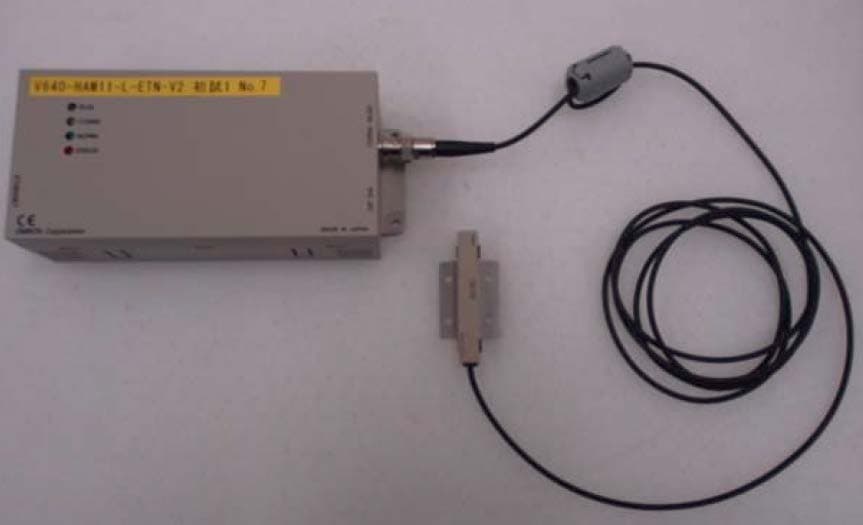
E4EV640HAM11LV2
Apr 13, 2015Carrier ID Reader/Writer (RFID)
Equipment Class
DXX - Part 15 Low Power Communication Device Transmitter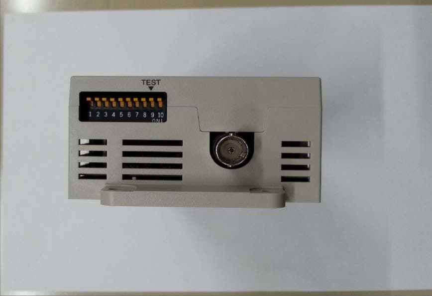
E4EV640HAM11V2
Apr 13, 2015Carrier ID Reader/Writer (RFID)
Equipment Class
DXX - Part 15 Low Power Communication Device Transmitter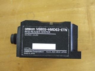
E4EV680S63
Nov 13, 2014Radio Frequency Identification System (RFID System)
Equipment Class
DXX - Part 15 Low Power Communication Device Transmitter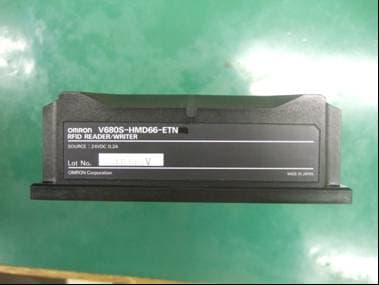
E4EV680S66
Apr 04, 2013Radio Frequency Identification System (RFID System)
Equipment Class
DXX - Part 15 Low Power Communication Device Transmitter