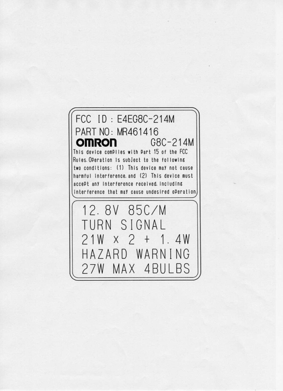
E4EG8C-214M
Omron Corporation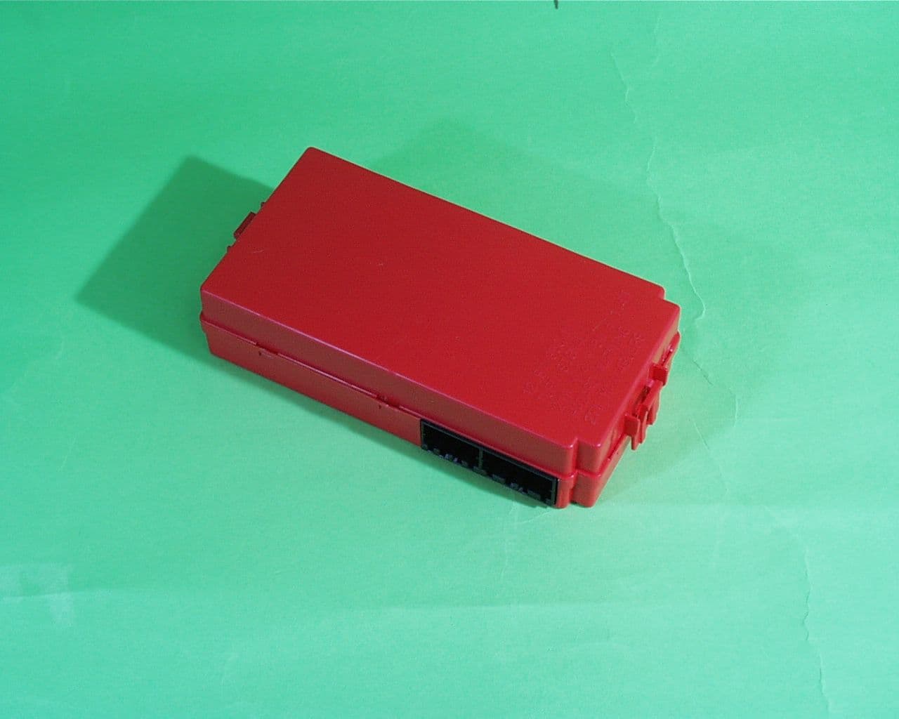
Click to zoom
Application Details
- Equipment Class
- CRR - Superregenerative Receiver
- Date of Grant
- Oct 31, 2000
- Application Purpose
- Original Equipment
- Date of Application
- Oct 12, 1999
- Frequency Range
- 315.00000000 - 315.00000000
- Company
- Omron Corporation
- Country
- Japan
Documents & Files

Document Text
Text extracted from the exhibit documents filed with the FCC. Open a document above to read the original.
Test Report
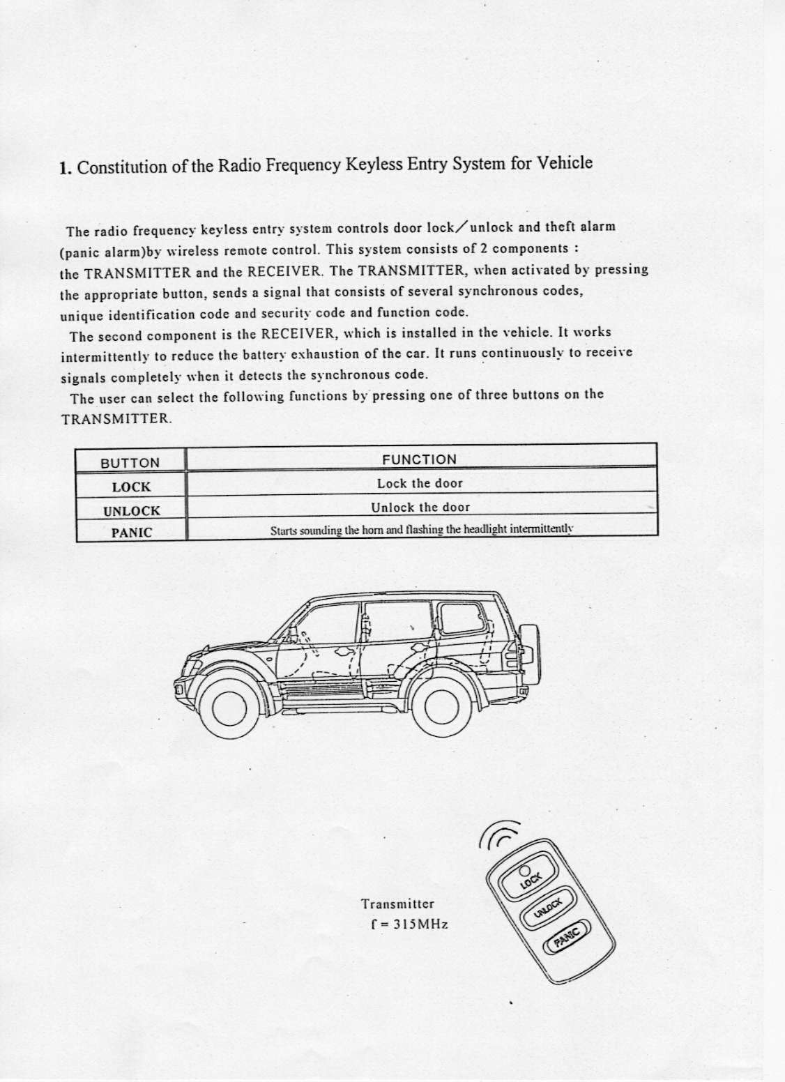
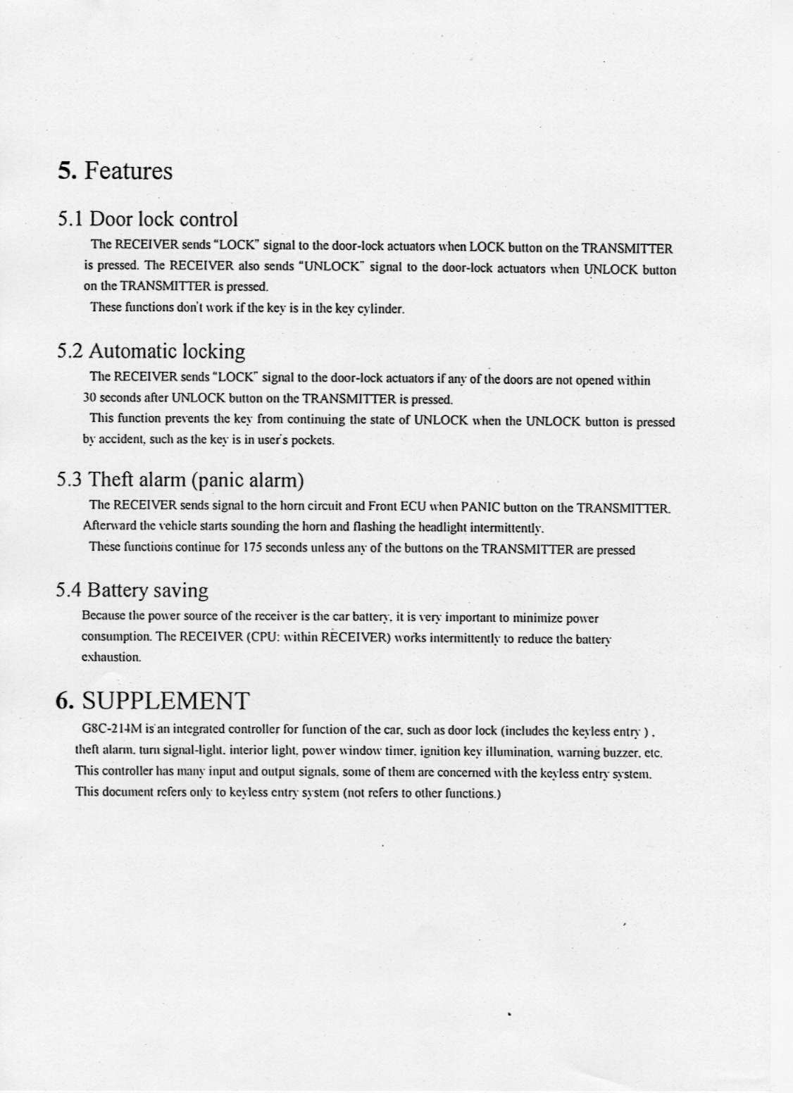
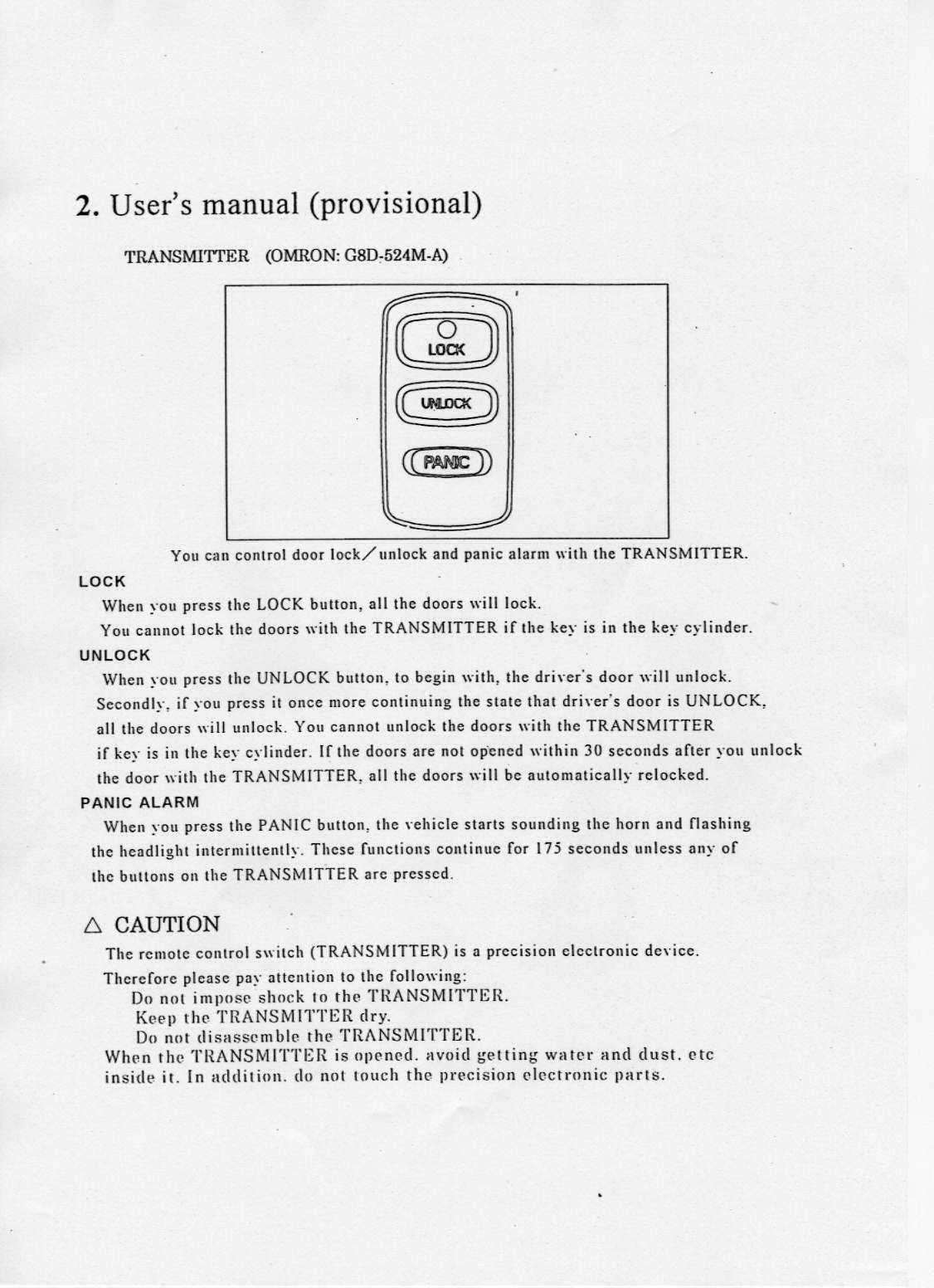
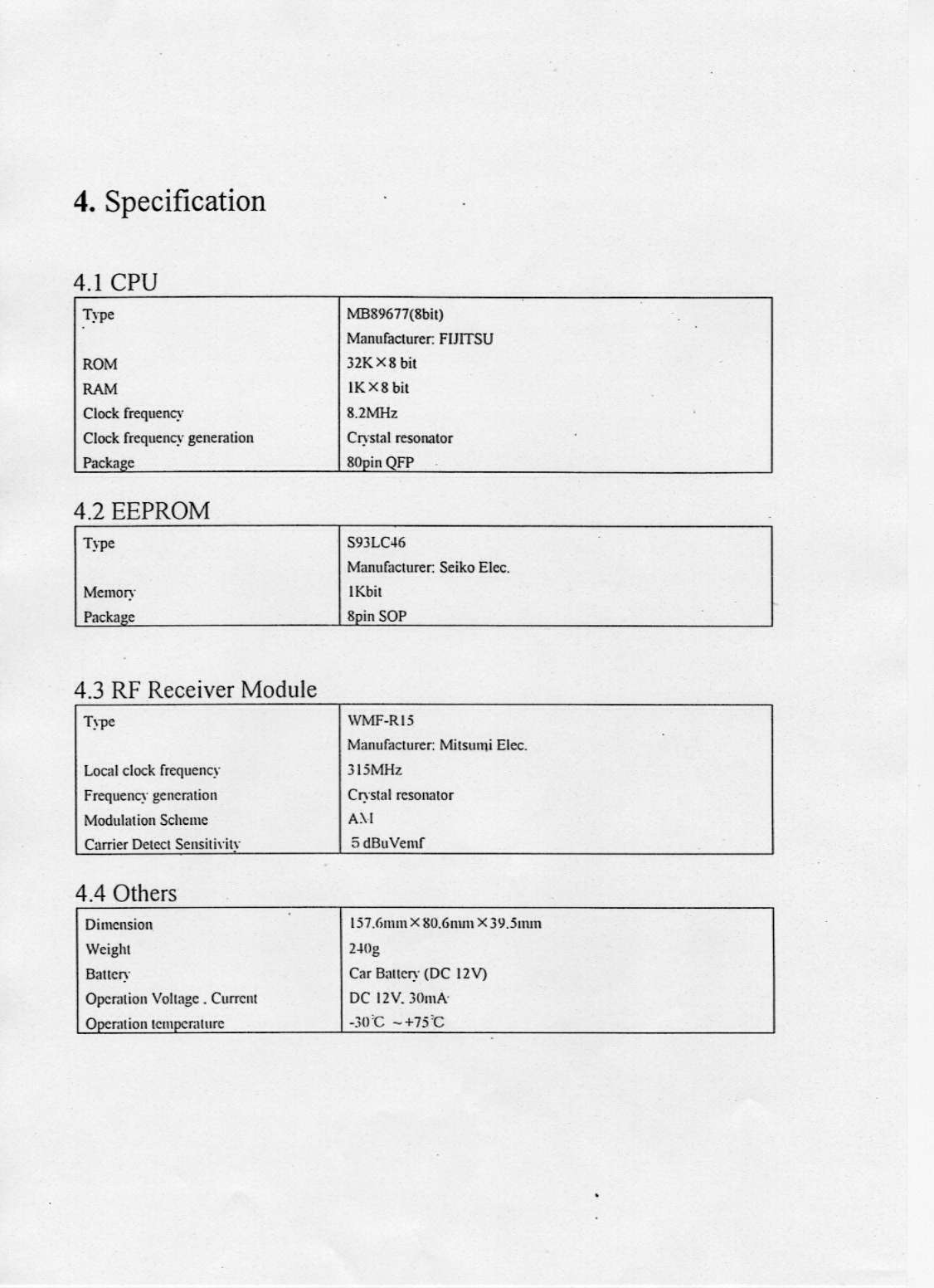
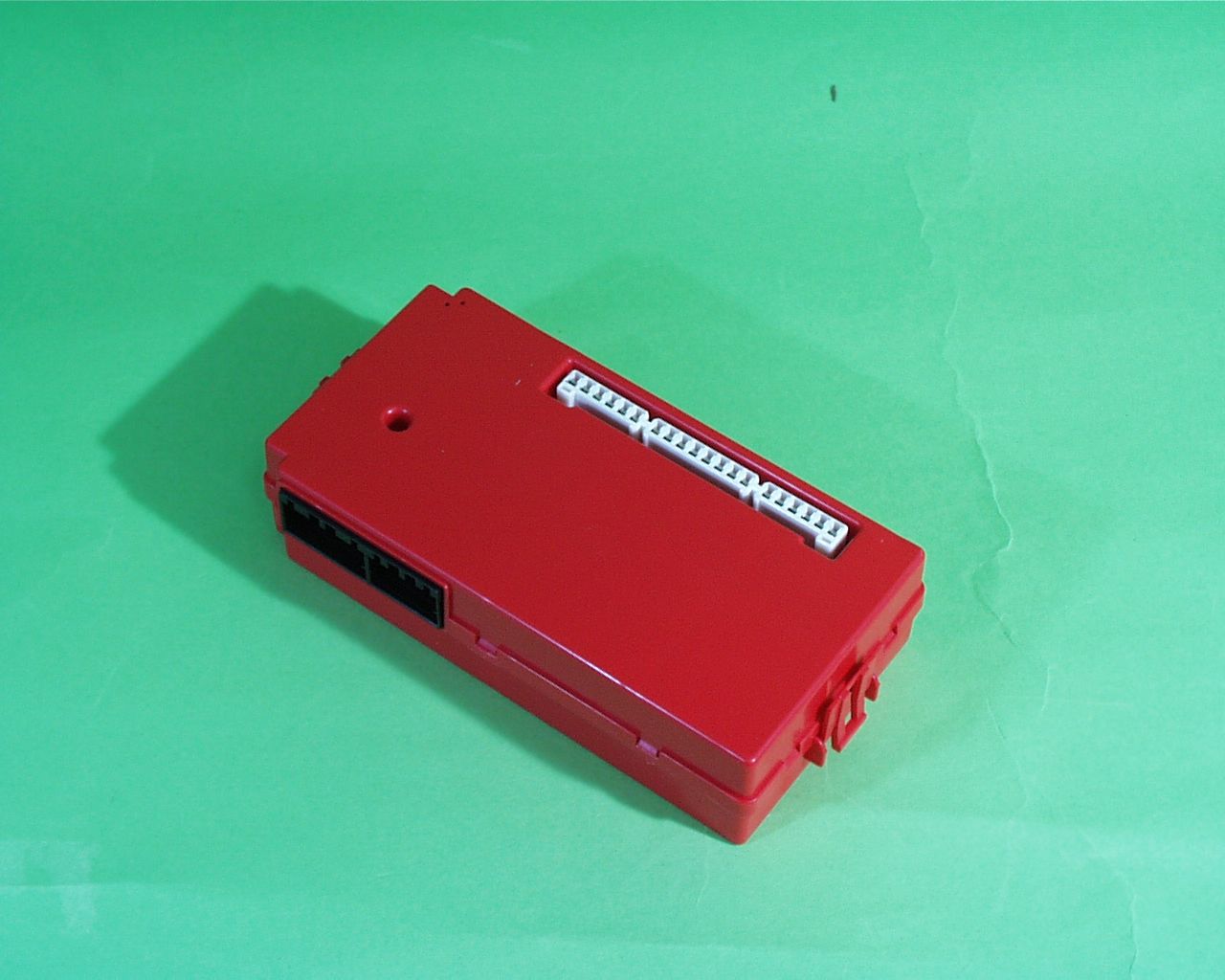
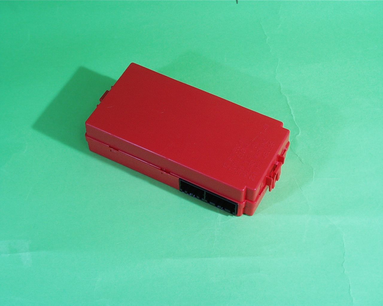
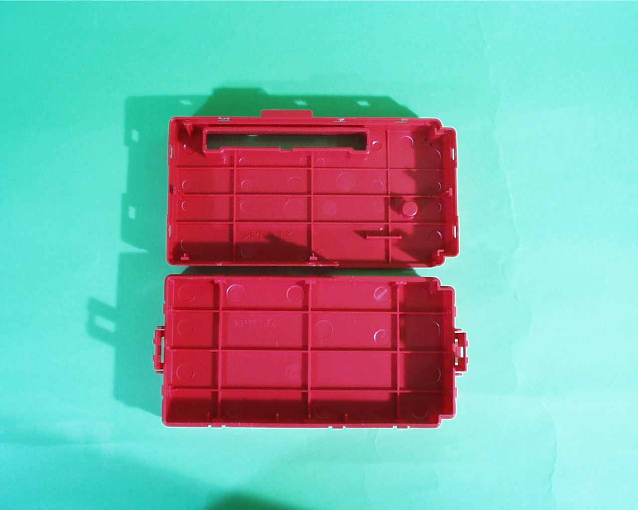
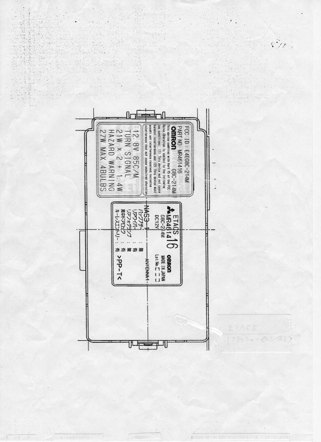
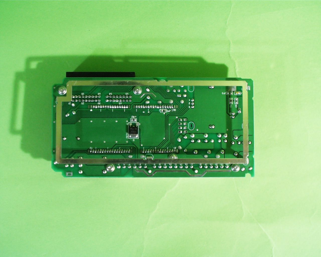
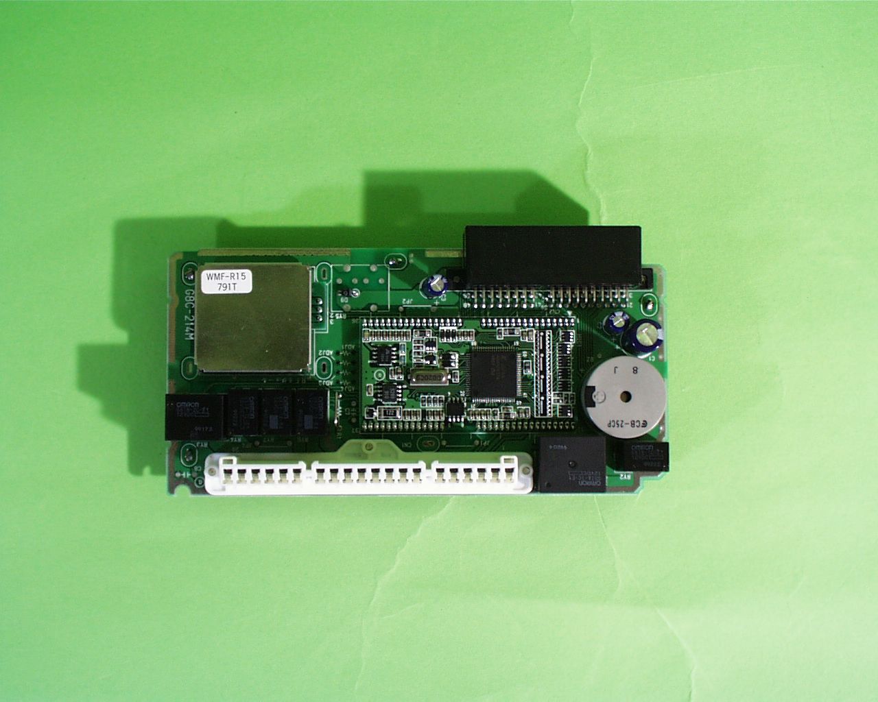
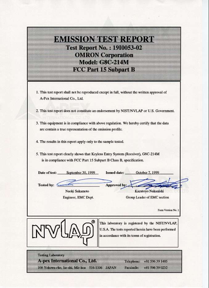
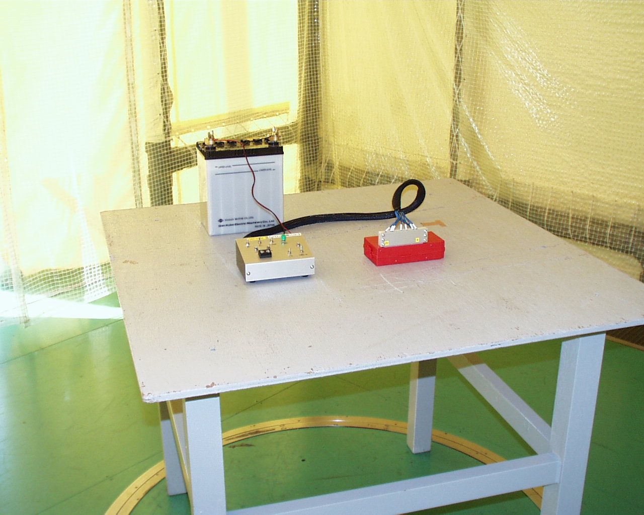
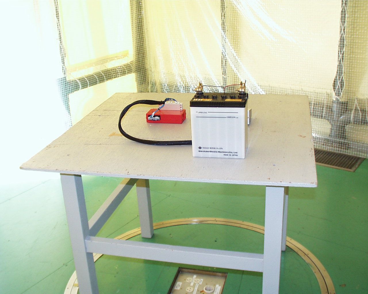
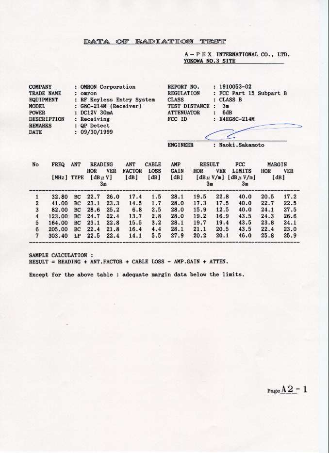
Testing Laboratory A-pex International Co., Ltd.Telephone:+81 596 39 1485 108 Yokowa-cho, Ise-shi, Mie-ken 516-1106 JAPAN Facsimile:+81 596 39 0232 This laboratory is registered by the NIST/NVLAP, U.S.A. The tests reported herein have been performed in accordance with its terms of registration. EMISSION TEST REPORT Test Report No. : 19I0053-02 OMRON Corporation Model: G8C-214M FCC Part 15 Subpart B 1. This test report shall not be reproduced except in full, without the written approval of A-Pex International Co., Ltd. 2. This test report does not constitute an endorsement by NIST/NVLAP or U.S. Government. 3. This equipment is in compliance with above regulation. We hereby certify that the data are contain a true representation of the emission profile. 4. The results in this report apply only to the sample tested. 5. This test report clearly shows that Keyless Entry System (Receiver), G8C-214M is in compliance with FCC Part 15 Subpart B Class B, specification. Date of test: September 30, 1999 Issued date: October 7, 1999 Tested by: Approved by: Naoki SakamotoKazutoyo Nakanishi Engineer, EMC Dept. Group Leader of EMC section Form Version No. 1 Test report FCC ID : E4EG8C-214M Our reference : 19I0053-02 Page: 2 of 15 Issued date: 99-10-07 Testing Laboratory A-pex International Co., Ltd.Telephone:+81 596 39 1485 108 Yokowa-cho, Ise-shi, Mie-ken 516-1106 JAPANFacsimile:+81 596 39 0232 Table of Contents Page 1 GENERAL INFORMATION3 1.1 Product Description4 1.2 Tested System Details4 1.3 Tested Methodology5 1.4 Test Facility5 2 SYSTEM TEST CONFIGURATION6 2. 1 Operation Environment 6 2.2 Justification6 2. 3 EUT Exercise Software6 2.4 Test Procedure7 Figure 2.1 Configuration of Tested System8 3 RADIATED MEASUREMENT PHOTOS10 Figure 3.1 Radiated Measurement Photos10 3.1 Measurement Uncertainty11 4 RADIATED EMISSION DATA12 4.1 Field Strength Calculation13 5 TEST EQUIPMENT USED14 APPENDIX15 A:Test Data A1 - A2 Test report FCC ID : E4EG8C-214M Our reference : 19I0053-02 Page: 3 of 15 Issued date: 99-10-07 Testing Laboratory A-pex International Co., Ltd.Telephone:+81 596 39 1485 108 Yokowa-cho, Ise-shi, Mie-ken 516-1106 JAPANFacsimile:+81 596 39 0232 1 GENERAL INFORMATION APPLICANT: OMRON Corporation ADDRESS: 1-501, Yashirogaoka, Meito-ku, Nagoya-city Aichi, 465-0051 Japan Tel: +81-52-704-2525 Fax: +81-52-704-2769 REGULATION(S): FCC Part 15 Subpart B, Class B MODEL NUMBER: G8C-214M SERIAL NUMBER: - KIND OF EQUIPMENT: Keyless Entry System (Receiver) TESTED DATE: September 30, 1999 RECEIPT DATE OF SAMPLE : September 24, 1999 TEST REPORT NUMBER: 19I0053-02 TEST SITE: A-PEX Yokowa NO.3 Open Test Site Test report FCC ID : E4EG8C-214M Our reference : 19I0053-02 Page: 4 of 15 Issued date: 99-10-07 Testing Laboratory A-pex International Co., Ltd.Telephone:+81 596 39 1485 108 Yokowa-cho, Ise-shi, Mie-ken 516-1106 JAPANFacsimile:+81 596 39 0232 1.1 Product Description OMRON Corporation, Model G8C-214M (referred to as the EUT in this report) is a Keyless Entry System (Receiver). The specification is as following : Operation Frequency: 8.2MHz Local Clock Frequency : 315MHz Operation Voltage: DC 12V, 30mA 1.2 Tested System Details The FCC IDs for all equipment, plus description of all cables used in the tested system are: Model FCC ID Description Cable description Backshell Material (1) OMRONE4EG8C-214MKeyless Entry System Unshielded I/F CableP.V.C. M/N: G8C-214M (Receiver) Unshielded DC Power CableP.V.C. S/N: - (EUT) (2) OMRONE4EG8D-522M-AKeyless Entry System - - M/N: G8D-522M-A (Transmitter) S/N: - (3) OMRONN/A Simulator - - M/N: - S/N: - (4) Shin-kobe Electric N/A Battery - - Machinery Co., Ltd. M/N: 38 B/9R S/N: - Test report FCC ID : E4EG8C-214M Our reference : 19I0053-02 Page: 5 of 15 Issued date: 99-10-07 Testing Laboratory A-pex International Co., Ltd.Telephone:+81 596 39 1485 108 Yokowa-cho, Ise-shi, Mie-ken 516-1106 JAPANFacsimile:+81 596 39 0232 1.3 Tested Methodology Both conducted and radiated testing were performed according to the procedures in FCC/ANSI C63.4(1992). Radiated testing was performed at a distance of 3 meters from the antenna to EUT. 1.4 Test Facility The open area test site and conducted measurement facility used to collect the radiated data is located at 108 Yokowa-cho, Ise-shi, Mie-ken 516-1106 Japan. This site has been fully described in a report dated Aug. 1, 1997 submitted to FCC office, and Listed dated Sep. 16, 1997 (31040/SIT 1300F2). Test report FCC ID : E4EG8C-214M Our reference : 19I0053-02 Page: 6 of 15 Issued date: 99-10-07 Testing Laboratory A-pex International Co., Ltd.Telephone:+81 596 39 1485 108 Yokowa-cho, Ise-shi, Mie-ken 516-1106 JAPANFacsimile:+81 596 39 0232 2 SYSTEM TEST CONFIGURATION 2.1 Operation Environment Radiation Temperature : 26 Degree Humidity: 55% Power supply : DC 12V 2.2 Justification The system was configured in typical fashion (as a customer would normally use it) for testing. 2.3 EUT Exercise Software The EUT exercise program used during radiated and conducted testing was designed to exercise the various system components in a manner similar to typical use. The sequence is used: Operation: Receiving mode Test report FCC ID : E4EG8C-214M Our reference : 19I0053-02 Page: 7 of 15 Issued date: 99-10-07 Testing Laboratory A-pex International Co., Ltd.Telephone:+81 596 39 1485 108 Yokowa-cho, Ise-shi, Mie-ken 516-1106 JAPANFacsimile:+81 596 39 0232 2.4 Test Procedure 2.4.1 Tabletop Equipment Radiated Emissions EUT was placed on a platform of nominal size, 1m by 1.5m, raised 80cm above the conducting ground plane. The rear of EUT, including peripherals was aligned and flush with rear of tabletop. I/O cables that were connected to the peripherals were bundled in center. They were folded back and forth forming a bundle 30cm to 40cm long and were hanged 40cm height to the ground plane. Test was made with the antenna positioned in both the horizontal and vertical planes of polarization. The measurement antenna was varied in height above the conducting ground p…
Text truncated - open the document above for the full version.
Contact Information
Applicant
Koji Shimada
Technical Contact
A-Pex International Co., Ltd.Naoki Sakamoto
[email protected]+81-596-39-1485
108 Yokowa-cho · Ise-shi · Japan
Non-Technical Contact
A-Pex International Co., Ltd.Momo Tsukamoto
[email protected]+81-596-39-1485
Test Firm
UL Japan, Inc.Kazunori Nishimura
Technical Specifications
| # | Rule Parts | Frequency Range | Power Output |
|---|---|---|---|
| 1 | 15B | 315 MHz - 315 MHz | - |
Other Applications from Omron Corporation
E4EV640HAM13
Apr 22, 2026RFID Amplifier Unit
Equipment Class
DCD - Part 15 Low Power Transmitter Below 1705 kHz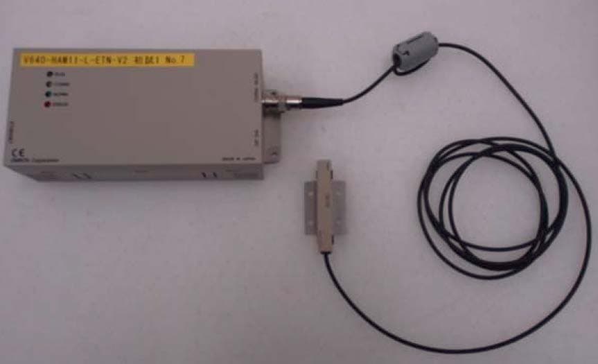
E4EV640HAM11LV2
Apr 13, 2015Carrier ID Reader/Writer (RFID)
Equipment Class
DXX - Part 15 Low Power Communication Device Transmitter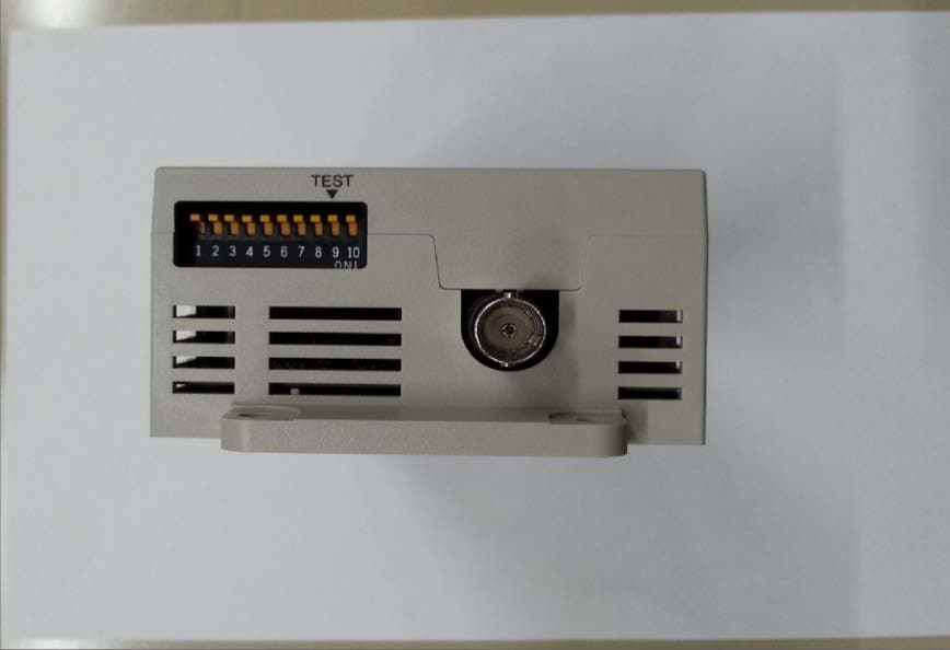
E4EV640HAM11V2
Apr 13, 2015Carrier ID Reader/Writer (RFID)
Equipment Class
DXX - Part 15 Low Power Communication Device Transmitter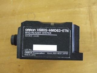
E4EV680S63
Nov 13, 2014Radio Frequency Identification System (RFID System)
Equipment Class
DXX - Part 15 Low Power Communication Device Transmitter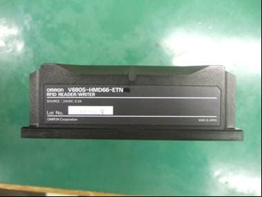
E4EV680S66
Apr 04, 2013Radio Frequency Identification System (RFID System)
Equipment Class
DXX - Part 15 Low Power Communication Device Transmitter