E4EV640HAM11Carrier ID Reader/Writer (RFID)
Omron Corporation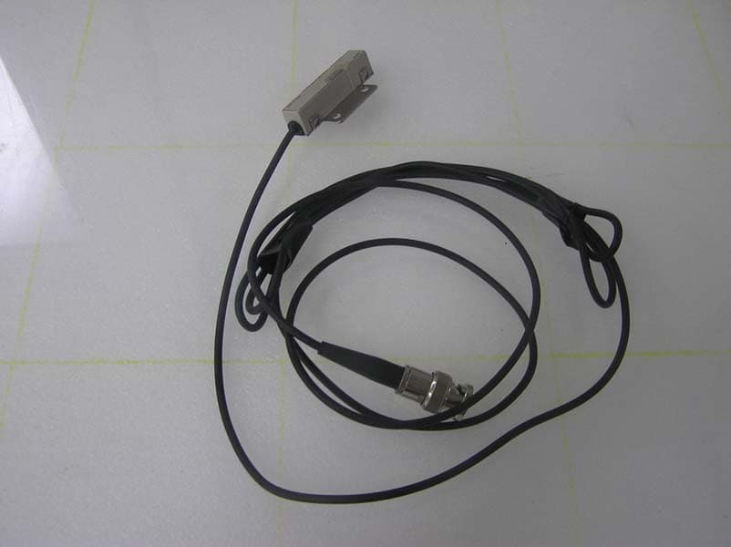
Click to zoom
Application Details
- Equipment Class
- DCD - Part 15 Low Power Transmitter Below 1705 kHz
- Date of Grant
- Sep 29, 2010
- Application Purpose
- Original Equipment
- Date of Application
- Sep 28, 2010
- Equipment Note
- Carrier ID Reader/Writer (RFID)
- Frequency Range
- 0.13420000 - 0.13420000
- Company
- Omron Corporation
- Country
- Japan
Documents & Files
Document Text
Text extracted from the exhibit documents filed with the FCC. Open a document above to read the original.
Users Manual
CIDRW SYSTEM V640 SERIES USER'S MANUAL Cat. No. Z308-E1-01 AMPLIFIER UNITS V640-HAM11-ETN V640-HAM11-L-ETN CIDRW HEADS V640-HS61 V640-HS62 Introduction Thank you for purchasing the V640-series CIDRW System. Please observe the following points when operating the V640-series CIDRW System: • Please read and understand the contents of this manual before using the system. • After reading this manual, store it in a convenient location for easy reference whenever necessary. ÇÕǹÇ?Ç ëÊ 1 èÕ ëÊ 2 èÕ ëÊ 3 èÕ ëÊ 4 èÕ INTRODUCTION SECTION 1 SECTION 2 SECTION 3 SECTION 4 SECTION 5 SECTION 6 SECTION 7 Introduction SECTION 1 SECTION 2 SECTION 3 SECTION 4 SECTION 5 SECTION 6 SECTION 7 Table of Contents/Precautions in Using the Products Product Outline Installation and Connections/Wiring Preparing for Communications Reading from/Writing to ID Tags Browser Interface Troubleshooting CIDRW System V640-HAM11-ETNAmplifier Unit V640-HAM11-L-ETNAmplifier Unit V640-HS61CIDRW Head V640-HS62CIDRW Head User's Manual Appendix 2 INTRODUCTION Precautions in using the product CIDRW System User’s Manual INTRODUCTION READ AND UNDERSTAND THIS DOCUMENT Please read and understand this document before using the products. Please consult your OMRON representative if you have any questions or comments. WARRANTY OMRON’s exclusive warranty is that the products are free from defects in materials and workmanship for a period of one year (or other period if specified) from date of sale by OMRON. OMRON MAKES NO WARRANTY OR REPRESENTATION, EXPRESS OR IMPLIED, REGARDING NON- INFRINGEMENT, MERCHANTABILITY, OR FITNESS FOR PARTICULAR PURPOSE OF THE PRODUCTS. ANY BUYER OR USER ACKNOWLEDGES THAT THE BUYER OR USER ALONE HAS DETERMINED THAT THE PRODUCTS WILL SUITABLY MEET THE REQUIREMENTS OF THEIR INTENDED USE. OMRON DISCLAIMS ALL OTHER WARRANTIES, EXPRESS OR IMPLIED. LIMITATIONS OF LIABILITY OMRON SHALL NOT BE RESPONSIBLE FOR SPECIAL, INDIRECT, OR CONSEQUENTIAL DAMAGES, LOSS OF PROFITS OR COMMERCIAL LOSS IN ANY WAY CONNECTED WITH THE PRODUCTS, WHETHER SUCH CLAIM IS BASED ON CONTRACT, WARRANTY, NEGLIGENCE, OR STRICT LIABILITY. In no event shall responsibility of OMRON for any act exceed the individual price of the product on which liability is asserted. IN NO EVENT SHALL OMRON BE RESPONSIBLE FOR WARRANTY, REPAIR, OR OTHER CLAIMS REGARDING THE PRODUCTS UNLESS OMRON’S ANALYSIS CONFIRMS THAT THE PRODUCTS WERE PROPERLY HANDLED, STORED, INSTALLED, AND MAINTAINED AND NOT SUBJECT TO CONTAMINATION, ABUSE, MISUSE, OR INAPPROPRIATE MODIFICATION OR REPAIR. SUITABILITY FOR USE THE PRODUCTS CONTAINED IN THIS DOCUMENT ARE NOT SAFETY RATED. THEY ARE NOT DESIGNED OR RATED FOR ENSURING SAFETY OF PERSONS, AND SHOULD NOT BE RELIED UPON AS A SAFETY COMPONENT OR PROTECTIVE DEVICE FOR SUCH PURPOSES. Please refer to separate catalogs for OMRON's safety rated products. OMRON shall not be responsible for conformity with any standards, codes, or regulations that apply to the combination of products in the customer’s application or use of the product. At the customer’s request, OMRON will provide applicable third party certification documents identifying ratings and limitations of use that apply to the products. This information by itself is not sufficient for a complete determination of the suitability of the products in combination with the end product, machine, system, or other application or use. The following are some examples of applications for which particular attention must be given. This is not intended to be an exhaustive list of all possible uses of the products, nor is it intended to imply that the uses listed may be suitable for the products: • Outdoor use, uses involving potential chemical contamination or electrical interference, or conditions or uses not described in this document. • Nuclear energy control systems, combustion systems, railroad systems, aviation systems, medical equipment, amusement machines, vehicles, safety equipment, and installations subject to separate industry or government regulations. • Systems, machines, and equipment that could present a risk to life or property. Please know and observe all prohibitions of use applicable to the products. NEVER USE THE PRODUCTS FOR AN APPLICATION INVOLVING SERIOUS RISK TO LIFE OR PROPERTY WITHOUT ENSURING THAT THE SYSTEM AS A WHOLE HAS BEEN DESIGNED TO ADDRESS THE RISKS, AND THAT THE OMRON PRODUCT IS PROPERLY RATED AND INSTALLED FOR THE INTENDED USE WITHIN THE OVERALL EQUIPMENT OR SYSTEM. 3 CIDRW System User’s Manual INTRODUCTION Precautions in using the product INTRODUCTION PERFORMANCE DATA Performance data given in this document is provided as a guide for the user in determining suitability and does not constitute a warranty. It may represent the result of OMRON’s test conditions, and the users must correlate it to actual application requirements. Actual performance is subject to the OMRON Warranty and Limitations of Liability. CHANGE IN SPECIFICATIONS Product specifications and accessories may be changed at any time based on improvements and other reasons. It is our practice to change model numbers when published ratings or features are changed, or when significant construction changes are made. However, some specifications of the product may be changed without any notice. When in doubt, special model numbers may be assigned to fix or establish key specifications for your application on your request. Please consult with your OMRON representative at any time to confirm actual specifications of purchased products. DIMENSIONS AND WEIGHTS Dimensions and weights are nominal and are not to be used for manufacturing purposes, even when tolerances are shown. ERRORS AND OMISSIONS The information in this document has been carefully checked and is believed to be accurate; however, no responsibility is assumed for clerical, typographical, or proofreading errors, or omissions. PROGRAMMABLE PRODUCTS OMRON shall not be responsible for the user’s programming of a programmable product, or any consequence the…
Text truncated - open the document above for the full version.
Users Manual
CIDRW SYSTEM V640 SERIES USER'S MANUAL Cat. No. Z307-E1-01 AMPLIFIER UNITS V640-HAM11-V3 V640-HAM11-L CIDRW HEADS V640-HS61 V640-HS62 CIDRW CONTROLLER V700-L22 LINK UNIT V700-L11 Introduction Thank you for purchasing the V640-series CIDRW System. Please observe the following points when operating the V640-series CIDRW System: • Please read and understand the contents of this manual before using the system. • After reading this manual, store it in a convenient location for easy reference whenever necessary. ÇÕǹÇ?Ç ëÊ 1 èÕ ëÊ 2 èÕ ëÊ 3 èÕ ëÊ 4 èÕ INTRODUCTION SECTION 1 SECTION 2 SECTION 3 SECTION 4 SECTION 5 SECTION 6 Introduction SECTION 1 SECTION 2 SECTION 3 SECTION 4 SECTION 5 SECTION 6 Table of Contents/Precautions in Using the Products Product Outline Installation and Connections/Wiring Preparing for Communications Reading from/Writing to ID Tags Troubleshooting Appendix CIDRW System V640-HAM11-V3Amplifier Unit V640-HAM11-LAmplifier Unit V640-HS61CIDRW Head V640-HS62CIDRW Head V700-L22CIDRW Controller V700-L11Link Unit User's Manual 2 INTRODUCTION Precautions in using the product CIDRW System User’s Manual INTRODUCTION READ AND UNDERSTAND THIS DOCUMENT Please read and understand this document before using the products. Please consult your OMRON representative if you have any questions or comments. WARRANTY OMRON’s exclusive warranty is that the products are free from defects in materials and workmanship for a period of one year (or other period if specified) from date of sale by OMRON. OMRON MAKES NO WARRANTY OR REPRESENTATION, EXPRESS OR IMPLIED, REGARDING NON- INFRINGEMENT, MERCHANTABILITY, OR FITNESS FOR PARTICULAR PURPOSE OF THE PRODUCTS. ANY BUYER OR USER ACKNOWLEDGES THAT THE BUYER OR USER ALONE HAS DETERMINED THAT THE PRODUCTS WILL SUITABLY MEET THE REQUIREMENTS OF THEIR INTENDED USE. OMRON DISCLAIMS ALL OTHER WARRANTIES, EXPRESS OR IMPLIED. LIMITATIONS OF LIABILITY OMRON SHALL NOT BE RESPONSIBLE FOR SPECIAL, INDIRECT, OR CONSEQUENTIAL DAMAGES, LOSS OF PROFITS OR COMMERCIAL LOSS IN ANY WAY CONNECTED WITH THE PRODUCTS, WHETHER SUCH CLAIM IS BASED ON CONTRACT, WARRANTY, NEGLIGENCE, OR STRICT LIABILITY. In no event shall responsibility of OMRON for any act exceed the individual price of the product on which liability is asserted. IN NO EVENT SHALL OMRON BE RESPONSIBLE FOR WARRANTY, REPAIR, OR OTHER CLAIMS REGARDING THE PRODUCTS UNLESS OMRON’S ANALYSIS CONFIRMS THAT THE PRODUCTS WERE PROPERLY HANDLED, STORED, INSTALLED, AND MAINTAINED AND NOT SUBJECT TO CONTAMINATION, ABUSE, MISUSE, OR INAPPROPRIATE MODIFICATION OR REPAIR. SUITABILITY FOR USE THE PRODUCTS CONTAINED IN THIS DOCUMENT ARE NOT SAFETY RATED. THEY ARE NOT DESIGNED OR RATED FOR ENSURING SAFETY OF PERSONS, AND SHOULD NOT BE RELIED UPON AS A SAFETY COMPONENT OR PROTECTIVE DEVICE FOR SUCH PURPOSES. Please refer to separate catalogs for OMRON's safety rated products. OMRON shall not be responsible for conformity with any standards, codes, or regulations that apply to the combination of products in the customer’s application or use of the product. At the customer’s request, OMRON will provide applicable third party certification documents identifying ratings and limitations of use that apply to the products. This information by itself is not sufficient for a complete determination of the suitability of the products in combination with the end product, machine, system, or other application or use. The following are some examples of applications for which particular attention must be given. This is not intended to be an exhaustive list of all possible uses of the products, nor is it intended to imply that the uses listed may be suitable for the products: • Outdoor use, uses involving potential chemical contamination or electrical interference, or conditions or uses not described in this document. • Nuclear energy control systems, combustion systems, railroad systems, aviation systems, medical equipment, amusement machines, vehicles, safety equipment, and installations subject to separate industry or government regulations. • Systems, machines, and equipment that could present a risk to life or property. Please know and observe all prohibitions of use applicable to the products. NEVER USE THE PRODUCTS FOR AN APPLICATION INVOLVING SERIOUS RISK TO LIFE OR PROPERTY WITHOUT ENSURING THAT THE SYSTEM AS A WHOLE HAS BEEN DESIGNED TO ADDRESS THE RISKS, AND THAT THE OMRON PRODUCT IS PROPERLY RATED AND INSTALLED FOR THE INTENDED USE WITHIN THE OVERALL EQUIPMENT OR SYSTEM. 3 CIDRW System User’s Manual INTRODUCTION Precautions in using the product INTRODUCTION PERFORMANCE DATA Performance data given in this document is provided as a guide for the user in determining suitability and does not constitute a warranty. It may represent the result of OMRON’s test conditions, and the users must correlate it to actual application requirements. Actual performance is subject to the OMRON Warranty and Limitations of Liability. CHANGE IN SPECIFICATIONS Product specifications and accessories may be changed at any time based on improvements and other reasons. It is our practice to change model numbers when published ratings or features are changed, or when significant construction changes are made. However, some specifications of the product may be changed without any notice. When in doubt, special model numbers may be assigned to fix or establish key specifications for your application on your request. Please consult with your OMRON representative at any time to confirm actual specifications of purchased products. DIMENSIONS AND WEIGHTS Dimensions and weights are nominal and are not to be used for manufacturing purposes, even when tolerances are shown. ERRORS AND OMISSIONS The information in this document has been carefully checked and is believed to be accurate; however, no responsibility is assumed for clerical, typographical, or proofreading errors, or omissions. PROGRAMMABLE PRODUCTS OMRON shall not be responsible for the user’s programming of a prog…
Text truncated - open the document above for the full version.
Users Manual
SECTION 6 Troubleshooting 69 CIDRW System User’s Manual SECTION 6 Troubleshooting Troubleshooting70 70 SECTION 6 Troubleshooting CIDRW System User’s Manual SECTION 6 Troubleshooting Troubleshooting Errors are indicated by the presence or absence of a response to an Amplifier Unit command, and by the indicators. List of Error Messages Amplifier Unit Indicators Type Response code NameDescription Host communi- cations error 14Format errorThere is a mistake in the command format. (For example, the com- mand portion is undefined, or the page or address specification is inappropriate.) Communications error between the CIDRW Head and ID Tag 70Communications error Noise or another hindrance has occurred during communications with an ID Tag, and communications cannot be completed normally. 71Verification errorCorrect data cannot be written to an ID Tag. 72No Tag errorEither there is no ID Tag in front of the CIDRW Head, or the CIDRW Head is unable to detect the ID Tag due to environmental factors (e.g., noise). 7BOutside write area error The ID Tag is at a position where reading is possible but writing is not, so writing does not complete normally. 7EID system error (1)The ID Tag is in a status where it cannot execute the command pro- cessing. 7FID system error (2)An inapplicable ID Tag has been used. CPU hardware error 9AHardware error in CPU An error occurred when writing to EEPROM. NameIndications RUN (green)Turns ON when the Amplifier Unit is in normal operation. COMM (orange)Turns ON during communications with the host device or during communications with an ID Tag. NORM (green)Turns ON when the communications finish with no error. ERROR (red)Turns ON when an error occurs during communications with the host device, or during communications with an ID Tag. CIDRW System User’s Manual SECTION 6 Troubleshooting SECTION 6 Troubleshooting 71 Operation Check Flowchart ■From Installation to Trial Operation Errors are indicated by whether or not a response to the test command is received and by the status of the Amplifier Unit indicators. • If the Test Command Was Received Normally: Indicators RUNCOMMNORMERROR Response Code for the Response Type Response code Function Normal 00The command was received normally. Error occurrence Test command transmission RUN indicator OFF? No Ye s An error has occurred at the Amplifier Unit. Amplifier Unit error Refer to page 72. Check if the Amplifier Unit settings are correct. If There Is No Response to the Command: Refer to page 72. Response received? Ye s Check the nature of the response. If there is a response to the command Refer to page 72. No (Lights once) 72 SECTION 6 Troubleshooting CIDRW System User’s Manual SECTION 6 Troubleshooting • Amplifier Unit Error Check the status of the indicators after transmission of the test command. After taking appropriate corrective action, restart the Amplifier Unit, send the test command again and check again. • If There Is No Response to the Command: Check the status of the indicators after transmission of the test command. After taking appropriate corrective action, restart the Amplifier Unit, send the test command again and check again. • If There Is a Response to the Command: Check the status of the indicators after transmission of the test command. After taking appropriate corrective action, restart the Amplifier Unit, send the test command again and check again. RUNCOMMNORMERRORMain check points — (If RUN is OFF, the status of the other indica- tors can be ignored.) • Influence of background noise (change installation position) • Amplifier Unit power supply If the error cannot be resolved after checking, the Amplifier Unit may be damaged. RUNCOMMNORMERRORMain check points • Amplifier Unit baud rate settings • Node numbers of the Amplifier Units (do not match the node number in the test command) • Connection and wiring of the cable between the host device and Amplifier Unit • Routing of each cable (influence of background noise) If the error cannot be resolved after checking, the Amplifier Unit may be damaged. • Amplifier Unit baud rate settings • Connection and wiring of the cable between the host device and Amplifier Unit • Routing of the cables (influence of background noise) RUNCOMMNORMERRORMain check points • Node numbers of the Amplifier Units (The same number is set for more than one Unit) If the error cannot be resolved after checking, the Amplifier Unit may be damaged. There is a mistake in the command format (number of charac- ters, character code, etc.). (Lights once) (Lights once) CIDRW System User’s Manual SECTION 6 Troubleshooting SECTION 6 Troubleshooting 73 ■From Trial Operation to Communications Errors are indicated by the status of the indicators after transmission of the write command, and by the response code of the response. • If the ID Tag Was Processed Normally: If there is no response to the write command, refer to the From Installation to Trial Operation, Operation Check Flowchart. Refer to page 71. Indicators RUNCOMMNORMERROR Response Code for the Response Type Response code Function Normal00The ID Tag was processed normally. Error occurrence Is the response code 1? No Ye s Check the command format. If the response code is 1 Refer to page 74. Ye s Communications with the ID Tag has failed. If the response code is 7 Refer to page 74. Write command sent RUN indicator OFF? No Ye s An error has occurred at the Amplifier Unit. Amplifier Unit error Refer to page 74. Is the response code 7? Communications OK No (Lights once) (Lights once) 74 SECTION 6 Troubleshooting CIDRW System User’s Manual SECTION 6 Troubleshooting • Amplifier Unit Error Check the status of the indicators after transmission of the command. After taking appropriate correc- tive action, send the write command again and check again. • If the Response Code is 1 : There is a host device communications error. Check the status of the indicators and the response code of the response after transmission of the command. After taking approp…
Text truncated - open the document above for the full version.
Users Manual
SECTION 4 Reading from/Writing to ID Tags 69 CIDRW System User’s Manual SECTION 4 Reading from/Writing to ID Tags When SECS Is Used70 Online Check72 Get Attributes72 Set Attributes73 Read Data74 Write Data75 Read ID76 Write ID76 Subsystem Command (ChangeState)77 Subsystem Command (GetStatus)78 Subsystem Command (PerformDiagnostics)78 Subsystem Command (Reset)79 When SECS Is Not Used81 READ84 WRITE85 SAME WRITE87 BYTE WRITE88 TEST89 NAK90 GET PARAMETER90 GET LAST COMMAND92 GET COMMUNICATIONS HISTORY93 CLEAR COMMUNICATIONS HISTORY94 NOISE MEASUREMENT94 RESET94 70 SECTION 4 When SECS Is Used CIDRW System User’s Manual SECTION 4 Reading from/Writing to ID Tags When SECS Is Used The SEMI standards are subject to revision. You must refer to the actual standards. • SEMI E99 THE CARRIER ID READER/WRITER FUNCTIONAL STANDARD • SEMI E5 EQUIPMENT COMMUNICATION STANDARD 2 MESSAGE CONTENT (SECS II) • SEMI E4 EQUIPMENT COMMUNICATION STANDARD 1 MESSAGE TRANSFER (SECS I) SECS Protocol Specifications Refer to page 149. Message Specifications List of Error Messages Refer to page 96. List of Messages Used ClassificationSFDirectionSECS II namesSee General purpose messages 11 S,H→E,replyAre You There Requestp.72 12 S,H←EOn Line Datap.72 CIDRW system messages 181S,H→E,replyRead Attribute Requestp.72 182S,H←ERead Attribute Datap.72 183S,H→E,replyWrite Attribute Requestp.73 184S,H←EWrite Attribute Acknowledgep.73 185S,H→E,replyRead Requestp.74 186S,H←ERead Data p.74 187S,H→E,replyWrite Requestp.75 188S,H←EWrite Acknowledgep.75 189S,H→E,replyRead ID Requestp.76 1810S,H←ERead ID Data p.76 1811S,H→E,replyWrite ID Requestp.76 1812S,H←EWrite ID Acknowledgep.76 1813S,H→E,replySubsystem Command Requestp.77 1814S,H←ESubsystem Command Acknowledgep.77 Data Item Dictionary SECS II data itemsNameFormatValue ATTRIDAttribute ID20Attribute name ATTRVALAttribute value20Attribute value MIDCarrier IDMID20 16 to 7E16 (Visible ASCII) DATAData20All characters 00H-0FFH DATALENGTHDataSize52Offset designation: 1 to 224 Segment designation: Refer to ID Tag Memory Maps page 147. DATASEGDataSeg20Offset designation: "00", "01"..."0222", "0223" Segment designation: Refer to ID Tag Memory Maps page 147. STATUSPM information20"NE": Normally executed 71 CIDRW System User’s Manual SECTION 4 When SECS Is Used SECTION 4 Reading from/Writing to ID Tags *1: “PS” is an expansion command for this Unit. *2: When the TARGET ID is "00" (CIDRW), this is a zero length item. *3: "EE," "HE," and "TE" are used only with S18F6, S18F8, S18F10, and S18F12. S9F7 Responses An S9F7 response is given when a message in an illegal format is received from the host device. "Illegal format" here means that there is a problem with the message composition, such as illegal attributes, or insuffi- cient or too many items. If other problems relating to the item contents arise, the response is SSACK = "CE" (communi- cations error). Communications with the Host Device Communicate with the host device only after confirming that the CIDRW Controller has started. Also, unstable signals may occur at the host interface when the CIDRW Controller is started. When initializing operation, clear the reception buffer at the host device or take other suitable methods to clear unwanted signals. SSACKResult status20"NO": Normal "EE": Execution error *3 "CE": Communications error "HE": Hardware error *3 "TE": Tag error *3 List of STATUSStatusL,4 1.<PMInformation> 2.<AlarmStatus> 3.<OperationalStatus> 4.<HeadStatus> *2 The STATUS values are included in the PM infor- mation. CPVALState request 20"OP", "MT", "PS" *1 TARGETIDTarget ID20"00"-"31" "00" indicates the CIDRW Controller itself. SSCMDSubsystem com- mands 20"ChangeState" "GetStatus" "PerformDiagnostics" "Reset" Data Item Dictionary SECS II data itemsNameFormatValue 72 SECTION 4 When SECS Is Used CIDRW System User’s Manual SECTION 4 Reading from/Writing to ID Tags ■Specifications for Each Stream/Function • Online Check • Get Attributes S1,F1Are You There RequestS,H→E,reply Header only S1,F2On Line DataS,H←E L,2 1.<MDLN> 2.<SOFTREV> • Set MDLN (model number). • Set SOFTREV (software revision level). S18,F1Read Attribute RequestS,H→E,reply L,2 1.<TARGETID>"00"-"31" 2.L,n 1.<ATTRID1> ⋅ n.<ATTRIDn> • The setting for reading all attributes (CIDRW Controller or Heads) is n = 0. S18,F2Read Attribute DataS,H←E L,4 1.<TARGETID>"00"-"31" 2.<SSACK> 3.L,n 1.<ATTRVAL1> ⋅ n.<ATTRVALn> 4.L,s 1.<STATUS1> ⋅ s.<STATUSs> • The order of the attribute data corresponds to the attribute ID specified by S18, F1. When reading of all attributes is specified, unsupported attribute items (ATTRVAL) are omitted. • When the specified target is invalid: n = 0, s = 0, SSACK = "CE" communications error • When one or more undefined attributes are included: n = 0, s = 0, SSACK = "CE" communications error • When Head attributes are specified with TARGET = “00” or CIDRW Controller attributes are specified with TARGET <> “00”: n = 0, s = 0, SSACK = “CE” communications error • If the status of SSACK is other than "NO" (normal), the List of Status will comprise zero items. 73 CIDRW System User’s Manual SECTION 4 When SECS Is Used SECTION 4 Reading from/Writing to ID Tags • Set Attributes F18,F3Write Attribute RequestS,H→E,reply L,2 1.<TARGETID>"00" (fixed) 2.L,n 1.L,2 1.<ATTRID1> 2.<ATTRVAL1> n.L,2 1.<ATTRIDn> 2,<ATTRVALn> Since the attributes for Heads are all RO in this system, the target ID is fixed as “00”. S18,F4Write Attribute AcknowledgeS,H←E L,3 1.<TARGETID>"00" (fixed) 2.<SSACK> 3.L,s 1.<STATUS1> ⋅ s.<STATUSs> • When the specified target is invalid: s = 0, SSACK = "CE" communications error • When one or more undefined attributes or RO attributes are included: s = 0, SSACK = "CE" communications error • When illegal attribute data is specified: s = 0, SSACK = "CE" communications error • If the status of SSACK is other than "NO" (normal), the List of Status will comprise zero items. 74 SECTION 4 When SECS Is Used CIDRW System User’s Manual SECTION 4 Reading from/Writing t…
Text truncated - open the document above for the full version.
Cover Letter(s)
P1 CONFIDENTIAL B CONFIDENTIAL B Difference between V640-HAM11-V3 and V640-HAM11-ETN There is a difference of communication por t w i th a host between V640 -HAM11-V3 and V640-HAM11-ETN. ■ V640-HAM11-V3 ■ V640-HAM11-ET N RS232C, RS485 Ethernet In sid e o f V640-HAM11-ETN In sid e o f V640-HAM11-V3
External Photos
Antenna Photo Model: V640-HS61
External Photos
External Photo FCC ID: E4EV640HAM11 IC Numbe: 850J-V64HAM11 Model: V640-HAM11-ETN Front Rear External Photo FCC ID: E4EV640HAM11 IC Numbe: 850J-V64HAM11 Model: V640-HAM11-ETN Top Bottom External Photo FCC ID: E4EV640HAM11 IC Numbe: 850J-V64HAM11 Model: V640-HAM11-ETN Side 1 Side 2
External Photos
External Photo FCC ID: E4EV640HAM11 IC Number: 850J-V64HAM11 Model: V640-HAM11-V3 Front Rear External Photo FCC ID: E4EV640HAM11 IC Number: 850J-V64HAM11 Model: V640-HAM11-V3 Top Bottom External Photo FCC ID: E4EV640HAM11 IC Number: 850J-V64HAM11 Model: V640-HAM11-V3 Side 1 Side 2
Internal Photos
Internal Photo FCC ID: E4EV640HAM11 IC Numbe: 850J-V64HAM11 Model: V640-HAM11-ETN ※ This Carrier ID Reader/Writer (RFID)[V640-HAM11-ETN] consists of the board A [V640-HAM11-ETN_PCB(1)] and the board B[V640-HAM11-V3 PCB(2)]. Board A (V640-HAM11-ETN_PCB(1)) Front Rear Internal Photo FCC ID: E4EV640HAM11 IC Numbe: 850J-V64HAM11 Model: V640-HAM11-ETN Board B (V640-HAM11-V3 PCB(2)) Front Rear
Internal Photos
Internal Photo FCC ID: E4EV640HAM11 IC Number: 850J-V64HAM11 Model: V640-HAM11-V3 ※This Carrier ID Reader/Writer (RFID)[V640-HAM11-V3] consists of the board A [V640-HAM11-V3 PCB(1)] and the board B[V640-HAM11-V3 PCB(2)]. Board A (V640-HAM11-V3 PCB(1)) Front Rear Rear Internal Photo FCC ID: E4EV640HAM11 IC Number: 850J-V64HAM11 Model: V640-HAM11-V3 Board B(V640-HAM11-V3 PCB(2)) Front Rear
Test Report
Test report No. : 31AE0134-HO-01-A-R1 Page : 2 of 25 Issued date : September 9, 2010 Revised date : September 27, 2010 FCC ID : E4EV640HAM11 UL Japan, Inc. Head Office EMC Lab. 4383-326 Asama-cho, Ise-shi, Mie-ken 516-0021 JAPAN Telephone : +81 596 24 8116 Facsimile : +81 596 24 8124 CONTENTS PAGE SECTION 1: Customer information ..................................................................................................... 3 SECTION 2: Equipment under test (E.U.T.)........................................................................................ 3 SECTION 3: Test specification, procedures & results ........................................................................ 4 SECTION 4: Operation of E.U.T. during testing .................................................................................7 SECTION 5: Conducted Emission......................................................................................................... 9 SECTION 6: Radiated Emission (Fundamental and Spurious Emission) ....................................... 10 SECTION 7: -26dB Bandwidth............................................................................................................ 12 SECTION 8: 99% Occupied Bandwidth.............................................................................................12 APPENDIX 1: Photographs of test setup ............................................................................................ 13 Conducted Emission.......................................................................................................................... 13 Radiated Emission............................................................................................................................. 14 Worst Case Position .......................................................................................................................... 15 APPENDIX 2: Data of EMI test........................................................................................................... 17 Conducted Emission.......................................................................................................................... 17 Radiated Emission above 30MHz (Spurious Emission)................................................................. 21 -26dB Bandwidth and 99% Occupied Bandwidth ......................................................................... 23 APPENDIX 3: Test instruments .......................................................................................................... 25 Test report No. : 31AE0134-HO-01-A-R1 Page : 3 of 25 Issued date : September 9, 2010 Revised date : September 27, 2010 FCC ID : E4EV640HAM11 UL Japan, Inc. Head Office EMC Lab. 4383-326 Asama-cho, Ise-shi, Mie-ken 516-0021 JAPAN Telephone : +81 596 24 8116 Facsimile : +81 596 24 8124 SECTION 1: Customer information Company Name : OMRON Corporation Address : 2-2-1, Nishikusatsu, Kusatsu-city, Shiga-pref., 525-0035, Japan Telephone Number : +81-77-565-5287 Facsimile Number : +81-77-565-5569 Contact Person : Kazunori Morikawa SECTION 2: Equipment under test (E.U.T.) 2.1 Identification of E.U.T. Type of Equipment : Carrier ID Reader/Writer (RFID) Model No. : V640-HAM11-ETN Serial No. : Refer to Section 4, Clause 4.2 Rating : DC 24V Receipt Date of Sample : August 23, 2010 Country of Mass-production : Japan Condition of EUT : Production prototype Modification of EUT : No Modification by the test lab 2.2 Product Description General Specification Clock frequency(ies) in the system : 17.1776MHz, 8MHz, 50MHz Radio Specification Radio Type : Transceiver Frequency of Operation : 134.2 kHz Modulation : Amplitude Shift Keying Power Supply (radio part input) : DC 5V Antenna type : Loop Coil Antenna Similar model This EUT has similar model: V640-HAM11-V3. • V640-HAM11-ETN: EtherNet Communication type and Normal distance type • V640-HAM11-V3: Serial Communication type and Normal distance type There is no difference except for these. Test report No. : 31AE0134-HO-01-A-R1 Page : 4 of 25 Issued date : September 9, 2010 Revised date : September 27, 2010 FCC ID : E4EV640HAM11 UL Japan, Inc. Head Office EMC Lab. 4383-326 Asama-cho, Ise-shi, Mie-ken 516-0021 JAPAN Telephone : +81 596 24 8116 Facsimile : +81 596 24 8124 SECTION 3: Test specification, procedure…
Text truncated - open the document above for the full version.
Contact Information
Applicant
Koji Shimada
Technical Contact
UL Japan, Inc.Mitsuru Fujimura
[email protected]81-596-24-8116
4383-326 Asama-cho · Ise-shi, Mie-ken · Japan
Test Firm
UL Japan, Inc. Head office EMC Lab.Tetsuya Hashimoto
Technical Specifications
| # | Rule Parts | Frequency Range | Power Output |
|---|---|---|---|
| 1 | 15C | 0.1342 MHz - 0.1342 MHz | - |
Other Applications from Omron Corporation
E4EV640HAM13
Apr 22, 2026RFID Amplifier Unit
Equipment Class
DCD - Part 15 Low Power Transmitter Below 1705 kHz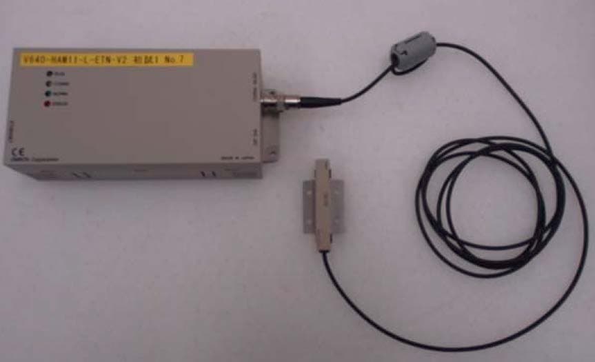
E4EV640HAM11LV2
Apr 13, 2015Carrier ID Reader/Writer (RFID)
Equipment Class
DXX - Part 15 Low Power Communication Device Transmitter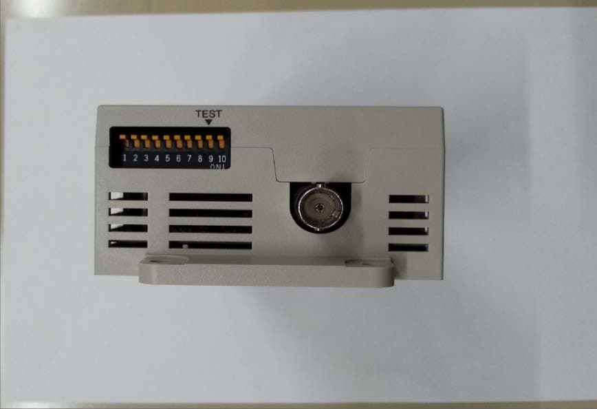
E4EV640HAM11V2
Apr 13, 2015Carrier ID Reader/Writer (RFID)
Equipment Class
DXX - Part 15 Low Power Communication Device Transmitter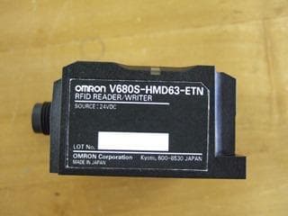
E4EV680S63
Nov 13, 2014Radio Frequency Identification System (RFID System)
Equipment Class
DXX - Part 15 Low Power Communication Device Transmitter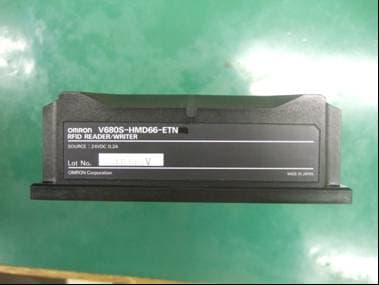
E4EV680S66
Apr 04, 2013Radio Frequency Identification System (RFID System)
Equipment Class
DXX - Part 15 Low Power Communication Device Transmitter