E4EV680S64Radio Frequency Identification System (RFID System)
Omron Corporation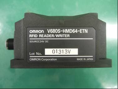
Click to zoom
Application Details
- Equipment Class
- DXX - Part 15 Low Power Communication Device Transmitter
- Date of Grant
- Apr 04, 2013
- Application Purpose
- Original Equipment
- Date of Application
- Apr 04, 2013
- Equipment Note
- Radio Frequency Identification System (RFID System)
- Frequency Range
- 13.56000000 - 13.56000000
- Company
- Omron Corporation
- Country
- Japan
Documents & Files
Document Text
Text extracted from the exhibit documents filed with the FCC. Open a document above to read the original.
Users Manual
V680S-HMD64-ETN 2013 Observe the following precautions to ensure safe usage of the product. 1. Installation and Storage Environment Do not install the Products near any equipment that generates a large amount of heat (such as heaters,transformers, and large-capacity resistors). If many Reader/Writer are mounted near each other, communications performance may decrease due to mutual interference. Refer to Reference Data in Section 7 Appendices of User’s Manual and check to make sure there is no mutual interference. 2. Installation and Removing Do not use the AC power supply. Do not perform wiring incorrectly. Doing so may result in rupture or damage from burning. PRECAUTIONS FOR SAFE USE 1. Installation and Storage Environment 2. Installation Securely tighten the screws to a torque of 1.2N m when mounting the reader/writer. Use a tightening torque of 0.3 to 0.49N m when mounting the cable connector. 3. Prohibitions 4. Maintenance PRECAUTIONS FOR CORRECT USE © OMRON Corporation All Rights Reserved. INSTRUCTION SHEET Thank you for selecting OMRON product. This sheet pri-marily describes precautions required in installing andoperating the product.Before operating the product, read the sheet thoroughly toacquire sufficient knowledge of the product. For your con-venience, keep the sheet at your disposal. OMRON Corporation Suitability for Use EUROPEOMRON EUROPE B.V. Sensor Business UnitCarl-Benz Str.4, D-71154 Nufringen GermanyPhone:49-7032-811-0 Fax: 49-7032-811-199 NORTH AMERICA OMRON ELECTRONICS LLCOne Commerce Drive Schaumburg,IL 60173-5302 U.S.A.Phone:1-847-843-7900 Fax : 1-847-843-7787ASIA-PACIFICOMRON ASIA PACIFIC PTE. LTD.No. 438A Alexandra Road #05-05-08(Lobby 2),Alexandra Technopark, Singapore 119967 Phone : 65-6835-3011 Fax :65-6835-2711 o THE PRODUCTS CO N TA I N ED I N THIS SHEET ARE N OT SAFETY RATED. THEY ARE N OT DESIG N ED OR RATED FOR E N SURI N G SAFETY OF PERSO N S, A N D SHOULD N OT BE RELIED UPO N AS A SAFETY COMPO N E N T OR PROTECTIVE DEVICE FOR SUCH PURPOSES. Please refer to separate catalogs for OMRO N 's safety rated prod u cts. OMRO N shall not b e responsi b le for conformity w ith any standards, codes, or reg u lations that apply to the com b ination of the prod u cts in the c u stomer's application or u se of the prod u ct. Take all necessary steps to determine the s u ita b ility of the prod u ct for the systems, machines, and e qu ipment w ith w hich it w ill b e u sed. Kno w and o b ser v e all prohi b itions of u se applica b le to this prod u ct. N EVER USE THE PRODUCTS FOR A N APPLICATIO N I N VOLVI N G SERIOUS RISK TO LIFE OR PROPERTY WITHOUT E N SURI N G THAT THE SYSTEM AS A WHOLE HAS BEE N DESIG N ED TO ADDRESS THE RISKS, A N D THAT THE OMRO N PRODUCT IS PROPERLY RATED A N D I N STALLED FOR THE I N TE N DED USE WITHI N THE OVERALL EQUIPME N T OR SYSTEM. See also Prod u ct catalog for Warranty and Limitation of Lia b ility. CHINAOMRON(CHINA) CO., LTD. Room 2211, Bank of China Tower,200 Yin Cheng Zhong Road, PuDong New Area, Shanghai, 200120, ChinaPhone : 86-21-5037-2222 Fax :86-21-5037-2200 OCT, 2009 Man u fact u rer: Omron Corporation, Shiokoji Horika w a, Shimogyo-k u , Kyoto 600-8530 JAPA N Aya b e Factory 3-2 N ar u tani, N akayama-cho, Aya b e-shi, Kyoto 623-0105 JAPA N TRACEABILITY I N FORMATIO N : Representati v e in EU: Omron E u rope B.V. Wegalaan 67-69 2132 JD Hoofddorp, The N etherlands Item Specifications Supply voltage 24 VDC (-15% to +10%) Consumption surrent 0.2A max. Ambient operating temperature Insulation resistance 20M min. with 500 VDC megohmmeter Between cable terminals and casing Dielectric strengh 1000VAC,50/60Hz,1min Between cable terminals and casing Vibration resistanse 10 to 500 Hz, double amplitude: 1.5 mm, Max. Acceleration: 100m/s 2 , with 10 sweeps for 11 min. each in 3 directions Shock resistance Mechanical durability: 500m/s 2 , 3times each in 6 directions Dimensions Degree of protection IP67 (IEC 60529)Oil resistance equivalent to IP67F (JIS C 0920:2003, Appendix 1) Material Case: PBT resin, Filled resin: Urethane resin Mass Approx. 270 g Mounting method M4 screwsPlease use more than 12 mm of the screw length. Ambient operating humidity 25 to 85 RH(No dew condensation) Host communication interface EtherNet 10/100BASE-T 1. Rating performance Ambient storage temperature -25 to 70 No freezing. Ambient storage humidity 25 to 85 RH(No dew condensation) Host communication protocol MODBUS TCP Accessory 75 × 75 × 40 mm (excluding protruding parts) -10 to 55 No freezing. Instruction Seet: 1 sheetDescription of Regulations and Standard: 1 sheetIP Address label: 1 sheet (Unit mm) 4. Dimensions 3. Part N ames and f u nctions 2. Installation Connector NORM/ERR LINK/ACT RUN RF NORM/ERR NORM/ERR NORM/ERR Attaching Reader/Writer to the cable 1. Hold the cable connector, and insert the cable connector into the Reader/Writer connector. 2. Turn the threaded portion of the cable connector clockwise to lock it in place. Recommended tightening torque: 0.39 to 0.49 N m SAFETY PRECATIONS Meaning of Signal WordsWarning Meaning of Alert Symbols 3. Using 4. Cleaning 5. Disposing Mount the Reader/Writer with four M4 screws with spring washers and flat washers as shown above. Recommended tightening torque: 1.2 N m M4 screw Spring washer Flat washer 65±0.2 65±0.2 Four, M4 Mounting Hole Dimensions 65 75(17) 92 657532 31 17.5 5.9 6 40 Connector M12 threaded section Seven, Operation indicators Four, 4.5-dia.mounting holes Standards label 2 Status indicators RUN RF Flashing green green yellow Color Name green Flash while the Reader/Writer is operating in Safe mode.Lighting while the Reader/Writer is operating normally. Lighting during communication for RF Tag. Description Lighting when the communications finish with no error. red Lighting once when an error occurs during communications with the host device, or during communications with an RF Tag.Lighting when unrecoverable error occurs. Flashing red Flash when recoverable error occurs.(Configuration memory…
Text truncated - open the document above for the full version.
External Photos
V680S-HMD64-ETN OUTSIDE VIEW 資料No. DH-130127 (1 /2) OMRON Corporation Fig.1V680S-HMD64-ETN Front View Fig.2 V680S-HMD64-E TN Left Side View Fig.3 V680S-HMD64-ETN Right Side View Fig.4 V680S-H MD64-ETN Top View V680S-HMD64-ETN OUTSIDE VIEW 資料No. DH-130127 (2 /2) OMRON Corporation Fig.5 V680S-HMD64-ETN Bottom View
ID Label/Location Info
Label of FCC/IC and its layout V680S-HMD64-ETN
Internal Photos
V680S-HMD64-ETN INSIDE VIEW PHOT 資料No. DH-130127 (1 /2) OMRON Corporation Fig.6 V680S-HMD64-ETN PCB(1) Side A Fig.7 V680S-H MD64-ETN PCB(1) Side B V680S-HMD64-ETN INSIDE VIEW PHOT 資料No. DH-130127 (2 /2) OMRON Corporation Fig.8 V680S-HMD64-ETN PWB(2) Side A Fig.9 V680S-H MD64-ETN PWB(2) Side B Fig.10 V680S-HMD64-ETN PWB(3) Side A Fig.11 V68 0S-HMD64-ETN PWB(3) Side B
Test Report
Test report No. : 10006371H-A-R2 Page : 2 of 27 Issued date : March 22, 2013 Revised date : April 5, 2013 FCC ID : E4EV680S64 UL Japan, Inc. Head Office EMC Lab. 4383-326 Asama-cho, Ise-shi, Mie-ken 516-0021 JAPAN Telephone : +81 596 24 8116 Facsimile : +81 596 24 8124 REVISION HISTORY Original Test Report No.: 10006371H-A Revision Test report No. Date Page revisedContents - (Original) 10006371H-A March 22, 2013- - 1 10006371H-A-R1 March 28, 2013P.14, 15 Addition of “Tag” 1 10006371H-A-R1 March 28, 2013P.17, 18, 19 Correction of “Tag” 2 10006371H-A-R2 April 5, 2013 P.8 Addition of following sentence; Since it is recommended in the user manual that AC Cable with six ferrite cores attached is used for DC power supply, the test was performed using AC Cable with six ferrite cores attached. However, Conducted emission test was performed with AC Cable (for DC power supply) without ferrite cores, because the power is supplied to the EUT from DC power supply and also it cannot be judged that there is no influence of ferrite cores. Test report No. : 10006371H-A-R2 Page : 3 of 27 Issued date : March 22, 2013 Revised date : April 5, 2013 FCC ID : E4EV680S64 UL Japan, Inc. Head Office EMC Lab. 4383-326 Asama-cho, Ise-shi, Mie-ken 516-0021 JAPAN Telephone : +81 596 24 8116 Facsimile : +81 596 24 8124 CONTENTS PAGE SECTION 1: Customer information ............................................................................................. 4 SECTION 2: Equipment under test (E.U.T.) ............................................................................... 4 SECTION 3: Test specification, procedures & results ................................................................ 5 SECTION 4: Operation of E.U.T. during testing ........................................................................ 8 SECTION 5: Conducted emission ............................................................................................... 11 SECTION 6: Radiated emission (Fundamental , Spurious Emission and Spectrum Mask ) 12 SECTION 7: Other test ................................................................................................................ 13 APPENDIX 1: Data of EMI test .................................................................................................. 14 Conducted emission .................................................................................................................................................. 14 Fundamental emission and Spectrum Mask ........................................................................................................... 17 Spurious emission ...................................................................................................................................................... 19 Frequency Tolerance ................................................................................................................................................. 22 APPENDIX 2: Test instruments.................................................................................................. 22 APPENDIX 3: Photographs of test setup ................................................................................... 24 Conducted emission .................................................................................................................................................. 24 Radiated emission ...................................................................................................................................................... 25 Worst Case Position .................................................................................................................................................. 26 Test report No. : 10006371H-A-R2 Page : 4 of 27 Issued date : March 22, 2013 Revised date : April 5, 2013 FCC ID : E4EV680S64 UL Japan, Inc. Head Office EMC Lab. 4383-326 Asama-cho, Ise-shi, Mie-ken 516-0021 JAPAN Telephone : +81 596 24 8116 Facsimile : +81 596 24 8124 SECTION 1: Customer information Company Name : OMRON Corporation Address : 2-2-1, Nishikusatsu, Kusatsu-city, Shiga-pref., 525-0035, Japan Telephone Number : +81-77-565-5287 Facsimile Number : +81-77-565-5569 Contact Person : Tomohiro Nishimura SECTION 2: Equipment under test (E.U.T.) 2.1 Identification of E.U.T. Type of Equipment : Radio Frequency Identification System (RFID System) Model No. : V680S-HMD64-ETN Serial No. : Refer to Section 4, Clause 4.2 Receipt Date of Sample : March 5, 2013 Country of Mass-production : Japan Condition of EUT : Engineering prototype (Not for Sale: This sample is equivalent to mass-produced items.) Modification of EUT : No Modification by the test lab 2.2 Product Description General Specification Clock frequency(ies) in the system : 13.56MHz Radio Specification Radio Type : Transceiver Frequency of Operation : 13.56MHz Modulation : ASK Power Supply (inner) : 7V DC Antenna type : Loop Coil Operating Temperature : -25 deg. C - +70 deg. C Test report No. : 10006371H-A-R2 Page : 5 of 27 Issued date : March 22, 2013 Revised date : April 5, 2013 FCC ID : E4EV680S64 UL Japan, Inc. Head Office EMC Lab. 4383-326 Asama-cho, Ise-shi, Mie-ken 516-0021 JAPAN Telephone : +81 596 24 8116 Facsimile : +81 596 24 8124 SECTION 3: Test specification, procedures & results 3.1 Test Specification Test Specification : Test specification: FCC Part 15 Subpart C: 2012, final revised on December 27, 2012 and effective January 28, 2013 Title : FCC 47CFR Part15 Radio Frequency Device Subpart C Intentional Radiators Section 15.207 Conducted limits Section 15.225 : Operation within the band 13.110-14.010MHz * The EUT complies with FCC Part 15 Subpart B: 2012, final revised on December 27, 2012 and effective January 28, 2013 3.2 Procedures and results Item Test Procedure Specification Worst margin Results Remarks Conducted emission ANSI C63.4:2003 7. AC powerline conducted emission measurements Section 15.207 [QP] 10.9dB, 13.56000MHz, L [AV] 0.9dB, 13.56000MHz, L Complied…
Text truncated - open the document above for the full version.
Test Setup Photos
Test report No. : 10006371H-A-R2 Page : 24 of 27 Issued date : March 22, 2013 Revised date : April 5, 2013 FCC ID : E4EV680S64 UL Japan, Inc. Head Office EMC Lab. 4383-326 Asama-cho, Ise-shi, Mie-ken 516-0021 JAPAN Telephone : +81 596 24 8116 Facsimile : +81 596 24 8124 APPENDIX 3: Photographs of test setup Conducted emission Photo 1 Photo 2 Test report No. : 10006371H-A-R2 Page : 25 of 27 Issued date : March 22, 2013 Revised date : April 5, 2013 FCC ID : E4EV680S64 UL Japan, Inc. Head Office EMC Lab. 4383-326 Asama-cho, Ise-shi, Mie-ken 516-0021 JAPAN Telephone : +81 596 24 8116 Facsimile : +81 596 24 8124 Radiated emission Photo 1 Photo 2 Test report No. : 10006371H-A-R2 Page : 26 of 27 Issued date : March 22, 2013 Revised date : April 5, 2013 FCC ID : E4EV680S64 UL Japan, Inc. Head Office EMC Lab. 4383-326 Asama-cho, Ise-shi, Mie-ken 516-0021 JAPAN Telephone : +81 596 24 8116 Facsimile : +81 596 24 8124 Worst Case Position Below 30MHz Z-axis Above 30MHz Horizontal:X-axis / Vertical:Z-axis X-axis Y-axis Z-axis Test report No. : 10006371H-A-R2 Page : 27 of 27 Issued date : March 22, 2013 Revised date : April 5, 2013 FCC ID : E4EV680S64 UL Japan, Inc. Head Office EMC Lab. 4383-326 Asama-cho, Ise-shi, Mie-ken 516-0021 JAPAN Telephone : +81 596 24 8116 Facsimile : +81 596 24 8124 With/Without Tag With Tag Without Tag End of Report
Contact Information
Applicant
Koji Shimada
Technical Contact
UL Japan, Inc.Masanori Nishiyama
[email protected]81-596-24-8116
4383-326 Asama-cho, Ise-shi · Mie-ken · Japan
Test Firm
UL Japan, Inc. Head office EMC Lab.Tetsuya Hashimoto
Technical Specifications
| # | Rule Parts | Frequency Range | Power Output |
|---|---|---|---|
| 1 | 15C | 13.56 MHz - 13.56 MHz | - |
Other Applications from Omron Corporation
E4EV640HAM13
Apr 22, 2026RFID Amplifier Unit
Equipment Class
DCD - Part 15 Low Power Transmitter Below 1705 kHz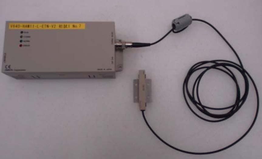
E4EV640HAM11LV2
Apr 13, 2015Carrier ID Reader/Writer (RFID)
Equipment Class
DXX - Part 15 Low Power Communication Device Transmitter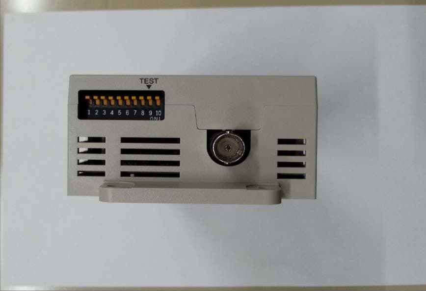
E4EV640HAM11V2
Apr 13, 2015Carrier ID Reader/Writer (RFID)
Equipment Class
DXX - Part 15 Low Power Communication Device Transmitter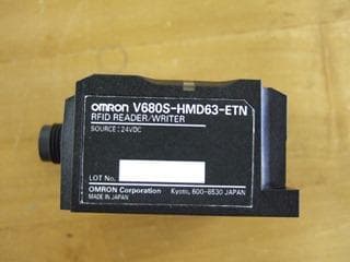
E4EV680S63
Nov 13, 2014Radio Frequency Identification System (RFID System)
Equipment Class
DXX - Part 15 Low Power Communication Device Transmitter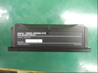
E4EV680S66
Apr 04, 2013Radio Frequency Identification System (RFID System)
Equipment Class
DXX - Part 15 Low Power Communication Device Transmitter