E9698108Transceiver
Motorola Mobility LLC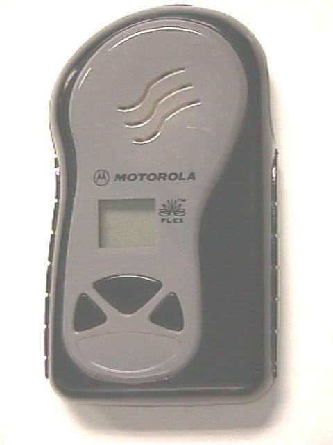
Click to zoom
Application Details
- Equipment Class
- PCT - PCS Licensed Transmitter worn on body
- Date of Grant
- Jan 05, 1999
- Application Purpose
- Original Equipment
- Date of Application
- Sep 01, 1998
- Equipment Note
- Transceiver
- Frequency Range
- 901.00000000 - 902.00000000
- Company
- Motorola Mobility LLC
- Country
- United States
Documents & Files
Document Text
Text extracted from the exhibit documents filed with the FCC. Open a document above to read the original.
Users Manual
A User’s Guide LS950v i Contents Features 1 Getting the Most from Your Voice Unit 1 Controls 2 Display Icons 3 Turning Your LS950v On 4 Using the Menu Button 4 Display 5 Turning Your Portable Answering Machine Off 5 Setting the Volume 6 Selecting an Alert Mode 6 Setting the Day and Time 7 Receiving and Listening to Your Messages 7 Receiving a Message During Playback 8 Pausing a Message 8 Message Storage 8 Selecting a Message from Memory 9 Deleting Messages From Memory 9 Locking and Unlocking Messages 10 Battery Information 11 Cleaning Your LS950v 11 Repair and Maintenance 11 Replacing the Main Battery 12 Replacing the Back-up Battery 13 WARNING The FAA has regulations concerning the use of electronic devices aboard aircraft. When boarding aircraft, turn off your LS950v to avoid potential interference with aircraft radio communication or navigation equipment. 1 Congratulations on purchasing the LS950v by Motorola. Your voice unit uses the new FLEX pager technology. With the exciting benefits your voice unit offers, it can be a vital part of your business and personal life. Features Your voice unit provides all the features of an answering machine, yet it fits in the palm of your hand. Your voice unit stores the actual voice message of the sender. Lightweight and easy to carry, your LS950v can be worn on your belt or carried in your pock et or purse. Your LS950v has many unique and easy-to-use features. You can play, r everse, fast forward, pause, lock, and delete your messages. Your messages are also stamped with the day (optional) and time your message arrived. Getting the Most from Your Voice Unit •Spend a few minutes learning all of the functions and messaging capabilities of your LS950v. •Give your LS950v number to your assistant, business associates, friends, and family. •Forward your home phone or business phone to your LS950v. •Leave your LS950v number at your children’s school and with the babysitter so you can always be reached in an emergency. 2 Controls For a description of the controls, see the Buttons subsection on page 3. Button Locations f 12 3 4 5 6 7 8 V WYIJ N C D 3 Buttons: 1Use the V button to decrease volume during playback. 2Use the W button to increase volume during playback. 3Use the Y button to turn the unit on and off. 4Use the I button to play a message, restart a paused message, and find the beginning of the next message. 5Use the J button to find the beginning of the previous message and to reverse through messages. 6Use the D button to lock and unlock messages during playback. 7Use the N button to pause during mes- sage playback, to select an alert and to set the day (optional) and time 8Use the C button to delete messages dur- ing playback. Display Icons Your voice unit displays these icons to indicate: f Volume set at maximum (level 5) i Volume set at level 2 T Audible alert mode is set to on U Vibrator mode is set to on A Unit is out of antenna range B AA Battery is low when icon is displayed b Lithium back-up battery is low when icon is displayed; battery is dead when icon is flashing L Selected message is locked 4 P A message is pending from the system’s virtual memory 4 0 Number of unplayed messages (flashing icon) or the total number of messages in memory (steady icon) Turning Your LS950v On Press and release the Y button to turn the unit on. When the unit is turned on, it responds with a 2- second audible or vibrate alert, depending on the mode. Using the Menu Button The N button performs five different functions, depending on when and how it is operated: Mode –See paragraph “Selecting an Alert Mode” on page 6. Change/Set the Time –See paragraph “Setting the Day and Time” on page 7. Change/Set the Day (optional) – See paragraph “Setting the Day and Time” on page 7. Pause –See paragraph “Pausing a Message” on page 8. Backlighting – Press and hold the menu button to activate backlighting, allowing you to read the display in a dark setting. WARNING The FAA has regulations concerning the use of electronic devices aboard aircraft. When board- ing an aircraft, turn off your voice unit to avoid potential interference with aircraft radio com- munication or navigation equipment. 5 Display • During playback, the display indicates the message number of the message being played. This message number remains displayed for 4 seconds even after fhe playback is finished. After the 4-second interval, the unit becomes idle. • When the unit is idle, the display indicates the total number of messages (played or unplayed) stored in the unit. • The display shows each message number as you sequence through the messages. • After the voice unit receives new messages, the display flashes to indicate the number of unplayed messages. • When playing a message, if the day option is enabled, the initial 2 seconds of message playback shows the time stamp, and the following 2 seconds display the day stamp. Afterwards, it displays the time stamp. Turning Your Portable Answering Machine Off Power Off–Press and hold the Y button to turn your voice unit off. A short tone or vibrate alert confirms that the power has been turned off. When your voice unit is off or out of the coverage area, new messages are stored in the system’s virtual memory. When your LS950v is turned back on and returns to the service area, the system sends you the stored messages. 6 Setting the Volume Establishing a Safe Listening Volume Level: Set the volume on your LS950v to a level that you can hear comfortably without distortion. WARNING Do not place your LS950v next to your ear and press the play ( I ) button. The volume may be set too high and may cause damage to your hearing. Hold your LS950v away from your ear to start the playback, then move the unit to a comfortable range for listening. Decreasing the Volume Level: • Press and release the V button to decrease the volume level by one step. Increasing the Volume Level: • Press and release the W button to increase the volume level by one step. Selecting an Alert…
Text truncated - open the document above for the full version.
Cover Letter(s)
FCC ID:E9698108 DATE:August 27, 1998 TO:Authorization and Evaluation Division Federal Communications Commission Laboratory 7435 Oakland Mills Road Columbia, Maryland 21045 FROM:Raju Karingattil, Staff Electrical Engineer SUBJECT:Request for Certification FCC ID: E9698108 Gentlemen: Motorola, Inc., 1500 Gateway Blvd, Boynton Beach , Fl 33436, hereby requests certification for the Boomerang transmitter Models FCC ID: E9698108 as set forth in the Federal Communication Commission's Rules and Regulations, Part 2 and 24. Model: FCC ID: E9698108 is a Frequency Modulation Communications Transceiver having three Frequency conversions and designed for the reception of one fixed frequency within the range of 929-932 MHz and 935-941 MHz, and transmitting in the range of 901 to 902 MHz. This radio equipment is intended for use in the common carrier paging system. Regards, Raju Karingattil Exhibit 1 FCC ID:E9698108
Cover Letter(s)
Motorola Inc. Paging Products Group 1500 NW. 22nd Avenue Boynton Beach, FL 33426-8292 November 11, 1998 Federal Communications Commission Authorization and Evaluation Division 7435 Oakland Mills Road Columbia, MD 21046 Attention: Mr. Frank Coperich Re: Requested Items for FCC ID: E9698108 (EA91635) [Correspondence ID: 4451] Mr. Coperich, Per your email request and our conversation last week, please find enclosed the responses to the items addressed. The ERP data (Item 1) and measurement are submitted as “ERP.doc”. Items 2 and 3 were remiss due to the fact that half of the test report was not transferred during electronic transmission. I am submitting it to the filing as “2 nd_half_test.doc”. Regarding Item 2, this particular product has already been tested by Greg Czumak at the OET labs and was found to pass the occupied BW requirements using peak readings. We are aware of the issue regarding using video averaging in occupied BW measurements and will submit peak measurements in all subsequent filings. I am waiting on the SAR data report from the RF Exposure lab that we use and expect to have it by early next week. I will forward to you as soon as I get it from them (the engineer that worked on our product has been out of the labs). Thank you very much for your assistance in this matter! Regards, William M. Elliott (Mac) Compliance Engineer (561)-739-3792 Fax (561)-739-2341 Email [email protected]
External Photos
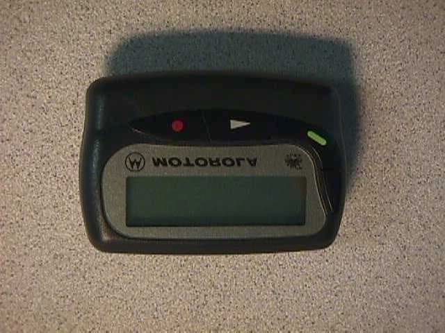
FCC ID:E9698108 Top View EXHIBIT 10A FCC ID:E9698108 Bottom View EXHIBIT 10B
ID Label/Location Info
FCC ID:E9698108 IDENTIFICATION LABEL LOCATION X See the attached photograph, Exhibit 10 TYPE X The label is a paper polyester film laminate with a pressure sensitive adhesive backing. See drawing below MARKINGS (TEXT) X See drawing below MODEL NO: XXXXXXXXXX MOTOROLA SERIAL NO: XXXXXXXXXX FCC ID: XXXXXXXXXXX EXHIBIT 2
ID Label/Location Info
FCC ID: E9698108 IDENTIFICATION LABEL LOCATION X_____ See the attached photograph, Exhibit 10 TYPE X______ The label is a paper polyester film laminate with a pressure sensitive adhesive backing. See drawing below. MARKINGS (TEXT) X_______ See drawing below ____________________________________________________ | | | MODEL NO: XXXXXXXXXX MOTOROLA | | SERIAL NO: XXXXXXXXXX | | FCC ID: E9698108 | | | | | | | |___________________________________________________ | EXHIBIT 2
Internal Photos
FCC ID:E9698108 Decoder Board Top View EXHIBIT 10C FCC ID:E9698108 Decoder Board Bottom View EXHIBIT 10D FCC ID:E9698108 Transceiver Board Top View EXHIBIT 10E FCC ID:E9698108 Transceiver Board Bottom View EXHIBIT 10F
Operational Description
FCC ID:E9698108 GENERAL INFORMATION FCC Reference Pursuant 1.Production Plans2.983 (c) Quantity production is planned. 2.Application References2.1061 Reference is made to the following Motorola "Application Reference" A. Paging and Portable Products and their application B. Portable Products Transmitter Modulation Methods C. Boynton Beach Antenna Range 3.Data Submittal Procedure Data is supplied in accordance with Part 2, Sub-part J of the Commissions rules. 4.Similar, currently Type Accepted Transmitter, FCC ID: E969681 EXHIBIT 3 FCC ID:E9698108 DESCRIPTION 1.Transmitter Technical Characteristics--Pursuant 2.983 (d) A. RF Power Out400mW EIRP B. Frequency Range Receiver929-932 & 935-941 MHz Transmitter896-902MHz C. Frequency Stability1PPM D. Emissions10KOFID E. Spurious Emissions-43dbc F. DC Voltage and Current into3.0Volts the final RF power amplifier 850 mA stage/stages Note: Following is necessary bandwidth calculation. Personal Messaging Unit Specifications: Deviation= +or -2.4 Khz maximum Note: Max modulating freq.=4800 (symbols)/2 (symbols per cycle) Max modulating frequency=2400 hertz Bn = Necessary bandwidth M= Max modulation frequency (hertz) D= Peak frequency deviation Bn = 2M + 2D = 2(2.4Khz) + 2(2.4Khz) = 9.6 Khz 2.Transmitter Application-This transmitter use is for the transmission of data only at 800, 1600, 6400 and 9600 bits per second to provide four level FSK modulation. A. Power Supplies Boomerang is powered by a 1.5 V AA battery. The transmitter is powered by a 3 volt Lithium battery internal to the unit. The receiver is supplied by a 2.8 volt regulator, 3 volt regulator and a 1 volt regulator. The controller is supplied by a 3 volt regulator. EXHIBIT 4 FCC ID:E9698108 DESCRIPTION (cont) B. Antenna Available 1. Transmit A single loop antenna is used for the transmitter . The loop antenna is housed inside the personal messaging unit and is internally connected and not user accessible. 2. Receiver The loop antenna is also used for receive and is internal to the personal messaging unit. C. Squelch Types (not applicable) D. Microphone (not applicable) E. Maximum Transmit Channel Capability The personal messaging unit is synthesized and software controlled to transmit on frequencies from 901-902 Mhz. F. Housing The transmitter is housed in the housing shown in the accompanying photos. G. Other Options (not applicable) EXHIBIT 4 (CONT)
Parts List/Tune Up Info
FCC ID:E9698108 Function of Semiconductors and other Active Devices SchematicTypeCircuit ApplicationSource Symbol Transceiver Q500NPNTransmit preamp circuitSPS Q501NPNTransmit supply switchSPS Q502PNP 3 volt switch Zetex Q503PNPTransmit switchSPS Q504PNPTransmit switchSPS Q700NPNRF AmpSPS Q701PNPRF Amp switchSPS Q702PNPB+++ switchSPS Q704PNPActive bias for 1st mixerSPS Q801PNP1 volt regulator circuitSPS Q901NPNVCO SPS Q902NPNVCO BufferSPS Q903NPNFirst injection doublerSPS Q904NPNSecond injectionSPS Q905PNP2nd VCO B+ switchSPS Q911NPNB+++ switchSPS Q912Dual NPN3 volt switchSPS Y900Resonator V1-2VCO, loop 1Transtech U601VC-TCXOReference oscillator KSS U801BICMOSLow conversion ICSPS U701MESFETFirst mixerSPS U500ICTransmit preamplifierSPS U501ICTransmit power ampRF Micro U901Regulator3 volt regulatorLiner Tech Controller Q1NPNBack up battery circuitNational Q2PNPLCDSPS Q3NPNAudio power enableSPS Q4NPNAudio dc offsetSPS Q5MOSFETBack up battery circuitNational Q6PNPAudio power enableSPS Q7PNPVibrator circuitSPS Q9NPN, Darlington Vibrator circuitSPS Q10 PNPAudio power enableSPS Q11MOSFETBack up battery circuitNational Q14MOSFETBack up battery circuitNational Q15MOSFETBack up battery circuitNational EXHIBIT 5 FCC ID:E9698108 Q16MOSFETBack up battery circuitNational Q17MOSFETBack up battery circuitNational CR4DiodeVibratorSPS CR5DiodeBack up battery circuitSPS Y1Crystal38.4 KHz ClockSeiko Function of Semiconductors and other Active Devices Schematic Device Circuit Ref. Designator Type Application Source Controller Q1NPNBack up battery circuitNational Q2PNPLCDSPS Q3NPNAudio power enableSPS Q4NPNAudio dc offsetSPS Q5MOSFETBack up battery circuitNational Q6PNPAudio power enableSPS Q7PNPVibrator circuitSPS Q10 PNPAudio power enableSPS Y1Crystal 38.4 KHz ClockSeiko U03LCD Driver LCD DriverSPS U043 volt regulator 3v power managementMaxim U05 U06Audio Amplifier Audio Amplifier NJR U07OP AMP Audio Switch Analog Device U08 Audio Amplifier Audio Power AmpNJR U10DRAM Data storage Mitsubishi U100Digital Signal Processor DSPATT U301IC Code PlugAtmel U302IC Serial ID Dallas Semi. VR100 Zener DiodeVoltage RegulatorMotorola EXHIBIT 5 (CONT) FCC ID:E9698108 TUNE UP PROCEDURE The following tune-up procedure is similar to what will appear in the final service manual enclosed. Tuning Procedure 1. All parameters are specified at room temperature of 25°C±2°C. 2. The reference oscillator is tuned with the transceiver and controller boards connected by a umbilical cable. 3. Transceiver and controller boards are properly assembled into the customer housing for transmitter tuning. Tuning back cover is used. 4. Software tuned values are stored in the code plug and the transmitter trimmer capacitor is manually tuned. The transceiver and controller must remain together from this point in the process. 5. Battery simulator has proper decoupling. 6. The power supply is set to 1.5 V DC ± 0.01 VDC. Note: For field tuning, the code plug programmer will provide the download program that is necessary to tune the DAC values into the code plug. The reference oscillator is manually tuned without the download program. Reference Oscillator 1. Set B+ to 1.5 vdc, B++ to 3.3 vdc 2. Download program from test controller to U.U.T. This includes: a. Turn off low cell and dead cell trip on controller if necessary. b. Program U801 Reg B+ 1.0 vdc on. c. Program Buff_not (TP801) low. d. Program U900 for transmit, reference to 6250 Hz and first VCO to 450 Mhz. e. Program U100 A2 output high (TP807) to turn off second LO. f. Program U801 to turn off signal path and dividers. g. Turn off U500 and U501. h. Measure frequency at TP500 using 10 pF capacitor and filter (880 to 920 Mhz) to counter. I. Reference oscillator is manually tuned to ± 0.5 PPM of 900,006,013 Hz. Note: This frequency is offset 6.68 PPM. EXHIBIT 7 FCC ID:E9698108 Tune Transmit Frequency 1. Set B+ 1.5vdc 2. Download program from test controller to U.U.T. This includes: a. U801 Reg. B+ on 1.0 vdc, signal path and dividers off. b. U100 set Buff_not low (TP801). c. U900 for transmit, first LO at 901.506328 MHz. d. U100 A2 high, second LO off. e. U801 AFC to DC nominal, Hex 128. f. U500 and U501 off. 3. Set MDA (modulation domain analyzer): a. Ext Lo +6 dBm,895 Mhz (10 MHz Ref), auto select. b. Span 5.6 Khz (700 Hz/Div) c. Find center frequency d. Time base: 100 us, Panorama off e. Sampling: Auto, Int at Center, Auto f. Averaging On/Off 4. Measure silent carrier at TP51 through 10 pf capacitor, amplifier and 880 to 920 Mhz filter to an MDA is at nominal 901.506328 MHz ± 0.5 PPM. EXHIBIT 7 (CONT) FCC ID:E9698108 Balance Tune 1. Duplicate steps 1-4 in tune transmit frequency. 2. Generate a sine wave with half level DC offset and 1.7 V p-p applied to U801 modulation DAC with low port Max DAC A at nominal dc. 3. Determine the appropriate dc offset voltage to center modulation. 4. Write the HEX value to the code plug. Low Port Modulation Tune 1. Duplicate steps 1-4 in tune transmit frequency. 2. Generate a sine wave with half level DC offset and 1.7 V p-p applied to U801 modulation DAC with low port Max DAC A at nominal dc. 3. Step dc voltage to tune level on MDA to +800 Hz. 4. Store value in the code plug. 5. Step dc voltage to tune level on MDA to -800 Hz. 6. Store value in the code plug. EXHIBIT 7 (CONT)
RF Exposure Info
FCC ID: E9698108 RF EXPOSURE INFO This unit was tested to the RF Exposure limits established by the Commission and passes all requirements. The original PRFEECT Certificate will be in the mailing containing the Form 159 for this package. A scanned copy will be attached to this filing within the next few days.
RF Exposure Info
Here are the diagrams for typical InFlexion frames 1 frame = 1 division = 1.875 seconds Summary of Protocol-compliant worst case scenarios for the Boomerang Pager Pager Scenario#ACKs/#Frames% of Frames with ACKS Registration attempt15/3444.12 WRU w/ WRU ACK½50.00 Voice msg w/ msg read ACK 3/6 50.00 This document describes the theoretical maximum inbound traffic that can be generated by a Boomerang pager. In most cases, this traffic will be less than the minimum traffic described in ReFLEX InFLEXion Protocol Specification Document Version 2.6 due to software limitations. There are three scenarios described below: 1) Maximum Inbound Traffic Caused by Registration Failures 2) Continuous stream of WRU and WRU Responses 3) Voice Message Transmission These scenarios do not reflect typical system/pager/user behavior although they are theoretically possible. Boomerang has greater limits than the protocol specifies in Section 8.5.4 Minimum Personal Decoding Requirements. The maximum message activity in a Boomerang pager is: 1 address per frame 1 pending vector (vector to ACK) 1 pending message (vector to last fragment) 8 pending fragments Boomerang is also restricted on the number of inbound responses that it can handle (see Section 8.6.6 Minimum Inbound Scheduling Requirements). Boomerang can only support: 1 pending scheduled inbound response, and 1 pending inbound (ALOHA) command Boomerang was designed to handle one transaction at a time pager, and is therefore only able to decode one vector per frame on its personal address. Any additional vectors sent in the same frame will be ignored by the pager (as described in Section 7.4.3 Error handling table). Although the pager can be directed to ACK in the same frame as received address/vector, Boomerang does not have this ability. If the system specifies a rf (response frame) of 0 in a vector, Boomerang will process the vector, but will not generate a response. The ACK will be discarded. Scenario 1: Maximum Inbound Traffic Caused by Registration Failures ------------------------------------------------------------------------------------------------------- The worst case inbound traffic scenario occurs when a pager is not registered on the system. If the system is configured so that the randomization interval is zero (ri = 0), the aloha timeout is zero (t = 0), and the number of retires is 14 (rt = 7), the pager will transmit fifteen registration requests in consecutive frames. After transmitting the 15 ACKs, the pager will move from WAIT to OUT and scan for a new channel. The time required to find the system is dependent on the pagers codeplug configuration. For a worst case scenario, the pager would be programmed with a Frame Scan Timeout of 0 (FST=0). The typical values are usually 4 or 5. A FSTO of 0 causes the pager to sleep for a minimum of 2 frames, channel activity detect for one frame, and SPID match for 1 frame. If the pager finds activity and a matching SPID on the first attempt, it will begin sending in another 15 zone registration requests. This configuration is particularly bad because the system will never be able stop the Registration Requests. In this case, the pager will transmit in one slot in 15 out of 19 frames (about 79% of frames will contain ACKs). If the FSTO of the pager is increased to a typical value, the percentage is greatly reduced. While it is possible for the system to be configured with an aloha timeout of 0, it violates the protocol. The protocol specifies that the aloha timeout must be between 1 and 255 (Section 3.7.6.21 BIW for ALOHA Time-out Period and Randomization Interval). If an aloha timeout of 1 is used, the pager will still ACK 15 times, but will wait one frame between each ACK. If the system doesn't respond after the 15th attempt, the pager will sleep for 2 frames, channel activity detect for 1 frame, and SPID match for one frame before restarting the registration requests. This results in ACKs in one slot in 15 out of 34 frames (about 44.11% of frames contain inbound traffic). Scenario 2: Continuous Stream of WRU and WRU Responses -------------------------------------------------------------------------------------------- This case could occur if the system transmits a WRU Vector to a pager in every frame with a response scheduled for the next frame. The pager will receive the vector in the first frame, but miss the WRU vector in the second frame because it is transmitting a scheduled response. This will cause the pager to ACK in every other frame (50% of frames contain inbound traffic). Boomerang is limited to one pending vector (vector to ACK), so multiple responses can not be queued up by the system. Scenario 3: Voice Message Transmission -------------------------------------------------------------- The third scenario is only possible if the system has zero turn around time for message scheduling. This means that the system needs to receive a response in one frame and act on it in time to transmit additional information in the very next frame. It is highly unlikely that any system will ever be this efficient. However, assuming an ideal system, the pager could generate the following traffic: a) WRU vector from system b) WRU response from pager (ACK) c) WTL vector from system with 1 fragment scheduled and 1 response d) Voice Fragment for WTL vector e) WTL response from pager (ACK) f) Message Read response from pager (ACK) This results in 3 inbound responses for every 6 frames (50% of frames contain inbound traffic). It is also unlikely that the user would be able to generate a Message Read response that quickly, but these are all worst case assumptions. ------------------------------------------------------------------------------ For Reference purposes: From ReFLEX InFLEXion Protocol Specification Document Version 2.6 Section 8.5.4 Minimum Personal Message Decoding Requirements A subscriber unit must support a minimum amount of messaging activity on its personal address. At any time, a subscriber uni…
Text truncated - open the document above for the full version.
RF Exposure Info
To: Dr. Kwok ChanDate: 12/28/98 From: Glenn Thompson Subject: Motorola voice pager E9698108, EAS#91635 Dr. Chan, the following information should address your concerns with the Motorola voice pager. The first concern is with the frequency range of the pager. The tunable range listed on the form 731 form is correct. The Rx operates in the 929-932 and 935-941 MHz range (929 to 942 MHz on the 731 Form), under part 24 the TX range is 901-902 MHz and under part 90, 896-901 MHz for operation in the SMR bands. In the future Motorola will test devices which qualify for source-based time-averaging at the maximum duty factors instead of using CW equivalent test signals. However, since SAR-measuring equipment is a low-pass filtering device, in conditions of very low duty-factors the source-based time-averaged measurements might be difficult to perform and the only correct approach is to use CW equivalent signals. Issues 3 through 7 are addressed by the enclosed documents from the Motorola EMI lab in Florida. [see Photos.pdf, Body_Scan.pdf, Holster_Scan.pdf, and manual.pdf] Regards, Glenn Thompson
RF Exposure Info
Thompson Glenn-EGT005 From:Tod Hufferd-ETH003 [[email protected]] Sent:Monday, January 04, 1999 3:31 PM To:Glenn Thompson-EGT005 Cc:Tod Hufferd-ETH003; Ed Clements-FEC004; Michael Piper-WLMP00 Subject:LS950V The LS950V supports one transmission per frame. This consists of a single packet transmission that have varying transmission durations depending on inbound speed. The following are the transmission durations for each of the supported inbound speeds: Inbound Data Rate Transmission Duration 800 bps160.0000 msec 1600 bps 80.0000 msec 6400 bps 24.0625 msec 9600 bps 16.0417 msec The LS950V supports two kinds of inbound transmissions. The scheduled transmission that is controlled by an address/vector combination and the ALOHA transmission that is generated by the subscriber device. To determine the inbound transmission duty cycle both the scheduled and ALOHA transmission will be considered separately. Scheduled Transmissions: The LS950V supports one transaction at a time. A transaction is defined as an address/vector/response combination. The LS950V can receive one address/vector pair in a single frame that can direct the unit to respond in the following frame. Therefore, for a schedule transmission, the LS950V can transmit every other frame. This yields the following transmit duty cycle for a given speed. Inbound Data Rate Transmission Duty Cycle 800 bps .160/3.5 = 4.57% 1600 bps .080/3.5 = 2.29% 6400 bps .024/3.5 = .69 % 9600 bps .016/3.5 = .46 % ALOHA Transmissions: The LS950V supports one active ALOHA transmission at a time. Once an ALOHA transmission has been sent by a subscriber unit, the subscriber unit must wait the ALOHA timeout before sending the ALOHA transmission again. The ALOHA timeout is configurable by the paging infrastructure. The minimum value allowed by the ReFLEX25 protocol for the ALOHA timeout parameter is 1 frame. Therefore, the subscriber device could send an ALOHA transmission in one frame, wait one frame for the response, and retry the ALOHA transmission in the following frame if no response was sent by the infrastructure. The shortest time between ALOHA transmissions would be every other frame. See the table above for the corresponding transmit duty cycle.
RF Exposure Info
The LS950V supports one transmission per frame. This consists of a single packet transmission that have varying transmission durations depending on inbound speed. The following are the transmission durations for each of the supported inbound speeds: Inbound Data Rate Transmission Duration 800 bps160.0000 msec 1600 bps 80.0000 msec 6400 bps 24.0625 msec 9600 bps 16.0417 msec The LS950V supports two kinds of inbound transmissions. The scheduled transmission that is controlled by an address/vector combination and the ALOHA transmission that is generated by the subscriber device. To determine the inbound transmission duty cycle both the scheduled and ALOHA transmission will be considered separately. Scheduled Transmissions: The LS950V supports one transaction at a time. A transaction is defined as an address/vector/response combination. The LS950V can receive one address/vector pair in a single frame that can direct the unit to respond in the following frame. Therefore, for a schedule transmission, the LS950V can transmit every other frame. This yields the following transmit duty cycle for a given speed. Inbound Data Rate Transmission Duty Cycle 800 bps .160/3.5 = 4.57% 1600 bps .080/3.5 = 2.29% 6400 bps .024/3.5 = .69 % 9600 bps .016/3.5 = .46 % ALOHA Transmissions: The LS950V supports one active ALOHA transmission at a time. Once an ALOHA transmission has been sent by a subscriber unit, the subscriber unit must wait the ALOHA timeout before sending the ALOHA transmission again. The ALOHA timeout is configurable by the paging infrastructure. The minimum value allowed by the ReFLEX25 protocol for the ALOHA timeout parameter is 1 frame. Therefore, the subscriber device could send an ALOHA transmission in one frame, wait one frame for the response, and retry the ALOHA transmission in the following frame if no response was sent by the infrastructure. The shortest time between ALOHA transmissions would be every other frame. See the table above for the corresponding transmit duty cycle.
Schematics
FCC ID:E9698108 CIRCUIT DIAGRAMS The following schematic diagrams will be similar to those that appear in the final service manual. 1.Controller/Decoder Board Schematic Revision 6 2.RF Transceiver Board Schematic Revision 6 EXHIBIT 6 FCC ID:E9698108 EXHIBIT 6A FCC ID:E9698108 EXHIBIT 6B
Test Report
FCC ID:E9698108 SUBMITTED MEASURED DATA MeasurementExhibit 1.Index9 2.RF Power Out9A 3.Modulation Characteristics a. 9600 Splatter Filter Response9B b. Baseband Filtered Data9C c. Demodulated RF Data (Deviation)9D 4.Occupied Bandwidth9E 5.Transmitter Radiated Spurious9F 6.Frequency Stability a. Tuning Range9G b. Temperature9H EXHIBIT 9 FCC ID:E9698108 FCC ID:E9698108 FCC ID:E9698108 FCC ID:E9698108 FCC ID:E9698108 FCC ID:E9698108 RADIATED SPURIOUS EMISSIONS Fc = 901.0000 MHz Frequency Level (dBc) Worst Case Polarization Fc – 10 KHz -56.8 HPol Fc 0 Fc + 10 kHz -54.4 HPol 2*Fc -44.9 HPol 3*Fc -51.2 HPol 4*Fc -55.8 HPol 5*Fc -55.9 HPol 6*Fc -71.4 HPol 7*Fc -75.4 HPol 8*Fc -71.1 Hpol 9*Fc Undetectable 10*Fc Undetectable EXHIBIT 9F Radiated Spurious Emissions -80 -70 -60 -50 -40 -30 -20 -10 0 fc-10kHzfcfc+10 kHz2*fc3*fc4*fc5*fc6*fc7*fc8*fc Frequency Level (dBc) Spur levelLimit FCC ID:E9698108 FCC ID:E9698108 FCC ID:E9698108 MEASUREMEN…
Text truncated - open the document above for the full version.
Contact Information
Applicant
Charles L Eger(Senior Director, Global Regulatory and Issue Mgmt)
Test Firm
Motorola, Inc.William Elliott
[email protected]561-739-3792
Technical Specifications
| # | Rule Parts | Frequency Range | Power Output | Emission | Tolerance |
|---|---|---|---|---|---|
| 2 | 24D | 901 MHz - 902 MHz | 360.00 mW | 10K0F1D | 1 ppm |
Other Applications from Motorola Mobility LLC
E9601110
Feb 13, 2001Motorola Scriptor Jazz 200
Equipment Class
CXX - Communications Rcvr for use w/ licensed Tx and CBs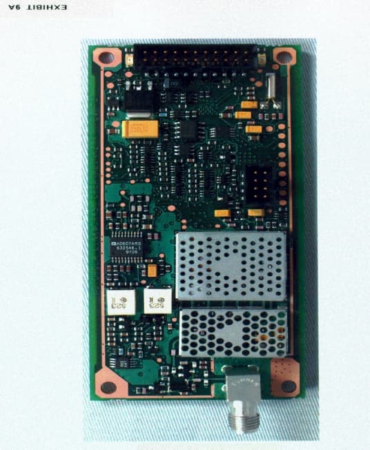
E9698109
Dec 20, 1998PCB - PCS Licensed Transmitter
Equipment Class
PCB - PCS Licensed Transmitter
E9698107
Aug 06, 1998Paging Receiver
Equipment Class
CXX - Communications Rcvr for use w/ licensed Tx and CBsE9698105
May 27, 1998Paging Receiver
Equipment Class
CXX - Communications Rcvr for use w/ licensed Tx and CBsE9698102
Mar 24, 1998CXX - Communications Rcvr for use w/ licensed Tx and CBs
Equipment Class
CXX - Communications Rcvr for use w/ licensed Tx and CBs