ED9LMX5453SMXBluetooth USB Adapter
Texas Instruments Inc.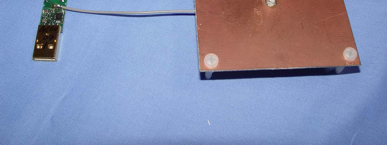
Click to zoom
Application Details
- Equipment Class
- DSS - Part 15 Spread Spectrum Transmitter
- Date of Grant
- Aug 03, 2006
- Application Purpose
- Original Equipment
- Date of Application
- Aug 03, 2006
- Equipment Note
- Bluetooth USB Adapter
- Frequency Range
- 2402.00000000 - 2480.00000000
- Company
- Texas Instruments Inc.
- Country
- United States
Documents & Files
Document Text
Text extracted from the exhibit documents filed with the FCC. Open a document above to read the original.
Cover Letter(s)
To Whom it May Concern: Part 15 Unlicensed Modular Transmitter Results 1. The modular transmitter must have its own RF shielding Shielding in integrated in the CMOS and package design. Please review the attached schematic and layout of the USB Adapter. LMX5453 Adapter Module is a fully integrated RF Transceiver, which has both baseband and RF IC in a plastic package. The entire signal chain on receiver (LNA, mixer, filters, level shifters, phase detector, equalizer), transmitter (IQ modulator, DACs, filters, mixer and PA) and synthesizer (PLL, VCO and phase detector) are integrated within LMX5453 device silicon. The RF silicon design was completed with RF shielding in the silicon design and plastic package. This complies with part 15 FCC requirements for transmission. Additionally, due to the design, it also is immune to external coupling from other circuits in a system. As a result of limited screening the LMX 5453 Adapter Module does not fully comply with #1, therefore limited modular approval applies. 2 The modular transmitter must have buffered modulation/data inputs The LMX5453 Adapter Module has buffered modulation/data inputs as shown in the datasheet. 3 The modular transmitter must have its own power supply regulation The LMX5453 Adapter Module Transmitter power supply is regulated by U3 and U4. See Schematic 4 The modular transmitter must comply with the antenna requirements of Section 15.203 and 15.204(c) All 4 antennas have been tested with the LMX5453 Adapter Module. 5 The modular transmitter must be tested in a stand- alone configuration The LMX5453 Adapter Module is tested in a standalone configuration. 6 The modular transmitter must be labeled with its own FCC ID number, and, if the FCC ID is not visible when the module is installed inside another device, then the outside of the device into which the FCC ID will be printed on top of the module when the application is approved. module is installed must also display a label referring to the enclosed module 7 The modular transmitter must comply with any specific rule or operating requirements applicable to the transmitter and the manufacturer must provide adequate instructions along with the module to explain any such requirements The LMX5453 Adapter Module datasheet and operation manual are provided with the application. 8 The modular transmitter must comply with any applicable RF exposure requirements The LMX5453 Adapter Module transmitter complies with 15.247(i) requirement. Please review the test report.
Cover Letter(s)
DATE: 06/14/06 Federal Communications Commission 7435 Oakland Mills Road Columbia, MD 21046 RE: Request for Confidential Treatment from public disclosure FCC ID: LMX5453SMX Product Name: LMX5453 USB Adapter Dear Sirs/Madam, National Semiconductor Corp. would like to request that LMX5453 USB Adapter schematics, Layout, BOM, block diagram, circuit diagram, Datasheet and User Guide submitted with the application for certification be withheld from public disclosure per Section 0.459 of the FCC Rules. This confidentiality request is made under the provisions of Section 0.457(d) of the FCC Rules and Section 552(b)(4) of the Freedom of Information Act. The various items contain proprietary, confidential and trade secret materials, which would not customarily be made available for public inspection. If you have any questions, please do not hesitate to contact me. Sincerely,
Cover Letter(s)
National Semiconductor Confidential : Page 1 of 1 Date: August 1, 2006 To whom it may concern, Due to the size and layout of the device, LMX5453 Adapter Module, regarding the label location, we couldn’t find a better place for the FCC/IC label rather than the location we have indicated in the label document. We, National Semiconductor, understand your concern, and hereby declare that we acknowledge the FCC/IC grant will be issued for LMX5453 Adapter Module, not LMX5453 Micro-module. If you have any other concerns or questions, please do not hesitate to contact us. Sincerely, Peter Zhang Klaus Knoerig Von: "Klaus Knoerig" <[email protected]> An: "Diana Eberhard" Cc: <[email protected]>; "Gordon Hurst" Gesendet: Freitag, 28. Juli 2006 15:21 Betreff: Re: National Semiconductor LMX5453 USB Adapter module Hello Diana Thank you for sending the updated material. There are still some concerns from our side: 1. User Manual The user guide describes the LMX5453 Micro-module. However, the device that is going to be certified is the USB dongle (including PCB, crystal, antenna and supporting components) as shown in the schematics. The application must clearly point this out. The user guide contains instructions on how to add crystal and antenna. This is not required for approval of the dongle. Please submit a user guide for the complete dongle, not a guide on how to assemble a dongle using the LMX5453 Micro- module. 2. Please update the Request for Modular Approval letter 2.1 Item 1 must be changed based on the FCC's interpretation, i.e. the device does not meet the definition of shielding in FCC DA 00-1407 and therefore the application is for Limited Modular Approval. 2.2 Reference should be made to the complete USB dongle in all items not just the LMX5453 Micro- module. 2.3 The RF exposure requirements are defined in 15.247(i). Please update item 8. 3. FCC and IC labelling declaration We would like to emphasize again that the FCC ID number relates to the complete USB dongle, including PCB, crystal, antenna and supporting components as specified in the submitted schematics. Attaching the label to the LMX5453 Micro-module may lead to the interpretation that only the LMX5453 chip is certified, which is not the case. When selling the LMX5453 Micro-module alone, it will not be allowed to affix the FCC ID number. Therefore we suggest to choose another label location. Best regards, Klaus Knoerig -------------------------------------------------- EMCCert DR. RASEK GmbH - Certification Institute - Boelwiese 5 91320 Ebermannstadt Germany Tel.: +49-9194-9016 Fax: +49-9194-8125 Mailto:[email protected] URL: http://www.emcc.de -------------------------------------------------- Der Inhalt dieser E-Mail ist fur den Absender rechtlich nicht verbindlich. Informieren Sie uns bitte, wenn Sie diese E-Mail faelschlicherweise erhalten haben (Fax: +49-9194-8125). Bitte loeschen Sie in diesem Falle die Nachricht. Jede Form der weiteren Benutzung ist untersagt. The content of this e-mail is not legally binding upon the sender. If this e-mail was transmitted to you by error, please inform us accordingly (Fax: +49-9194-8125). In such case you are requested to erase the message. Any use of such e-mail is strictly prohibited.
External Photos
MiCOM Labs, 3922 Valley Avenue, Suite “B”, Pleasanton, CA 94566 Tel: +1 (925) 462-0304, Fax: +1 (925) 462-0306, Web: www.micomlabs.com the wireless lab July 12, 2006 GCCO07 – A2 –Bluetooth USB Wireless Dongle National Semiconductor External Photograph Page 2 of 2 the wireless lab Dongle with external antenna
ID Label/Location Info
FCC Federal Communications Commission, To whom it may concern 15 June 2006 We, National Semiconductor Corp. DCD Group 10105 Pacific Heights Blvd. Suite 100, San Diego CA 92121 , hereby declare, That Bluetooth module LMX5453 USB Adapter’s FCC ID is ED9LMX5453SMX The FCC ID will be placed on top of the module LMX5453 as below. Example: if the module is installed inside another device, then the outside of the device into which the module is installed must displayed a label referring to the enclosed module. This exterior label can use wording such as the following: “Contains Transmitter Module LMX5453SMX FCC ID ED9LMX5453SMX” relevant information present in appropriate part of the product user manual. Yours sincerely, National Semiconductor Corp. DCD Group peter zhang
ID Label/Location Info
FCC Federal Communications Commission, To whom it may concern 15 June 2006 We, National Semiconductor Corp. DCD Group 10105 Pacific Heights Blvd. Suite 100, San Diego CA 92121 , hereby declare, That Bluetooth module LMX5453 USB Adapter’s FCC ID is ED9LMX5453SMX The FCC ID will be placed on top of the product as below. Example: if the module is installed inside another device, then the outside of the device into which the module is installed must displayed a label referring to the enclosed module. This exterior label can use wording such as the following: “Contains Transmitter Module LMX5453SMX FCC ID ED9LMX5453SMX” relevant information present in appropriate part of the product user manual. Yours sincerely, National Semiconductor Corp. DCD Group peter zhang
Internal Photos
MiCOM Labs, 3922 Valley Avenue, Suite “B”, Pleasanton, CA 94566 Tel: +1 (925) 462-0304, Fax: +1 (925) 462-0306, Web: www.micomlabs.com the wireless lab July 6, 2006 GCCO07 – A2 –Bluetooth USB Wireless Dongle National Semiconductor Internal Photograph
Test Report
COVER PAGE Test of National Semiconductor Bluetooth USB Wireless Dongle To: FCC 47 CFR Part15.247 & IC RSS-210 Test Report Serial No.: GCCO07-A2 Rev A TITLE PAGE TEST REPORT FROM Test of National Semiconductor Bluetooth USB Wireless Dongle To FCC 47 CFR Part15.247 & IC RSS-210 Test Report Serial No.: GCCO07-A2 Rev A This report supersedes: NONE Manufacturer: National Semiconductor 10105 Pacific Heights Blvd. Suite 100 San Diego California 92121 USA Product Function: Communicating Data and Audio Information Copy No:pdf Issue Date: 11th July '06 This Test Report is Issued Under the Authority of; MiCOM Labs, Inc. 3922 Valley Avenue, Suite B Pleasanton, CA 94566 USA Phone: +1 (925) 462-0304 Fax: +1 (925) 462-0306 www.micomlabs.com CERTIFICATE #2381.01 MiCOM Labs is an ISO 17025 Accredited Testing Laboratory This test report may be reproduced in full only. The document may only be updated by MiCOM Labs personnel. Any changes will be noted in the Document History section of the report. Title: To: Bluetooth USB Wireless Dongle FCC 47 CFR Part15.247 & IC RSS-210 Serial #: Issue Date: Page: GCCO07-A2 Rev A 11th July '06 3 of 93 This test report may be reproduced in full only. The document may only be updated by MiCOM This page has been left intentionally blank Labs personnel. Any changes will be noted in the Document History section of the report. MiCOM Labs, 3922 Valley Avenue, Suite B, Pleasanton, CA 94566 USA, Phone: 925.462.0304, Fax: 925.462.0306, www.micomlabs.com Title: Bluetooth USB Wireless Dongle To: Serial #: Issue Date: Page: FCC 47 CFR Part15.247 & IC RSS-210 GCCO07-A2 Rev A 11th July '06 4 of 93 This test report may be reproduced in full only. The document may only be updated by MiCOM TABLE OF CONTENTS ACCREDITATION, LISTINGS and RECOGNITION.......................................................5 1. TEST RESULT CERTIFICATE.................................................................................8 2. REFERENCES AND MEASUREMENT UNCERTAINTY........................................9 2.1. Normative References............................................................................................9 2.2. Test and Uncertainty Procedures...........................................................................9 3. PRODUCT DETAILS AND TEST CONFIGURATIONS........................................10 3.1. Technical Details..................................................................................................10 3.2. Scope of Test Program.........................................................................................11 3.3. Equipment Model(s) and Serial Number(s)..........................................................14 3.4. Antenna Details....................................................................................................14 3.5. Cabling and I/O Ports...........................................................................................14 3.6. Test Configurations...............................................................................................15 3.7. Equipment Modifications.......................................................................................15 3.8. Deviations from the Test Standard.......................................................................15 3.9. Subcontracted Testing or Third Party Data..........................................................15 4. TEST SUMMARY....................................................................................................16 5. TEST RESULTS......................................................................................................18 5.1. Device Characteristics..........................................................................................18 5.1.1. 20 dB Bandwidth.......................................................................................18 5.1.2. Channel Spacing.......................................................................................23 5.1.3. Transmitter Channels................................................................................27 5.1.4. Output Power............................................................................................36 5.1.5. Conducted Spurious Emissions................................................................41 5.1.6. Radiated Emissions..................................................................................51 5.1.7. Radiated Spurious Emissions (30M-1 GHz).............................................82 5.1.8. AC Wireline Conducted Emissions (150 kHz – 30 MHz)..........................86 6. PHOTOGRAPHS.....................................................................................................89 6.1. General Measurement Test Set-Up......................................................................89 6.2. Radiated Emissions..............................................................................................90 6.3. AC Wireline Emissions.........................................................................................91 Labs personnel. Any changes will be noted in the Document History section of the report. MiCOM Labs, 3922 Valley Avenue, Suite B, Pleasanton, CA 94566 USA, Phone: 925.462.0304, Fax: 925.462.0306, www.micomlabs.com 7. TEST EQUIPMENT DETAILS.................................................................................92 Title: Bluetooth USB Wireless Dongle To: Serial #: Issue Date: Page: FCC 47 CFR Part15.247 & IC RSS-210 GCCO07-A2 Rev A 11th July '06 5 of 93 This test report may be reproduced in full only. The document may only be updated by MiCOM ACCREDITATION, LISTINGS and RECOGNITION ACCREDITATION MiCOM Labs, Inc. an accredited laboratory complies with the international standard BS EN ISO/IEC 17025. The company is accredited by the American Association for Laboratory Accreditation (A2LA) www.a2la.org test laboratory number 2381.01. MiCOM Labs test schedule is available at the following URL; http://www.a2la.org/scopepdf/2381-01.p…
Text truncated - open the document above for the full version.
Test Setup Photos
MiCOM Labs, 3922 Valley Avenue, Suite “B”, Pleasanton, CA 94566 Tel: +1 (925) 462-0304, Fax: +1 (925) 462-0306, Web: www.micomlabs.com the wireless lab July 12, 2006 GCCO07 – A2 –Bluetooth USB Wireless Dongle National Semiconductor TEST SET-UP PHOTOGRAPHS General Measurement Test Set-Up Page 2 of 4 the wireless lab Radiated Emissions Page 3 of 4 the wireless lab Page 4 of 4 the wireless lab
Contact Information
Applicant
Ryan Lin(Marketing Engineer)
Test Firm
MiCOM LabsGordon Hurst
Technical Specifications
| # | Rule Parts | Frequency Range | Power Output |
|---|---|---|---|
| 1 | 15C | 2.40 GHz - 2.48 GHz | 1.00 mW |
Other Applications from Texas Instruments Inc.
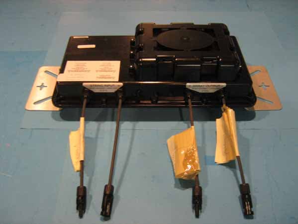
ED9SM5400
Aug 30, 2010Photovoltaic Module String Optimizer and Monitor
Equipment Class
DXX - Part 15 Low Power Communication Device Transmitter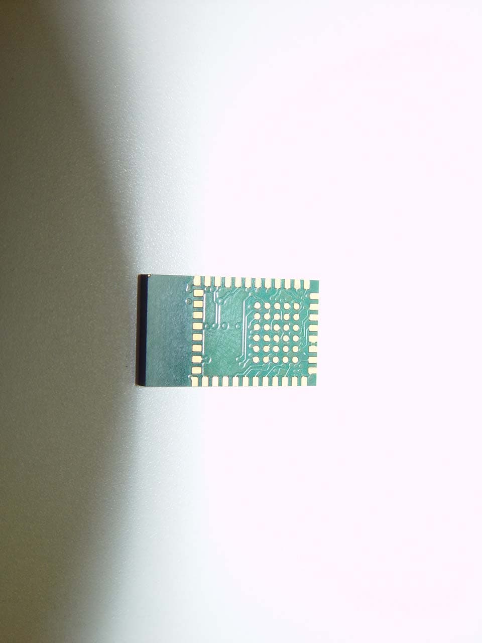
ED9LMX9838
Feb 07, 2007Bluetooth Serial Port Module
Equipment Class
DSS - Part 15 Spread Spectrum Transmitter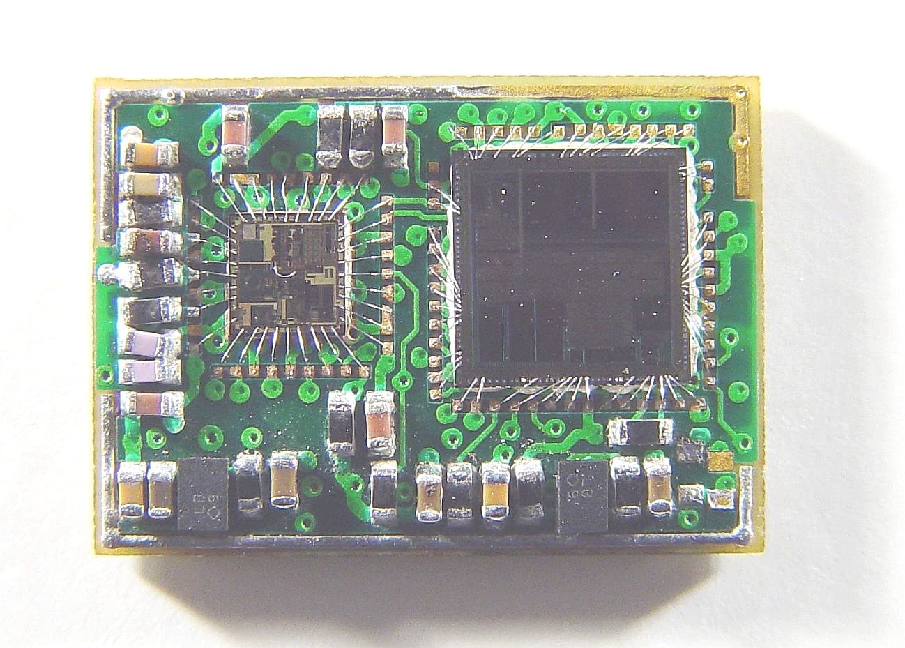
ED9LMX9820ASM
Oct 04, 2005Bluetooth Serial Port Module
Equipment Class
DSS - Part 15 Spread Spectrum Transmitter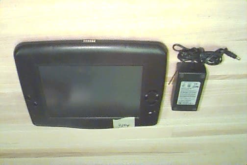
ED9GEMINIWP
Sep 10, 2000GEMINI Word Pad
Equipment Class
DSS - Part 15 Spread Spectrum Transmitter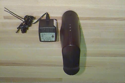
ED9GEMINIB
Aug 20, 2000Gemini Base Station
Equipment Class
DSS - Part 15 Spread Spectrum Transmitter