ED9LMX9838Bluetooth Serial Port Module
Texas Instruments Inc.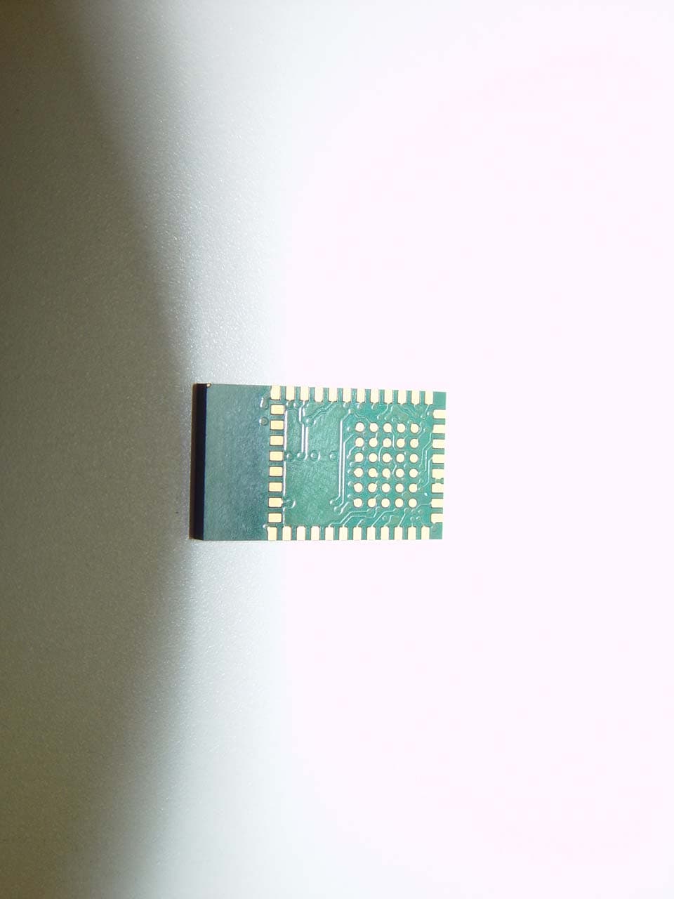
Click to zoom
Application Details
- Equipment Class
- DSS - Part 15 Spread Spectrum Transmitter
- Date of Grant
- Feb 07, 2007
- Application Purpose
- Original Equipment
- Date of Application
- Jan 31, 2007
- Equipment Note
- Bluetooth Serial Port Module
- Frequency Range
- 2402.00000000 - 2480.00000000
- Company
- Texas Instruments Inc.
- Country
- United States
Documents & Files
Document Text
Text extracted from the exhibit documents filed with the FCC. Open a document above to read the original.
Users Manual
© 2006 National Semiconductor Corporationwww.national.com LMX9838DONGLE Hardware User Guide 1.0Scope National Semiconductor LMX9838 Bluetooth ™ serial don- gle reference design kit is a plug and play serial adapter for serial cable replacement applications and more. It is able to support more profiles than just the Serial Port Profile (including audio support with external codec boards). By using the enclosed Simply Blue Commander software, it allows user to develop their own SW applications easily given the built in interpreter for HEX commands. SBSmart is a higher level application tool that provides buttons with the built in commands to easily set up or demonstrate dif- ferent profile support using the Simply Blue SPP package. 2.0General Description 2.1REFERENCE DESIGN KIT CONTENTS ■LMX9838 Bluetooth serial adapter reference board ■USB Dongle and application software stack ■Null modem cable ■Sedona Lite board (Audio CODEC Board) ■110V to 240V AC to 5V DC power adapter and pigtail ■CDROM with design documents and Simply Blue soft- ware Application tools. 2.2LMX9838 BLUETOOTH SERIAL ADAPTER REFERENCE BOARD Figure 1. Reference Board and Sedona Lite Board Bluetooth is a trademark of Bluetooth SIG, Inc. and is used under license by National Semiconductor. February 2007 Revision 0.3 LMX9838DONGLE Hardware User Guide www.national.com2 LMX9838DONGLE Hardware User Guide 3.0Qualification ■FCC certified: — FCC ID: ED9LMX9838 ■FCC compliance (see Section 13.0): The device com- plies with Part 15 of FCC Rules. Operation is subject to the following two conditions: — This device may not cause harmful interference — This device must accept any interference received, including interference that may cause undesired operation ■IC certified: — IC: 1520A-LMX9838 ■Bluetooth SIG QD ID: B012394 4.0Requirement and Setup 4.1BASIC REQUIREMENT ■X86 PC with serial port. ■One of the following operating system is required. — Windows 2000 —Windows XP 4.2APPLICATION SOFTWARE 4.2.1Simply Blue Commander Application command oriented tool to generate commands and watch events in the Simply Blue Command interface window. Reference the Simply Blue Commander User Guide document for details. 4.2.2SBSmart Easy to use Windows based tool to demonstrate additional profile support of the Simply Blue functionality. Reference the SBSmart User Guide for additional details. 4.2.3Patch Programming LMX9838 allows for patch programming for firmware update if necessary. Reference the LMX9838 SW User Guide document for details. This can also be done with the Simply Blue Commander and SBSmart tools. 5.0Functional Description 5.1POWER SUPPLY ■DC Power Jack (6V max) ■Battery Holder (6V max) 5.2MAIN SYSTEM ■Reset button for manual Reset ■Jumper option for Baud rate selection 5.3UART INTERFACE DB9 connector for RS232 standard PC interface using On- board level shifter IC for handling LMX9838 module’s 3.3V UART interface. 5.4ADVANCE AUDIO INTERFACE ■Support Audio applications ■PCM codec interface (support linear and A-law) ■PCM Master or Slave operation (SW configurable) ■Direct connection to Sedona Lite Board (A-law only) Figure 2. System Block Diagram 3www.national.com LMX9838DONGLE Hardware User Guide 6.0Design Consideration 6.1POWER MANAGEMENT ■3.3V output single LDO is used to provide power for RS232 interface chip and Digital portion of the LMX9838. 7.0Layout Consideration The LMX9838 reference design is split into 2 sections, one section is RS232 transceiver circuit for PC connection, another section is LMX9838 main circuit for Host proces- sor. (Figure 3) 7.1PCB REQUIREMENT ■2 layers PCB required ■1 mm overall thickness 7.2LAYERS CLASSIFICATION ■Top layer is the components and main signals layer ■Bottom layer is interface signals and ground plane ■RF circuit requirement ■Large ground plane with ground via’s is must for good RF performance 8.0AUDIO CODEC Board Sedona Lite Board contains an audio codec and two phone jacks. This board can be used in conjuction with LMX9838DONGLE to realize the audio (SCO) transmis- sion and reception capabilities. (See Table 9) 9.0Board components and Pin As- signments A summary of the configuration and selection jumpers is provided in the tables that follow. Reference both the sche- matic and PCB layout (included on the CD in the kit) Table 1 Major Components List DeviceDescription U1 National LMX9838 Serial Port Module - Refer- ence the device datasheet. U3 National LP3985 Low-Dropout Voltage Regula- tor U2 Maxim MAX3225 1 Mbps High Speed UART Driver Table 2 Connectors Summary ConnectorDescriptionDetails J7Battery Connector 2mm pitch Maximum input volt- age is 6V J6DC jackSame as above J8DP9 serial connec- tor (male) See Table 5 J5External processor interface See Table 6 J4Advance Audio interface See Table 7 Table 3 Jumper and Test Point Summary Jumper / Test Point DescriptionDetails J1, J2 and J3 Clock & UART set- ting jumper See Table 8 Table 4 Switch and LEDs Switch/LEDDescription S1Reset button D1Operation Status D2Data Traffic (TX/RX) Table 5 J8 DP9 (male) Pin Assignments Pin #Signal nameDescription 1NCNo connection 2RxDReceive Data (input) 3TxDTransmit Data (output) 4NCNo connection 5GNDGround 6NCNo connection 7RTSReady to send (output) 8CTSClear to send (input) 9NCNo connection www.national.com4 LMX9838DONGLE Hardware User Guide Table 6 J5 External Processor Interface Pin # Signal nameDescription 1POWER_D#ON/OFF control of LMX9838 2VCCLDO output (3.3V) 3GNDGround 4TXDTransmit Data (output) 5CTS#Clear to send (input) 6RXDReceive Data (input) 7RTS#Ready to send (output) 8VCC_CORE _IN 1.8V voltage regulator input/out- put 9RESET#Reset (input) Table 7 J4 Advance Audio Interface Pin # Signal nameDescription 1VCC LDO output (3.3V) 2SCLK Advanced Audio Interface Clock 3STD Advanced Audio Interface Transmit Data 4SFS Advanced Audio Interface Frame Synchronization 5SRD Advanced Audio Interface Receive Data 6GND Ground Table 8 UART interface setting J2J3J1UART baud rate ShortShortShort921600bps ShortOpenSho…
Text truncated - open the document above for the full version.
Cover Letter(s)
National Semiconductor Corp. FCC ID: ED9LMX9838 Request for transmitter modular approval Transmitter Module Characteristics Item Requirements EUT 1 Have its own RF shielding The device is a fully integrated antenna, crystal, RF Transceiver, which has both baseband and RF IC in a encapsulated package. The entire signal chain on receiver (LNA, mixer, filters, level shifters, phase detector, equalizer), transmitter (IQ modulator, DACs, filters, mixer and PA) and synthesizer (PLL, VCO and phase detector) are integrated within the device silicon. The RF silicon design was completed with RF shielding in the silicon design and plastic package. This complies with part 15 FCC requirements for transmission. Additionally, due to the design, it also is immune to external coupling from other circuits in a system. As a result, this device complies with #1 modular transmitter requirements with RF shielding. 2 Have buffered modulation/data inputs (if such inputs are provided), The module has a memory management unit inside of the IC. It buffers the data inputs from the UART terminal. 3 Have it own power supply regulation Internal 2.8V regulator for radio and 1.8V regulator embedded in baseband. 4 Meet the antenna requirements of Section 15.203 Internal antenna 5 Be tested in a stand-alone configuration, i.e., the antenna, AC or DC power and data input/output lines must be connected to the module but, the module must not be inside another case during testing The EUT was tested in a stand-alone configuration. The module was fixed in Development Kit during the test. 6 Be labeled with its own FCC ID number, and if the FCC ID is not visible when the module is installed inside another device , The proposed FCC ID label format will be included in the filing. When the module is installed inside of an end- product, OEM customer will be then the outside of the device into which the module is installed must also display a label referring to the enclosed module. instructed to how to apply the exterior label. Relevant OEM labelling requirements present in the product user manual. 7 The modular transmitter is manufactured so that the user cannot influence the operation of the transmitter that will operate outside of the scope of the regulations. The device is a fully integrated antenna, crystal, RF Transceiver, which has both baseband and RF IC in a encapsulated package. The entire signal chain on receiver (LNA, mixer, filters, level shifters, phase detector, equalizer), transmitter (IQ modulator, DACs, filters, mixer and PA) and synthesizer (PLL, VCO and phase detector) are integrated within the device silicon. 8 Address compliance with the Commission's RF exposure limits in Sections 1.1310 and 2.1093. In addition, spread spectrum transmitters operating under Section 15.247 are required to address RF exposure compliance in accordance with Section 15.247(b)(4). Highest RF conducted output power and EIRP are below the SAR low power threshhold, SAR testing is not applicable
Cover Letter(s)
1 Helen Zhao From: September Radecki Sent: Thursday, February 08, 2007 10:57 AM To: Helen Zhao Cc: Kathy Yao Subject: RE: National Semiconductor Corporation, FCC ID: ED9LMX9838, Assessment NO.: AN07T6485, Notice#1 FCC label.pdfExternal Photos.pdfInternal Photos.pdfBlock of diagram revised.pdf Thoery of peration Revised.pd 06U10658-1B FCC BLUETOOTH REP... User Manual Revised.pdf Antenna pecification Revised. Hi Helen, Here are the answers to your questions: Question #1: The proposed FCC ID label format shows FCC ID: ED9LMX9838SB, which does not agree with Form 731 or test report. Also FCC DoC logo was used to replace "FCC ID", which is incorrect. Please update the FCC ID label format. Answer: Please see attached revised Label. Question #2: The external photo exhibit contains one photo only, it only shows top view of the product. Please provide the bottom view. Answer: Please see revised external photos, attached. Question #3: Please provide more internal photo(s) to show close view of the component side. The internal photo exhibit includes a PCB board with two connectors, please explain what it is, is it part of the EUT? Answer: Please see attached revised internal photos as well as revised Theory of Operations and Block Diagram. Question #4: The test report indicates the antenna gain is -2dBi, however the antenna spec shows peak antenna gain: 2dBi, please confirm which is correct. You may need to update MPE calculation in the test report. Answer: This was a typo in the PIS that carried to the test report. The antenna specification has been verified as correct, and the report has been updated, including MPE. (Please see attached report.)A new Antenna Specification is also attached. Question #5: The User manual does not contain any regulatory statements. Please add user information as specified in FCC15.19(c) and FCC 15.21, and RF exposure statement specified in FCC15. 247. Since this is a modular approval application, please include instructions the OEM installers as how to label the final product, and how to meet RF exposurement. Answer: Please see attached revised User Manual. Kindest regards, September -----Original Message----- 2 From: Helen Zhao Sent: Thursday, February 01, 2007 1:09 PM To: September Radecki Cc: Barbara Judge; Michael Heckrotte Subject: FW: National Semiconductor Corporation, FCC ID: ED9LMX9838, Assessment NO.: AN07T6485, Notice#1 Hello September, I have reviewed this application, below are my comments. Thank you, Helen -----Original Message----- From: Helen Zhao Sent: Thursday, February 01, 2007 1:07 PM To: Helen Zhao Subject: National Semiconductor Corporation, FCC ID: ED9LMX9838, Assessment NO.: AN07T6485, Notice#1 Question #1: The proposed FCC ID label format shows FCC ID: ED9LMX9838SB, which does not agree with Form 731 or test report. Also FCC DoC logo was used to replace "FCC ID", which is incorrect. Please update the FCC ID label format. Question #2: The external photo exhibit contains one photo only, it only shows top view of the product. Please provide the bottom view. Question #3: Please provide more internal photo(s) to show close view of the component side. The internal photo exhibit includes a PCB board with two connectors, please explain what it is, is it part of the EUT? Question #4: The test report indicates the antenna gain is -2dBi, however the antenna spec shows peak antenna gain: 2dBi, please confirm which is correct. You may need to update MPE calculation in the test report. Question #5: The User manual does not contain any regulatory statements. Please add user information as specified in FCC15.19(c) and FCC 15.21, and RF exposure statement specified in FCC15. 247. Since this is modular approval application, please include instructions the OEM installers as how to label the final product, and how to meet RF exposurement. Attached is an example for your reference only. Best Regards, Helen Zhao The items indicated above must be submitted before processing can continue on the above referenced application. Failure to provide the requested information within 30 days of the original e-mail date may result in application dismissal and forfeiture of the filing fee. Also, please note that partial responses increase processing time and should not be submitted. Any questions about the content of this correspondence should be directed to the e-mail address listed below the name of the sender. 3
ID Label/Location Info
FCC-IC Label Format Applicant : National Semiconductor Corp. • 2VT63ES LMX9838SB FCC ID: ED9LMX9838 QD ID: B012038 IC:1520A-LMX9838 2VT63ES LMX9838SB FCC ID: ED9LMX9838 QD ID: B012038 IC:1520A-LMX9838
Test Report
FCC CFR47 PART 15 SUBPART C CERTIFICATION TEST REPORT FOR BLUETOOTH SERIAL PORT MODULE MODEL NUMBER: LMX9838SB FCC ID: ED9LMX9838 REPORT NUMBER: 06U10658-1, REVISION B ISSUE DATE: FEBRUARY 8, 2007 Prepared for NATIONAL SEMICONDUCTOR 10105 PACIFIC HEIGHTS BLVD, SUITE 100 SAN DIEGO, CA 92121 USA Prepared by COMPLIANCE CERTIFICATION SERVICES 47173 BENICIA STREET FREMONT, CA 94538, USA TEL: (510) 771-1000 FAX: (510) 661-0888 REPORT NO: 06U10658-1B DATE: FEBRUARY 8, 2007 EUT: BLUETOOTH SERIAL PORT MODULE FCC ID: ED9LMX9838 Page 2 of 72 COMPLIANCE CERTIFICATION SERVICES DOCUMENT NO: CCSUP4031A 47173 BENICIA STREET, FREMONT, CA 94538, USA TEL: (510) 771-1000 FAX: (510) 661-0888 This report shall not be reproduced except in full, without the written approval of CCS. Revision History Rev. Issue Date Revisions Revised By -- 01/26/07 Initial Issue T.C. B 02/08/07 Corrected typo in antenna gain info. T.C. REPORT NO: 06U10658-1B DATE: FEBRUARY 8, 2007 EUT: BLUETOOTH SERIAL PORT MODULE FCC ID: ED9LMX9838 Page 3 of 72 COMPLIANCE CERTIFICATION SERVICES DOCUMENT NO: CCSUP4031A 47173 BENICIA STREET, FREMONT, CA 94538, USA TEL: (510) 771-1000 FAX: (510) 661-0888 This report shall not be reproduced except in full, without the written approval of CCS. TABLE OF CONTENTS 1. ATTESTATION OF TEST RESULTS............................................................................................. 4 2. TEST METHODOLOGY .................................................................................................................. 5 3. FACILITIES AND ACCREDITATION .......................................................................................... 5 4. CALIBRATION AND UNCERTAINTY.......................................................................................... 5 4.1. MEASURING INSTRUMENT CALIBRATION ............................................................................. 5 4.2. MEASUREMENT UNCERTAINTY ............................................................................................... 5 5. EQUIPMENT UNDER TEST............................................................................................................6 5.1. DESCRIPTION OF EUT ..............................................................................................................6 5.2. MAXIMUM OUTPUT POWER .................................................................................................... 6 5.3. DESCRIPTION OF AVAILABLE ANTENNAS ............................................................................. 7 5.4. SOFTWARE AND FIRMWARE .................................................................................................... 7 5.5. WORST-CASE CONFIGURATION AND MODE......................................................................... 7 5.6. DESCRIPTION OF TEST SETUP ................................................................................................ 7 6. TEST AND MEASUREMENT EQUIPMENT ................................................................................ 9 7. LIMITS AND RESULTS ................................................................................................................. 10 7.1. ANTENNA PORT CHANNEL TESTS ......................................................................................... 10 7.1.1. 20 dB BANDWIDTH ......................................................................................................... 10 7.1.2. HOPPING FREQUENCY SEPARATION......................................................................... 14 7.1.3. NUMBER OF HOPPING CHANNELS ............................................................................. 16 7.1.4. AVERAGE TIME OF OCCUPANCY ............................................................................... 21 7.1.5. PEAK OUTPUT POWER .................................................................................................. 23 7.1.6. MAXIMUM PERMISSIBLE EXPOSURE ........................................................................ 27 7.1.7. AVERAGE POWER........................................................................................................... 30 7.1.8. PEAK POWER SPECTRAL DENSITY ............................................................................ 31 7.1.9. CONDUCTED SPURIOUS EMISSIONS.......................................................................... 35 7.2. RADIATED EMISSIONS.............................................................................................................44 7.2.1. TRANSMITTER RADIATED SPURIOUS EMISSIONS ................................................. 44 7.2.2. TRANSMITTER RADIATED EMISSIONS ABOVE 1 GHZ .......................................... 47 7.2.3. WORST-CASE RADIATED EMISSIONS BELOW 1 GHz ............................................. 56 7.3. POWERLINE CONDUCTED EMISSIONS ................................................................................ 57 8. SETUP PHOTOS .............................................................................................................................. 64 REPORT NO: 06U10658-1B DATE: FEBRUARY 8, 2007 EUT: BLUETOOTH SERIAL PORT MODULE FCC ID: ED9LMX9838 Page 4 of 72 COMPLIANCE CERTIFICATION SERVICES DOCUMENT NO: CCSUP4031A 47173 BENICIA STREET, FREMONT, CA 94538, USA TEL: (510) 771-1000 FAX: (510) 661-0888 This report shall not be reproduced except in full, without the written approval of CCS. 1. ATTESTATION OF TEST RESULTS COMPANY NAME: NATIONAL SEMICONDUCTOR 10105 PACIFIC HEIGHTS BLVD, SUITE 100 SAN DIEGO, CA 92121 USA EUT DESCRIPTION: BLUETOOTH SERIAL PORT MODULE MODEL: LMX9838SB SERIAL NUMBER: 13, 14 DATE TESTED: OCTOBER 23-26, 2006 APPLICABLE STANDARDS STANDARD TEST RESULTS FCC PART 15 SUBPART C NO NON-COMPLIANCE NOTED Compliance Certification Services, Inc. tested the above equipment in accordance with the requirements set forth in the above standards. The test results show that the equipment tested is capable of demonstrating compliance with the requirements as docume…
Text truncated - open the document above for the full version.
Test Setup Photos
REPORT NO: 06U10658-1 DATE: JANUARY 26, 2007 EUT: BLUETOOTH SERIAL PORT MODULE FCC ID: ED9LMX9838 Page 64 of 72 COMPLIANCE CERTIFICATION SERVICES DOCUMENT NO: CCSUP4031A 47173 BENICIA STREET, FREMONT, CA 94538, USA TEL: (510) 771-1000 FAX: (510) 661-0888 This report shall not be reproduced except in full, without the written approval of CCS. 8. SETUP PHOTOS ANTENNA PORT CONDUCTED RF MEASUREMENT SETUP ANTENNA PORT CONDUCTED PHOTO REPORT NO: 06U10658-1 DATE: JANUARY 26, 2007 EUT: BLUETOOTH SERIAL PORT MODULE FCC ID: ED9LMX9838 Page 65 of 72 COMPLIANCE CERTIFICATION SERVICES DOCUMENT NO: CCSUP4031A 47173 BENICIA STREET, FREMONT, CA 94538, USA TEL: (510) 771-1000 FAX: (510) 661-0888 This report shall not be reproduced except in full, without the written approval of CCS. RADIATED RF MEASUREMENT SETUP RADIATED X Position Front REPORT NO: 06U10658-1 DATE: JANUARY 26, 2007 EUT: BLUETOOTH SERIAL PORT MODULE FCC ID: ED9LMX9838 Page 66 of 72 COMPLIANCE CERTIFICATION SERVICES DOCUMENT NO: CCSUP4031A 47173 BENICIA STREET, FREMONT, CA 94538, USA TEL: (510) 771-1000 FAX: (510) 661-0888 This report shall not be reproduced except in full, without the written approval of CCS. RADIATED X Position back REPORT NO: 06U10658-1 DATE: JANUARY 26, 2007 EUT: BLUETOOTH SERIAL PORT MODULE FCC ID: ED9LMX9838 Page 67 of 72 COMPLIANCE CERTIFICATION SERVICES DOCUMENT NO: CCSUP4031A 47173 BENICIA STREET, FREMONT, CA 94538, USA TEL: (510) 771-1000 FAX: (510) 661-0888 This report shall not be reproduced except in full, without the written approval of CCS. Y-AXIS PHOTO REPORT NO: 06U10658-1 DATE: JANUARY 26, 2007 EUT: BLUETOOTH SERIAL PORT MODULE FCC ID: ED9LMX9838 Page 68 of 72 COMPLIANCE CERTIFICATION SERVICES DOCUMENT NO: CCSUP4031A 47173 BENICIA STREET, FREMONT, CA 94538, USA TEL: (510) 771-1000 FAX: (510) 661-0888 This report shall not be reproduced except in full, without the written approval of CCS. Z-AXIS PHOTO REPORT NO: 06U10658-1 DATE: JANUARY 26, 2007 EUT: BLUETOOTH SERIAL PORT MODULE FCC ID: ED9LMX9838 Page 69 of 72 COMPLIANCE CERTIFICATION SERVICES DOCUMENT NO: CCSUP4031A 47173 BENICIA STREET, FREMONT, CA 94538, USA TEL: (510) 771-1000 FAX: (510) 661-0888 This report shall not be reproduced except in full, without the written approval of CCS. POWERLINE CONDUCTED EMISSIONS MEASUREMENT SETUP EUT LINE CONDUCTED FRONT PHOTO REPORT NO: 06U10658-1 DATE: JANUARY 26, 2007 EUT: BLUETOOTH SERIAL PORT MODULE FCC ID: ED9LMX9838 Page 70 of 72 COMPLIANCE CERTIFICATION SERVICES DOCUMENT NO: CCSUP4031A 47173 BENICIA STREET, FREMONT, CA 94538, USA TEL: (510) 771-1000 FAX: (510) 661-0888 This report shall not be reproduced except in full, without the written approval of CCS. EUT LINE CONDUCTED BACK PHOTO REPORT NO: 06U10658-1 DATE: JANUARY 26, 2007 EUT: BLUETOOTH SERIAL PORT MODULE FCC ID: ED9LMX9838 Page 71 of 72 COMPLIANCE CERTIFICATION SERVICES DOCUMENT NO: CCSUP4031A 47173 BENICIA STREET, FREMONT, CA 94538, USA TEL: (510) 771-1000 FAX: (510) 661-0888 This report shall not be reproduced except in full, without the written approval of CCS. POWERLINE CONDUCTED EMISSIONS MEASUREMENT SETUP(SUPPORT LAPTOP) LINE CONDUCTED FRONT PHOTO REPORT NO: 06U10658-1 DATE: JANUARY 26, 2007 EUT: BLUETOOTH SERIAL PORT MODULE FCC ID: ED9LMX9838 Page 72 of 72 COMPLIANCE CERTIFICATION SERVICES DOCUMENT NO: CCSUP4031A 47173 BENICIA STREET, FREMONT, CA 94538, USA TEL: (510) 771-1000 FAX: (510) 661-0888 This report shall not be reproduced except in full, without the written approval of CCS. END OF REPORT LINE CONDUCTED BACK PHOTO Test Board 1 EUT Test Boards 2 EUT
Contact Information
Applicant
Ryan Lin(Marketing Engineer)
Test Firm
Compliance Certification ServicesBarbara Judge
Technical Specifications
| # | Rule Parts | Frequency Range | Power Output |
|---|---|---|---|
| 1 | 15C | 2.40 GHz - 2.48 GHz | 1.63 mW |
Other Applications from Texas Instruments Inc.
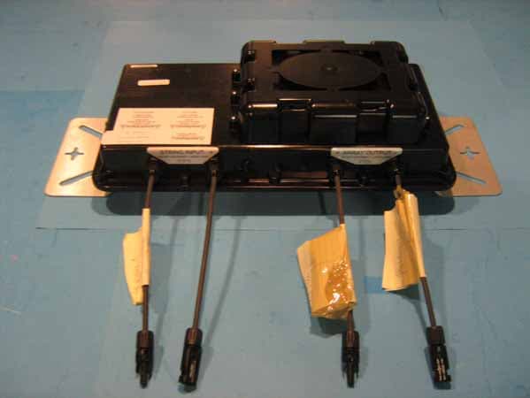
ED9SM5400
Aug 30, 2010Photovoltaic Module String Optimizer and Monitor
Equipment Class
DXX - Part 15 Low Power Communication Device Transmitter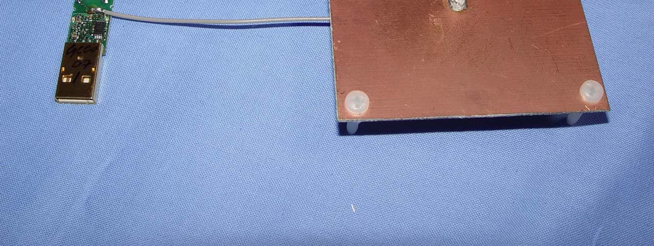
ED9LMX5453SMX
Aug 03, 2006Bluetooth USB Adapter
Equipment Class
DSS - Part 15 Spread Spectrum Transmitter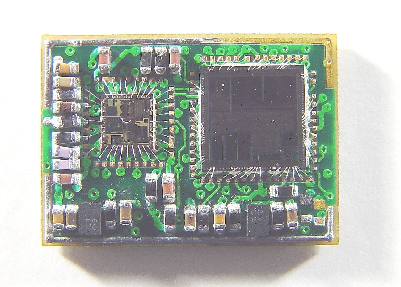
ED9LMX9820ASM
Oct 04, 2005Bluetooth Serial Port Module
Equipment Class
DSS - Part 15 Spread Spectrum Transmitter
ED9GEMINIWP
Sep 10, 2000GEMINI Word Pad
Equipment Class
DSS - Part 15 Spread Spectrum Transmitter
ED9GEMINIB
Aug 20, 2000Gemini Base Station
Equipment Class
DSS - Part 15 Spread Spectrum Transmitter