EF9MRS-1200T48UImage Scanner
Microtek International Inc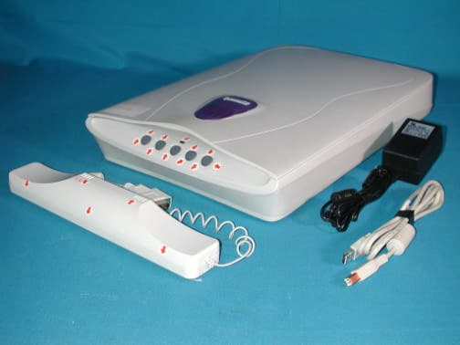
Click to zoom
Application Details
- Equipment Class
- JBP - Part 15 Class B Computing Device Peripheral
- Date of Grant
- Jul 12, 2001
- Application Purpose
- Original Equipment
- Date of Application
- Jul 12, 2001
- Equipment Note
- Image Scanner
- Company
- Microtek International Inc
- Country
- Taiwan
Documents & Files
Document Text
Text extracted from the exhibit documents filed with the FCC. Open a document above to read the original.
Users Manual
12 3 45 D ocum entation PCMAC Unpack the scanner and check components Unpack the scanner package and check for major components. Please refer to the enclosed Packing List for a detailed listing of your components. Microtek Scanner Power Adapter USB (Universal Serial Bus) Cable Documentation Microtek CD-ROM Install the software PC: A.Place the Microtek CD-ROM into the CD-ROM drive. B.Follow the on-screen instructions to install the driver and software. Do not turn off your computer until all the software has been installed. NOTE: If the Microtek Software Installer screen does not come up automatically, double-click the following in succession: My Computer on your Windows desktop; the CD-ROM icon; then cdsetup.exe to start the installer program. C.Install the image-editing software application that came with your scanner. D.Restart your computer. Unlock the scanner carriage With the scanner power off, locate the carriage safety lock at the underside of the scanner (front-right corner). Slide the lever slightly to the right until you hear a "click," indicating that the scanner carriage has been unlocked. Connect the USB cable A.Connect the computer end of the USB cable to your computer. B.Connect the other end of the USB cable to the USB port of the scanner. The system will detect your scanner automatically. Connect the power adapter to a power source A.Connect the power adapter to the back of the scanner. B.Plug the power adapter into a wall outlet or other power source. The green LED on the scanners front panel will light up. MAC: A.Install the image-editing software application that came with your scanner. B.Place the Microtek CD-ROM into the CD-ROM drive and install all the software components. C.Restart your computer. Unlock Visit us at www.microtek.com Microtek International, Inc. I49-003095 A B A PC MAC B A Déverrouiller le chariot du scanner Eteignez le scanner et repérez le verrou de sécurité sous le scanner (coin droit avant). Tirez le levier vers la droite, jusquà ce que vous entendez un « clic » indiquant que le chariot du scanner est débloqué. Connecter le câble USB A.Connectez une extrémité du câble USB à votre ordinateur . B.Connectez lautre extrémité du câble USB au port USB du scanner. Le système détectera automatiquement votre scanner. Connectez ladaptateur dalimentation à une source dalimentation A.Connectez ladaptateur dalimentation au dos du scanner. B.Branchez ladaptateur dalimentation dans une prise murale ou une autre source dalimentation. Le voyant vert sur le panneau avant du scanner sallume. Destrave o carro do scanner Com o scanner desligado, localize a trava de segurança do carro no lado inferior do scanner (no canto frontal direito). Deslize a alavanca suavemente para a direita até ouvir um "clique", o que indica que o carro do scanner foi destravado. Conecte o cabo USB A.Conecte a extremidade do cabo USB do computador no computador. B.Conecte a outra extremidade do cabo USB na porta USB do scanner. O sistema detectará automaticamente o scanner. Conecte o adaptador a uma fonte de alimentação A.Conecte o adaptador de energia na parte traseira do scanner. B.Conecte o adaptador em uma tomada de parede ou em outra fonte de alimentação. O LED verde, no painel frontal do scanner, acenderá. Desbloquee el carro del escáner Con el escáner desconectado, localice el cierre de seguridad del cartucho en la parte inferior del escáner (esquina frontal derecha). Deslice la palanca ligeramente hacia la derecha hasta que oiga un clic que indica que se ha desbloqueado el carro del escáner. Conecte el cable USB A.Conecte al sistema el extremo del cable USB del sistema. B.Conecte el otro extremo del cable al puerto USB del escáner. El sistema detectará automáticamente el escáner. Conecte el adaptador de alimentación a una toma de corriente A.Conecte el adaptador de alimentación a la parte posterior del escáner. B.Conecte el adaptador de alimentación a una toma de corriente u otra conexión eléctrica. Se encenderá el indicador luminoso verde situado en la parte frontal del escáner. Desembale el escáner y compruebe los componentes Desembale el escáner y compruebe si se incluyen todos los componentes. En la lista de componentes encontrará información detallada sobre los componentes incluidos. Escáner Microtek Adaptador de alimentación Cable USB (Bus Serie Universal) Documentación CD-ROM Microtek Instale el software PC: A.Inserte el CD-ROM Microtek en la unidad de CD-ROM. B.Siga las instrucciones de la pantalla para instalar el controlador y el software. No apague su PC hasta que se hayan instalado todos los programas. Nota: Si no aparece automáticamente la pantalla de instalación del escáner, haga doble clic en estos elementos: Mi PC, en el escritorio de Windows; el icono del CD- ROM y finalmente en el programa cdsetup.exe para iniciar el programa de instalación. C.Instale la aplicación de edición de imágenes que se entrega con el escáner. D.Reinicie el sistema. MAC: A.Instale la aplicación de edición de imágenes que se entrega con el escáner. B.Inserte el CD-ROM Microtek en la unidad de CD-ROM e instale todos los programas. C.Reinicie el equipo. Déballer le scanner et contrôler les composants Déballez le scanner et contrôlez les composants. La liste incluse détaille tous les articles dans la boîte. Scanner Microtek Adaptateur dalimentation Câble USB (Universal Serial Bus) Documentation CD-ROM Microtek Desembale o scanner e verifique os componentes Abra o pacote do scanner e verifique os principais componentes. Por favor, consulte a Lista dos Itens Embalados, que veio incluída, para obter uma relação detalhada dos seus componentes. Scanner Microtek Adaptador de Energia Cabo USB (Universal Serial Bus Barramento Serial Universal) Documentação CD-ROM Microtek Installer les logiciels PC: A.Placez le CD-ROM Microtek dans votre lecteur CD-ROM. B.Suivez les instructions sur lécran pour installer le gestionnaire …
Text truncated - open the document above for the full version.
External Photos
Report No: 015H056FI Page: 1 of 3 Version: 1.0 Attachment 2 : EUT Detailed Photographs M/N: MRS-1200T48U (Adapter: High Power, HPW-1512A) (1) EUT Photo (2) EUT Photo Report No: 015H056FI Page: 2 of 3 Version: 1.0 M/N: MRS-1200T48U (Adapter: Li Shin, LSE9801B12 (USA) (3) EUT Photo (4) EUT Photo Report No: 015H056FI Page: 3 of 3 Version: 1.0 M/N: MRS-1200T48U (Adapter: DVE, DSA-0151A-12S) (5) EUT Photo (6) EUT Photo
ID Label/Location Info
MICROTEK FCC ID.: EF9MRS-1200T48U No. 6 Industry East Road 3, Science-Based Industrial Park, Hsinchu, Taiwan, R.O.C. Tel: 886 3 5772155#213 Fax: 886 3 564-3647 FCC ID Label Sample Image Scanner Model No.: MRS-1200T48U F F C C C C I I D D : : E E F F 9 9 M M R R S S - - 1 1 2 2 0 0 0 0 T T 4 4 8 8 U U This device complies with Part 15 of the FCC Rules. Operation is subject to the following two conditions: (1) this device may not cause harmful interference and (2) this device must accept any interference received, including interference that may cause undesired operation. S/N: Made in Taiwan
ID Label/Location Info
MICROTEK FCC ID.: EF9MRS-1200T48U No. 6 Industry East Road 3, Science-Based Industrial Park, Hsinchu, Taiwan, R.O.C. Tel: 886 3 5772155#213 Fax: 886 3 564-3647 LabelLoc The FCC ID Label will be placed on the equipment as shown in the photograph below.
Internal Photos
Report No: 015H056FI Page: 1 of 22 Version: 1.0 Attachment 2 : EUT Detailed Photographs (1) EUT Photo (2) EUT Photo Report No: 015H056FI Page: 2 of 22 Version: 1.0 Report No: 015H056FI Page: 3 of 22 Version: 1.0 (3) EUT Photo (4) EUT Photo Report No: 015H056FI Page: 4 of 22 Version: 1.0 (5) EUT Photo (6) EUT Photo Report No: 015H056FI Page: 5 of 22 Version: 1.0 (7) EUT Photo (8) EUT Photo Report No: 015H056FI Page: 6 of 22 Version: 1.0 (9) EUT Photo (10) EUT Photo Report No: 015H056FI Page: 7 of 22 Version: 1.0 (11) EUT Photo (12) EUT Photo Report No: 015H056FI Page: 8 of 22 Version: 1.0 (13) EUT Photo (14) EUT Photo Report No: 015H056FI Page: 9 of 22 Version: 1.0 (15) EUT Photo (16) EUT Photo Report No: 015H056FI Page: 10 of 22 Version: 1.0 (17) EUT Photo (18) EUT Photo Report No: 015H056FI Page: 11 of 22 Version: 1.0 (19) EUT Photo Report No: 015H056FI Page: 12 of 22 Version: 1.0 (20) EUT Photo Report No: 015H056FI Page: 13 of 22 Version: 1.0 (21) EUT Photo Report No: 015H056FI Page: 14 of 22 Version: 1.0 Adapter: High Power, HPW-1512A (22) EUT Photo (23) EUT Photo Report No: 015H056FI Page: 15 of 22 Version: 1.0 (24) EUT Photo Report No: 015H056FI Page: 16 of 22 Version: 1.0 (25) EUT Photo (26) EUT Photo Report No: 015H056FI Page: 17 of 22 Version: 1.0 Adapter: Li Shin, LSE9801B12 (USA) (27) EUT Photo (28) EUT Photo Report No: 015H056FI Page: 18 of 22 Version: 1.0 (29) EUT Photo Report No: 015H056FI Page: 19 of 22 Version: 1.0 (30) EUT Photo (31) EUT Photo Report No: 015H056FI Page: 20 of 22 Version: 1.0 Adapter: DVE, DSA-0151A-12S (32) EUT Photo (33) EUT Photo Report No: 015H056FI Page: 21 of 22 Version: 1.0 (34) EUT Photo Report No: 015H056FI Page: 22 of 22 Version: 1.0 (35) EUT Photo (36) EUT Photo
Test Report
Report No. 015H056FI Page : 1 of 20 Version:1.0 Test Report Product Name : Image Scanner Model No. : MRS-1200T48U FCC ID.: EF9MRS-1200T48U Applicant : Microtek International Inc. Address : No.6, Industry East Rd.3, Science-Based Industrial Park, Hsin Chu, Taiwan, R.O.C. Date of Receipt : May 16, 2001 Date of Test : June 05, 2001 Report No. : 015H056FI The Test Results relate only to the samples tested. The test report shall not be reproduced except in full without the written approval of QuieTek Corporation. This report must not be used to claim product endorsement by NVLAP any agency of the U.S. Government Report No. 015H056FI Page : 3 of 20 Version:1.0 TABLE OF CONTENTS Description Page 1. GENERAL INFORMATION.....................................................................................................4 1.1. EUT Description.....................................................................................................................................................................4 1.2. Tested System Details.............................................................................................................................................................5 1.3. Configuration of tested System.............................................................................................................................................5 1.4. EUT Exercise Software..........................................................................................................................................................6 1.5. Test Facility..............................................................................................................................................................................6 2. Conducted Emission..................................................................................................................7 2.1. Test Equipment List................................................................................................................................................................7 2.2. Test Setup.................................................................................................................................................................................7 2.3. Limits........................................................................................................................................................................................8 2.4. Test Procedure..........................................................................................................................................................................8 2.5. Test Result................................................................................................................................................................................8 3. Radiated Emission.....................................................................................................................9 3.1. Test Equipment........................................................................................................................................................................9 3.2. Test Setup.................................................................................................................................................................................9 3.3. Limits......................................................................................................................................................................................10 3.4. Test Procedure........................................................................................................................................................................10 3.5. Test Result..............................................................................................................................................................................10 4. EMI Reduction Method During Compliance Testing...............................................................11 5. Summary of Test Datas............................................................................................................12 5.1. Test Data of Conducted Emission......................................................................................................................................13 5.2. Test Data of Radiated Emission..........................................................................................................................................16 Attachment 1: EUT Test Photographs Attachment 2: EUT Detailed Photographs Report No. 015H056FI Page : 4 of 20 Version:1.0 1. GENERAL INFORMATION 1.1. EUT Description Product Name : Image Scanner Trade Name : Microtek FCC ID. : EF9MRS-1200T48U Model No. : MRS-1200T48U USB Cable : Shielded, 1.5m, a ferrite core bonded MTMA : Non-shielded, 0.9m, a ferrite core bonded Power Adapter : High Power, HPW-1512A, Cable Out: Non-shielded, 1.8m, a ferrite core bonded Power Adapter : Li Shin, LSE9801B12 (USA), Cable Out: Non-shielded, 1.8m, a ferrite core bonded Power Adapter : DVE, DSA-0151A-12S, Cable Out: Non-shielded, 1.8m, a ferrite core bonded Note: 1. The EUT is an Image Scanner with max resolution 1200*2400dpi. 2. QuieTek has verified the construction and function in typical operation. All the test modes were carried out with the EUT in normal operation, which was shown in this test report and defined as: Conducted Test Mode & Radiated Test Mode: Mode 1: Link PC, W/USB, W/MTMA, Adapter: High Power, HPW-1512A Mode 2: Link PC, W/USB, W/MTMA, Adapter: Li Shin, LSE9801B12 (USA) Mode 3: Link PC, W/USB, W/MTMA, Adapter: DVE, DSA-0151A-12S Report No. 015H056FI Page : 5 of 20 Version:1.0 1.2. Tested System Details The types for all equipment, plus descriptions of all cables used in the tested system (including inserted cards) are: Product Manufacturer Model No. Serial No. FCC ID. (1) PC ASUS P2L97 92M4Y00777 DoC (2) Monitor HITACHI CM752ET-31…
Text truncated - open the document above for the full version.
Test Setup Photos
Report No.: 015H056FI Page: 1 of 6 Version: 1.0 Attachment 1 : EUT Test Photographs Front View of Conducted Test (Mode 1) Back View of Conducted Test (Mode 1) Report No.: 015H056FI Page: 2 of 6 Version: 1.0 Front View of Conducted Test (Mode 2) Back View of Conducted Test (Mode 2) Report No.: 015H056FI Page: 3 of 6 Version: 1.0 Front View of Conducted Test (Mode 3) Back View of Conducted Test (Mode 3) Report No.: 015H056FI Page: 4 of 6 Version: 1.0 Front View of Radiated Test (Mode 1) Back View of Radiated Test (Mode 1) Report No.: 015H056FI Page: 5 of 6 Version: 1.0 Front View of Radiated Test (Mode 2) Back View of Radiated Test (Mode 2) Report No.: 015H056FI Page: 6 of 6 Version: 1.0 Front View of Radiated Test (Mode 3) Back View of Radiated Test (Mode 3)
Contact Information
Applicant
Steve Huang(Project Manager)
Test Firm
DEKRA Testing and Certification Co., Ltd.Sky Hsu
Technical Specifications
| # | Rule Parts | Frequency Range | Power Output |
|---|---|---|---|
| 1 | 15B | - | - |
Other Applications from Microtek International Inc
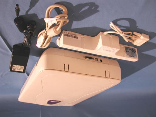
EF9MRS-600V48U
Aug 01, 2001Image Scanner
Equipment Class
JBP - Part 15 Class B Computing Device Peripheral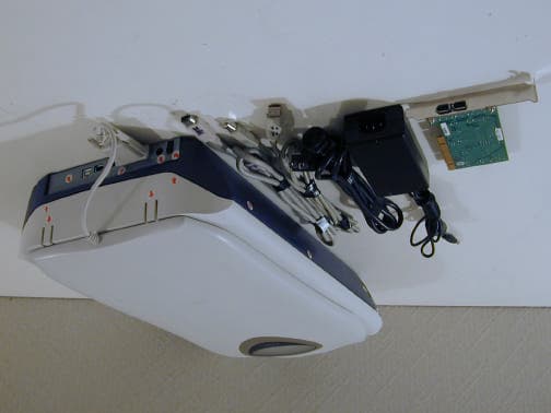
EF9MRS-4800FU
May 14, 2001Video Sender
Equipment Class
JBP - Part 15 Class B Computing Device Peripheral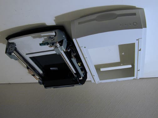
EF9DUOSCANF40
Dec 25, 2000Image Scanner
Equipment Class
JBP - Part 15 Class B Computing Device Peripheral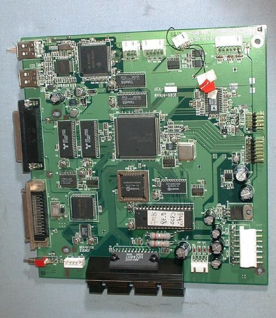
EF9DUOSCANF80
Oct 04, 2000Image Scanner With SCSI Interface
Equipment Class
JBP - Part 15 Class B Computing Device Peripheral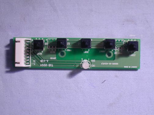
EF9MRS-2400FU
Sep 18, 2000Image Scanner With USB & 1994 Interface
Equipment Class
JBP - Part 15 Class B Computing Device Peripheral