EJM-AP310Wireless USB Adapter
Intel Corporation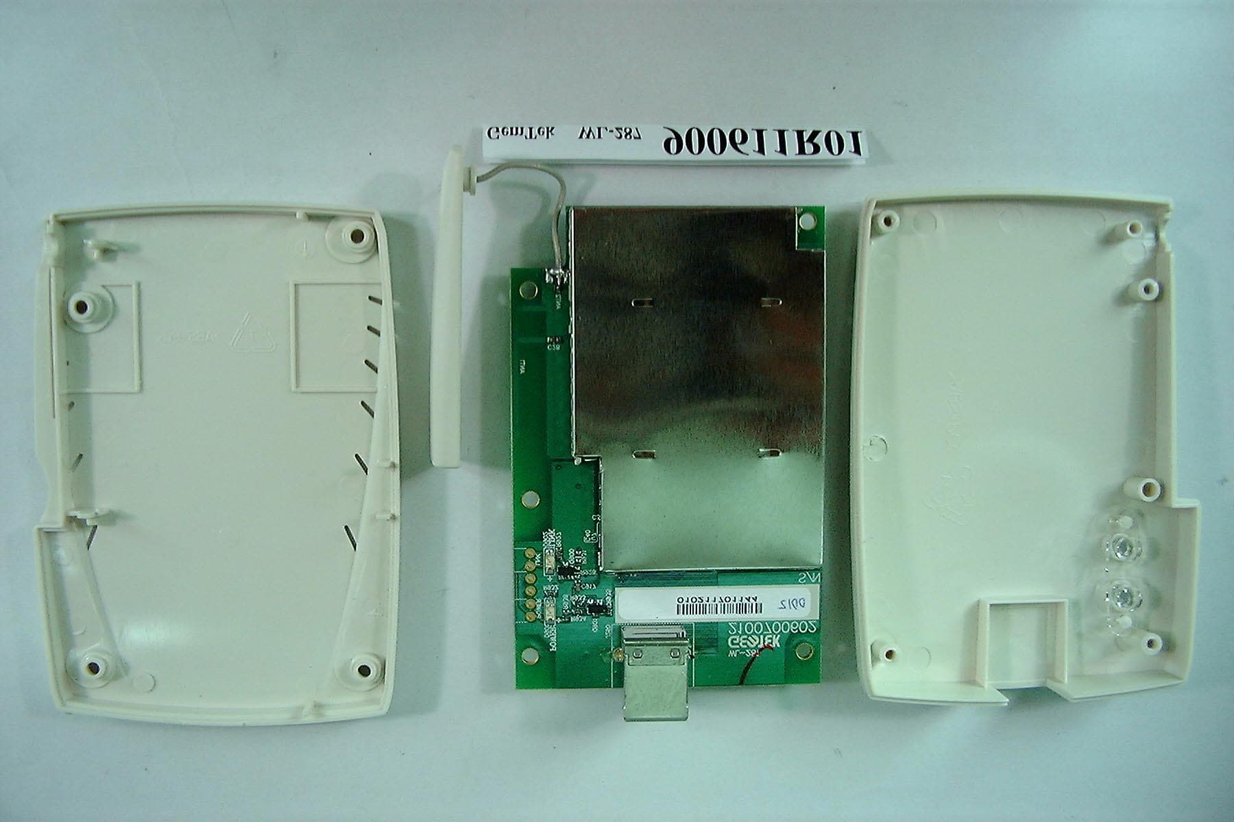
Click to zoom
Application Details
- Equipment Class
- DSS - Part 15 Spread Spectrum Transmitter
- Date of Grant
- Jul 05, 2001
- Application Purpose
- Original Equipment
- Date of Application
- Jul 05, 2001
- Equipment Note
- Wireless USB Adapter
- Frequency Range
- 2412.00000000 - 2462.00000000
- Company
- Intel Corporation
- Country
- United States
Documents & Files
Document Text
Text extracted from the exhibit documents filed with the FCC. Open a document above to read the original.
Users Manual
AnyPoint Wireless II Network User’s Guide Share internet access printers, files, games, and more... ™ ii Contents 1Understanding your AnyPoint™ Wireless II Network..................................... 1 What is a network? ............................................................................................................. 2 Components required to connect a PC to a network .......................................................... 2 Your Wireless II network adapter .............................................................................. 2 Device driver and wireless adapter settings ............................................................... 2 The AnyPoint Connectivity Software Suite CD ........................................................ 3 How does my Wireless II adapter operate?........................................................................ 3 Peer-to-Peer mode ...................................................................................................... 3 Infrastructure mode .................................................................................................... 4 How do I use my Wireless II laptop in different locations?............................................... 5 What is the AnyPoint Connection Manager? ..................................................................... 6 What are Wireless II adapter and operating system settings? .................................... 6 What is a profile? ....................................................................................................... 7 What is network switching? ....................................................................................... 7 What settings are switched in a network profile? ...................................................... 7 What is sharing and mapping? ........................................................................................... 8 What is Internet Sharing Software (ISS)? .......................................................................... 9 What is a Firewall?..................................................................................................... 9 What is Web site filtering?....................................................................................... 10 Guidelines for setting up your network............................................................................ 10 2 Set Up the AnyPoint™ Wireless II Network................................... 11 Where do I begin? ............................................................................................................ 11 Install the AnyPoint software ........................................................................................... 11 Share drives and printers .................................................................................................. 15 Configure the Internet Sharing Software (ISS) server ..................................................... 18 Configure the ISS connection .................................................................................. 19 Set up the Firewall ................................................................................................... 20 Set up Parental Control ............................................................................................ 23 Set up AnyPoint Connectivity Suite Extras ............................................................. 26 Registration ...................................................................................................................... 26 iii 3 Share Drives and Printers .......................................... 27 Use network drives........................................................................................................... 27 Use files across the network............................................................................................. 28 Viewing video files across the network ........................................................................... 28 Change drive sharing and mapping .................................................................................. 29 Change drive access ................................................................................................. 29 Change drive mapping ............................................................................................. 30 Change printer sharing and mapping ............................................................................... 30 Change printer sharing ............................................................................................. 30 Change printer mapping ........................................................................................... 30 Install printer drivers ................................................................................................ 31 Unmap a printer........................................................................................................ 31 Share and map automatically ................................................................................... 32 Multiple user profiles ....................................................................................................... 32 4 Connect to the Internet ............................................. 33 Connect to the Internet using ISS..................................................................................... 33 Connect from the ISS server .................................................................................... 33 Connect from an ISS client ...................................................................................... 34 Exiting or bypassing ISS when connecting to the Internet .............................................. 35 View connection status and settings................................................................................. 36 Change the ISS server ...........................................................................................…
Text truncated - open the document above for the full version.
Cover Letter(s)
Federal Communications Commission Authorization and Evaluation Division 7435 Oakland Mills Rd. July 3, 2001 Columbia, MD. 21046 Attention: Authorization and Evaluation Division Subject: Change of Address Dear Sir: We, ADT, as an authorized agent would like to inform you that our client, Intel Corporation has changed their contact address. Pls. refer to the following for details. OLD ADDRESS: Intel Corporation 5200 NE Elam Young Parkway MS: JF3-410 Hillsboro, OR 97124 NEW ADDRESS: Intel Corporation DP2-303 2800 Center Drive DuPont, WA 98327 Please kindly update our new address in your records. Thank You! Yours Sincerely, ---------------------------------------------- Dr. Alan Lane Manager, ADT, [email protected] Tel: +886-3-3270910 Fax: +886-3-3270892 3 th July, 2001
Cover Letter(s)
June 29, 2001 Federal Communications Commission Authorization and Evaluation Division Confidentiality Request Pursuant to Sections 0.457 and 0.459 of the Commission’s Rules, the Applicant hereby requests confidential treatment of information accompanying this Application as outlined below: Schematics Block Diagram Parts Lists Operational Descriptions Internal Photos The above materials contain trade secrets and proprietary information not customarily released to the public. The public disclosure of these matters might be harmful to the Applicant and provide unjustified benefits to its competitors. The Applicant understands that pursuant to Rule 0.457, disclosure of this Application and all accompanying documentation will not be made before the date of the Grant for this application. Sincerely, Stamped: Brian Slowik Sr. Product Regulatory Engineer Corporate Product Regulations Intel Corp. M/S DP2-303 2800 Center Drive DuPont, WA 98327-9728 ph.: 253/371-9108 fax: 253/371-9104 email: [email protected]
Cover Letter(s)
Federal Communications Commission Authorization and Evaluation Division Columbia, MD 21046 Jun 29 2001 LETTER OF AUTHORIZATION AND ANTI-DRUG ABUSE CERTIFICATION To whom it may concern: We, the undersigned, Intel Corporation hereby authorize Advance Data Technology Corp. (ADT) of Taiwan to act on our behalf in all matters relating to applications for equipment authorization, including the signing of all documents relating to these matters and payment required by FCC. Any and all acts carried out by ADT on our behalf shall have the same effect as acts of our own. We, hereby certify that we are not subject to a denial of federal benefits, that includes FCC benefits, , pursuant to Section 5301 of the Anti-Drug Abuse Act of 1988, 21 U.S.C. 853(a). Sincerely yours, Brian Slowik/Sr. Regulatory Eng. Intel Corporation. [email protected]
External Photos
FCC ID: EJM-AP310 Report No.: RF900702R01 1 Issued: July 3, 2001 ANNEX PHOTOGRAPHS OF EUT FCC ID: EJM-AP310 Report No.: RF900702R01 2 Issued: July 3, 2001 FCC ID: EJM-AP310 Report No.: RF900702R01 3 Issued: July 3, 2001
ID Label/Location Info
FCC ID: EJM-AP310 FREQ 2.4GHz LISTED I.T.E. E###### Tested To Comply With FCC Standards For Home Or Office Use CAN ############ Made in Taiwan with partial foreign content MODEL: AP310 ASSEMBLY: A65509-### SERIAL NUMBER: YWW##### 123456789012 AnyPoint TM Wireless II Network
Internal Photos
FCC ID: EJM-AP310 Report No.: RF900702R01 3 Issued: July 3, 2001 FCC ID: EJM-AP310 Report No.: RF900702R01 4 Issued: July 3, 2001 FCC ID: EJM-AP310 Report No.: RF900702R01 5 Issued: July 3, 2001
RF Exposure Info
FCC ID: EJM-AP310 ADT No.: 900702R01 RF Exposure Measurement (Mobile Device) 1. Introduction 2.4 GHz frequency band is regarded specially as a dangerous band for its heating harmfulness to the human body. That’s why microwave oven is operating in this frequency band. The manufacturer whose product is working in this frequency band is obligatory to prove the harmfulness of his product. In this document, we try to prove the safety of radiation harmfulness to the human body for our product. The limit for Maximum Permissible Exposure (MPE) specified in FCC 1.1310 is followed. The Gain of the antenna used in this product is measured in a Fully Anechoic Chamber (FAC), and the maximum total power input to the antenna is measured. Through the Friis transmission formula and the maximum gain of the antenna, we can calculate the distance, away from the product, where the limit of MPE is reached. 2. Classification The antenna of the product, under normal use condition, is easy to be relocated at least 20 cm away from the body of the user. Warning statement for keeping 20 cm separation distance and the prohibition of operating next to a person has been printed on the users manual. So, this product is classified as the Mobile Device. 3. RF Exposure Limit According to FCC 1.1310: The criteria listed in the following table shall be used to evaluate the environmental impact of human exposure to radio-frequency (RF) radiation as specified in 1.1307(b). FCC ID: EJM-AP310 ADT No.: 900702R01 LIMITS FOR MAXIMUM PERMISSIBLE EXPOSURE (MPE) Frequency Range (MHz) Electric Field Strength (V/m) Magnetic Field Strength (A/m) Power Density (mW/cm 2 ) Average Time (minutes) (A)Limits For Occupational / Control Exposures 300-1500......F/3006 1500-100,000......56 (B)Limits For General Population / Uncontrolled Exposure 300-1500......F/15006 1500-100,000......1.030 F = Frequency in MHz 4. Friis Formula Friis transmission formula : Pd = (Pout*G) / (4*pi*r 2 ) where Pd = power density in mW/cm 2 Pout = output power to antenna in mW G = gain of antenna in linear scale Pi = 3.1416 R = distance between observation point and center of the radiator in cm Pd is the limit of MPE, 1 mW/cm 2 . If we know the maximum Gain of the antenna and the total power input to the antenna, through the calculation, we will know the distance r where the MPE limit is reached. Ref. : David K. Cheng, Field and Wave Electromagnetics, Second Edition, Page 640, Eq. (11-133). 5. EUT Operating condition The software provided by Manufacturer enabled the EUT to transmit and receive data at lowest, middle and highest channel individually. FCC ID: EJM-AP310 ADT No.: 900702R01 6. Test Results 6.1 Antenna Gain The maximum Gain measured in Fully Anechoic Chamber is 1.0dBi or 1.26 (numeric). 6.2 Output Power Into Antenna & RF Exposure Distance : CHANNEL CHANNEL FREQUENCY (MHz) OUTPUT POWER TO ANTENNA (mW) MINIMUM ALLOWABLE DISTANCE ( r ) FROM SKIN (Centi-Meter) 1241260.952.47 6243763.532.52 11246265.012.55 The minimum allowable distance is very close to the enclosure of the antenna and is very far away from the human being under normal use condition.
Test Report
FCC ID: EJM-AP310 Report No.: RF900702R01 1 Issued: July 3, 2001 FCC TEST REPORT REPORT NO.: RF900702R01 MODEL NO.: AP310 RECEIVED: June 11, 2001 TESTED: June 11 ~ June 13, 2001 APPLICANT:Intel Corporation ADDRESS: DP2-303 2800 Center Drive DuPont City ISSUED BY:Advance Data Technology Corporation LAB LOCATION:47 14th Lin, Chiapau Tsun, Linko, Taipei, Taiwan, R.O.C. This test report consists of 49 pages in total. It may be duplicated completely for legal use with the approval of the applicant. It should not be reproduced except in full, without the written approval of our laboratory. The client should not use it to claim product endorsement by CNLA, NVLAP or any government agencies. The test results in the report only apply to the tested sample. 0528 Lab Code: 200102-0 FCC ID: EJM-AP310 Report No.: RF900702R01 2 Issued: July 3, 2001 Table of Contents 1CERTIFICATION ........................................................................................... 4 2SUMMARY OF TEST RESULTS................................................................... 5 3GENERAL INFORMATION ........................................................................... 6 3.1GENERAL DESCRIPTION OF EUT ............................................................. 6 3.2DESCRIPTION OF TEST MODES ............................................................... 7 3.3GENERAL DESCRIPTION OF APPLIED STANDARDS............................... 7 3.4DESCRIPTION OF SUPPORT UNITS.......................................................... 8 4TEST TYPES AND RESULTS ...................................................................... 9 4.1CONDUCTED EMISSION MEASUREMENT ................................................ 9 4.1.1LIMITS OF CONDUCTED EMISSION MEASUREMENT ............................. 9 4.1.2TEST INSTRUMENTS .................................................................................. 9 4.1.3TEST PROCEDURES................................................................................. 10 4.1.4TEST SETUP .............................................................................................. 10 4.1.5EUT OPERATING CONDITIONS.................................................................11 4.1.6TEST RESULTS.......................................................................................... 12 4.2RADIATED EMISSION MEASUREMENT ................................................... 18 4.2.1LIMITS OF RADIATED EMISSION MEASUREMENT ................................ 18 4.2.2TEST INSTRUMENTS ................................................................................ 19 4.2.3TEST PROCEDURES................................................................................. 20 4.2.4TEST SETUP .............................................................................................. 21 4.2.5EUT OPERATING CONDITIONS................................................................ 21 4.2.6TEST RESULTS.......................................................................................... 22 4.36DB BANDWIDTH MEASUREMENT.......................................................... 27 4.3.1LIMITS OF 6dB BANDWIDTH MEASUREMENT........................................ 27 4.3.2TEST INSTRUMENTS ................................................................................ 27 4.3.3TEST PROCEDURE ................................................................................... 28 4.3.4TEST SETUP .............................................................................................. 28 4.3.5EUT OPERATING CONDITIONS................................................................ 28 4.3.6TEST RESULTS.......................................................................................... 29 4.4MAXIMUM PEAK OUTPUT POWER .......................................................... 33 4.4.1LIMITS OF MAXIMUM PEAK OUTPUT POWER MEASUREMENT ........... 33 4.4.2TEST INSTRUMENTS ................................................................................ 33 4.4.3TEST PROCEDURES................................................................................. 34 4.4.4TEST SETUP .............................................................................................. 34 4.4.5EUT OPERATING CONDITIONS................................................................ 34 FCC ID: EJM-AP310 Report No.: RF900702R01 3 Issued: July 3, 2001 4.4.6TEST RESULTS.......................................................................................... 35 4.5POWER SPECTRAL DENSITY MEASUREMENT ..................................... 36 4.5.1LIMITS OF POWER SPECTRAL DENSITY MEASUREMENT ................... 36 4.5.2TEST INSTRUMENTS ................................................................................ 36 4.5.3TEST PROCEDURE ................................................................................... 37 4.5.4TEST SETUP .............................................................................................. 37 4.5.5EUT OPERATING CONDITIONS................................................................ 37 4.5.6TEST RESULTS.......................................................................................... 38 4.6BAND EDGES MEASUREMENT ................................................................ 42 4.6.1LIMITS OF BAND EDGES MEASUREMENT ............................................. 42 4.6.2TEST INSTRUMENTS ................................................................................ 42 4.6.3TEST PROCEDURE ................................................................................... 42 4.6.4EUT OPERATING CONDITION .................................................................. 43 4.6.5TEST RESULTS.......................................................................................... 43 4.7ANTENNA REQUIREMENT........................................................................ 46 4.7.1STANDARD APPLICABLE.......................................................................... 46 4.7.2ANTENNA CONNECTED C…
Text truncated - open the document above for the full version.
Test Report
FCC ID: EJM-AP310 Report No.: RF900702R01 42 Issued: July 3, 2001 4.6 BAND EDGES MEASUREMENT 4.6.1 LIMITS OF BAND EDGES MEASUREMENT Below –20dB of the highest emission level of operating band (in 100KHz Resolution Bandwidth). 4.6.2 TEST INSTRUMENTS Description & ManufacturerModel No.Serial No.Calibrated Until ROHDE & SCHWARZ TEST RECEIVER ESMI 848926/005 846839/018 Dec 28, 2001 HP ATTENUATOR8496B3247A18505 Cal. on use HP PLOTTER7475A2641V27755 N/A NOTE: 1. The measurement uncertainty is less than +/- 2.6dB, which is calculated as per the NAMAS document NIS81. 2. The calibration interval of the above test instruments is 12 months and the calibrations are traceable to NML/ROC and NIST/USA. 4.6.3 TEST PROCEDURE The transmitter output was connected to the spectrum analyzer via a low lose cable. Set both RBW and VBW of spectrum analyzer to 100 kHz with suitable frequency span including 100 kHz bandwidth from band edge. The band edges was measured and recorded. FCC ID: EJM-AP310 Report No.: RF900702R01 43 Issued: July 3, 2001 4.6.4 EUT OPERATING CONDITION Same as Item 4.3.5 4.6.5 TEST RESULTS The spectrum plots are attached on the following 2 pages. D2 line indicates the highest level, D1 line indicates the 20dB offset below D2. It shows compliance with the requirement in part 15.247(C). NOTE: The band edge emission plot on the following 2 pages shows 47.39dB delta between carrier maximum power and local maximum emission in restrict band (2484.84GHz). The emission of carrier strength list in the test result of channel 11 at the item 4.2.6 (Page 25) is 94.4dBuV/m, so the maximum field strength in restrict band is 94.9-46.67=48.23 dBuV/m which is under 54 dBuV/m limit. FCC ID: EJM-AP310 Report No.: RF900702R01 44 Issued: July 3, 2001 FCC ID: EJM-AP310 Report No.: RF900702R01 45 Issued: July 3, 2001 FCC ID: EJM-AP310 Report No.: RF900702R01 46 Issued: July 3, 2001 4.7 ANTENNA REQUIREMENT 4.7.1 STANDARD APPLICABLE For intentional device, according to FCC 47 CFR Section 15.203, an intentional radiator shall be designed to ensure that no antenna other than that furnished by the responsible party shall be used with the device. And according to FCC 47 CFR Section 15.247 (b), if transmitting antennas of directional gain greater than 6dBi are used, the power shall be reduced by the amount in dB that the directional gain of the antenna exceeds 6dBi. 4.7.2 ANTENNA CONNECTED CONSTRUCTION The antenna used in this product is monopole antenna. The antenna connector type is MCX. And the maximum Gain of this antenna is only 1dBi. FCC ID: EJM-AP310 Report No.: RF900702R01 47 Issued: July 3, 2001 5 PHOTOGRAPHS OF THE TEST CONFIGURATION CONDUCTED EMISSION TEST FCC ID: EJM-AP310 Report No.: RF900702R01 48 Issued: July 3, 2001 RADIATED EMISSION TEST FCC ID: EJM-AP310 Report No.: RF900702R01 49 Issued: July 3, 2001 6 INFORMATION ON THE TESTING LABORATORIES We, ADT Corp., were founded in 1988 to provide our best service in EMC and Safety consultation. Our laboratories are accredited and approved by the following approval agencies according to ISO/IEC 17025, Guide 25 or EN 45001: USAFCC, NVLAP GermanyTUV Rheinland JapanVCCI New ZealandMoC NorwayNEMKO R.O.C.BSMI, DGT, CNLA Copies of accreditation certificates of our laboratories obtained from approval agencies can be downloaded from our web site: www.adt.com.tw/index.5/phtml. If you have any comments, please feel free to contact us at the following: Lin Kou EMC Lab: Tel: 886-2-26052180 Fax: 886-2-26052943 Hsin Chu EMC Lab: Tel: 886-35-935343 Fax: 886-35-935342 Lin Kou Safety Lab: Tel: 886-2-26093195 Fax: 886-2-26093184 Lin Kou RF&Telecom Lab Tel: 886-3-3270910 Fax: 886-3-3270892 Email: [email protected] Web Site: www.adt.com.tw The address and road map of all our labs can be found in our web site also.
Test Report
FCC ID: EJM-AP310 Report No.: RF900702R01 1 Issued: July 3, 2001 ANNEX PROCESSING GAIN OF DIRECT SEQUENCE SPREAD SPECTRUM MEASUREMENT 1. 1.1. 1. LIMITS OF PROCESSING GAIN OF A DIRECT SEQUENCE SPREAD SPECTRUM MEASUREMENT The limit of processing gain is 10dB 1.1 TEST INSTRUMENTS & SUPPORT UNIT Description & ManufacturerModel No.Serial No. Anritsu Spectrum Analyzer, 9kHz to 30GHz MS2667CM10281 Anritsu Signal Generator, 10kHz to 20GHz 68247B984703 Hewlett Packard Power Meter,HP438A2743A04416 Hewlett Packard Power Sensor, -30 to 20dBm 8485A2942A08387 Hewlett Packard Step Attenuator, 10dB steps HP8496B3247A18505 Mini-Circuits Power SplitterZN2PD-9GNA DELL Laptop ComputerInspiron 5000eNA Campaq Laptop ComputerPPX99125 FCC ID: EJM-AP310 Report No.: RF900702R01 2 Issued: July 3, 2001 1.2 METHOD OF MEASUREMENT The processing gain may be measured using the CW jamming margin method. Section 4.7.4 shows the test configuration. The test consists of stepping a signal generator in 50 kHz increments across the passband of the system. At each point, the generator level required to produce the recommended Bit Error Rate (BER) is recorded. This level is jammer level. The output power of the transmitting unit is measured at the same point. The jammer to Signal (J/S) ratio is then calculated. Discard the worst 20% of the J/S data points. The lowest remaining J/S ratio is used when calculating the Process Gain. The reference PER is specified as 8%. The corresponding Es/No (signal to noise ratio per symbol) is 16.4 dB. The curve is attached as below. This value and the measured J/S ratio are used in the following equation to calculate the Process Gain (Gp) of the system. Where: (S/N) o : Signal to noise ratio for the chosen BER. Gp = (S/N) o +Mj+Lsys FCC ID: EJM-AP310 Report No.: RF900702R01 3 Issued: July 3, 2001 Mj : Maximum jammer to Signal Ratio recorded at the detected BER. Lsys : System losses . For the purpose of this processing gain calculation, we assume Lsys at its minimum value of 2 dB. 1.3 TEST SETUP 7 NOTEBOOK EUT ANRITSU SIGNAL GENERATOR EUT NOTEBOOK PWR SENSOR 8485A Power meter HP 438A Mini-Circuits 15542 ZNZPD-9G HP8496D STEP ATTN 110dB (10dB steps) Matched Cables RECEIVER Transmitter FCC ID: EJM-AP310 Report No.: RF900702R01 4 Issued: July 3, 2001 1.4 TEST PROCEDURES Obtain the simplex link shown. Perform all independent instrumentation calibrations prior to this procedure. Set operating power levels using fixed and variable attenuators in system to meet the following objectives: Signal Power at receiver approximately –55dBm (above thermal sensitivity such that thermal noise does not cause bit errors. Signal Power at power meter between –20 and –30dBm for optimal linearity. Use spectrum analyzer to monitor test. Ensure that CW Jammer generator RF output is disabled and measure the power at the power meter port using the power meter. This is the relative signal power, Sr. Disable Transmitter, and set CW Jammer generator RF output frequency equal to the carrier frequency and enable generator output. Set reference CW Jammer power level at power meter port 8.4dB below Sr (minimum J/S, or 10dB processing gain reference level). Note the power level setting on the generator, this is the reference CW Jammer power setting, Jr. Disable CW Jammer, re-establish link. PER test should be operating essentially error -free. Enable CW Jammer at the reference power level and verify that the PER test indicates a PER of less than 8%. Alternatively, adjust the CW Jammer level to that which causes 8% PER and verify that the S/J is less than 8.4dB. Repeat step 7 for uniform steps in frequency increments of 50 kHz across the receiver passband with the CW Jammer. In this case the receiver passband is +/- 8.5 MHz. The numerical data associated with the following radio channel is tabulated and presented for Channel 1,6, and 11. Note:Since the jamming signal will be blocked by the IF filter if the jamming frequency is far form the center of the carrier frequency. So, only those frequencies around carrier frequency are shown here. FCC ID: EJM-AP310 Report No.: RF900702R01 5 Issued: July 3, 2001 1.5 EUT OPERATING CONDITION The software provided by client to set the EUT to transmit at lowest, middle and highest channel. FCC ID: EJM-AP310 Report No.: RF900702R01 6 Issued: July 3, 2001 1.6 TEST RESULTS EUTIntel AnyPoint Wireless II Network USB Adapter ModelAP310 Environmental Conditions30°C, 65%RHTe s t e d B yGary Chang Although the theoretical processing gain is lower than 10 dB, but the CCK coding provides an extra coding gain of 2.2dB. 11Mbps CHANNEL 1 Processing Gain Gp = (S/N)。 。。 。+ Mj + Lsys Freq.Gp (S/N)。 。。 。 Mj = J/SLsysJammerLVL (GHz)(dB)(dB)(dB)(dB)(dBm)(dBm) 2.409511.316.4-7.12-47.1-0.7 2.4095511.416.4 -72-47-0.6 2.409611.416.4-72-47-0.6 2.4096511.416.4-72-47-0.6 2.409711.316.4-7.12-47.1-0.7 2.4097511.316.4-7.12-47.1-0.7 2.409811.116.4-7.32-47.3-0.9 2.4098511.116.4-7.32-47.30.9 2.40991116.4-7.42-47.4-1 2.409951116.4-7.42-47.4-1 2.4110.916.4-7.52-47.5-1.1 2.410051116.4-7.42-47.4-1 2.41011116.4-7.42-47.4-1 2.4101511.116.4-7.32-47.3-0.9 2.410211.216.4-7.22-47.2-0.8 2.4102511.316.4-7.12-47.1-0.7 2.410311.316.4-7.12-47.1-0.7 2.4103511.416.4-72-47-0.6 2.410411.316.4-7.12-47.1-0.7 2.4104511.316.4-7.12-47.1-0.7 2.410511.316.4-7.12-47.1-0.7 2.4105511.216.4-7.22-47.2-0.8 2.410611.216.4-7.22-47.2-0.8 2.4106511.316.4-7.12-47.1-0.7 2.410711.316.4-7.12-47.1-0.7 2.4107511.316.4-7.12-47.1-0.7 2.410811.416.4-72-47-0.6 2.4108511.516.4-6.92-46.9-0.5 2.410911.616.4-6.82-46.8-0.4 2.4109511.616.4-6.82-46.8-0.4 2.41111.616.4-6.82-46.8-0.4 2.4110511.416.4-72-47-0.6 2.411111.516.4-6.92-46.9-0.5 2.4111511.616.4-6.82-46.8-0.4 FCC ID: EJM-AP310 Report No.: RF900702R01 7 Issued: July 3, 2001 11Mbps CHANNEL 1 Processing Gain Gp = (S/N)+ Mj + Lsys Freq.Gp(S/N)Mj = J/SLsysJammerLVL (GHz)(dB)(dB)(dB)(dB)(dBm)(dBm) 2.411211.516.4-6.92-46.9-0.5 2.4112511.516.4-6.92-46.9-0.5 2.411311.516.4-6.92-46.9-0.5 2.4113511.416.4-72-47-0.6 2.411411.416.4-72-4…
Text truncated - open the document above for the full version.
Test Setup Photos
FCC ID: EJM-AP310 Report No.: RF900702R01 47 Issued: July 3, 2001 5 PHOTOGRAPHS OF THE TEST CONFIGURATION CONDUCTED EMISSION TEST FCC ID: EJM-AP310 Report No.: RF900702R01 48 Issued: July 3, 2001 RADIATED EMISSION TEST
Contact Information
Applicant
John Roman(Supervisor, Corporate Product Regulations)
Technical Contact
Advance Data Technology CorporationAlan Lane
[email protected]+886 3 3270910
13-1, Lane 19, WenShan 3rd st. · Taoyun · Taiwan
Test Firm
Bureau Veritas CPS (H.K.) Ltd. Taoyuan BranchRichard Chen
Technical Specifications
| # | Rule Parts | Frequency Range | Power Output |
|---|---|---|---|
| 1 | 15C | 2.41 GHz - 2.46 GHz | 65.00 mW |
Other Applications from Intel Corporation

EJM-IMOTE1
Feb 18, 2007Imote1
Equipment Class
DTS - Digital Transmission System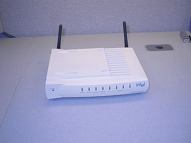
EJM-X400
Jun 27, 2002AnyPoint DSL 4400 and AnyPoint Networking 1400
Equipment Class
DSS - Part 15 Spread Spectrum Transmitter
EJM-AP1210
May 20, 2002Wireless Gateway
Equipment Class
DTS - Digital Transmission System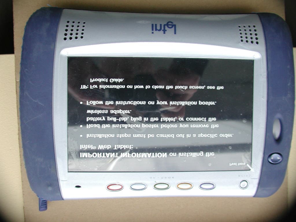
EJM-HRMP131
Mar 08, 2001Intel Web Tablet, Model 10
Equipment Class
DSS - Part 15 Spread Spectrum Transmitter
EJM-HRFUSB
Feb 08, 2001Wireless Home Network USB Adapter
Equipment Class
DSS - Part 15 Spread Spectrum Transmitter