EJM-X400AnyPoint DSL 4400 and AnyPoint Networking 1400
Intel Corporation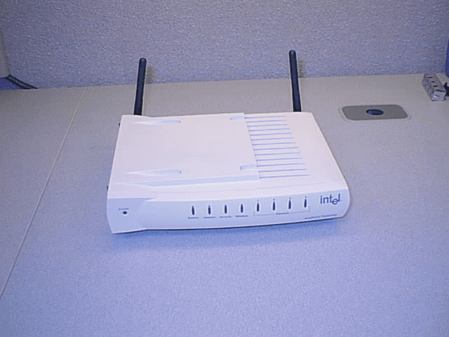
Click to zoom
Application Details
- Equipment Class
- DSS - Part 15 Spread Spectrum Transmitter
- Date of Grant
- Jun 27, 2002
- Application Purpose
- Original Equipment
- Date of Application
- Jun 27, 2002
- Equipment Note
- AnyPoint DSL 4400 and AnyPoint Networking 1400
- Frequency Range
- 2412.00000000 - 2462.00000000
- Company
- Intel Corporation
- Country
- United States
Documents & Files
Document Text
Text extracted from the exhibit documents filed with the FCC. Open a document above to read the original.
Users Manual
Exhibit T: User Manual 4400 FCC ID: EJM-X400 Share Broadband with all your PCs ® AnyPoint DSL Gateway 4400 User’s Guide Copyright The Intel ® Anypoint ® DSL Gateway 4400 User’s Guide as well as the software described in it, is furnished under license and may only be used or copied in accordance with the terms of the license. The information in this document is furnished for informational use only, is subject to change without notice, and should not be construed as a commitment by Intel Corporation. Intel Corporation assumes no responsibility or liability for any errors or inaccuracies that may appear in this document or any software that may be provided in association with this document. Except as permitted by such license, no part of this document may be reproduced, stored in a retrieval system, or transmitted in any form or by any means without the express written consent of Intel Corporation. Information in this document is provided in connection with Intel products. No license, express or implied, by estoppel or otherwise, to any intellectual property rights is granted by this document. Except as provided in Intel's Terms and Conditions of Sale for such products, Intel assumes no liability whatsoever, and Intel disclaims any express or implied warranty, relating to sale and/or use of Intel products including liability or warranties relating to fitness for a particular purpose, merchantability, or infringement of any patent, copyright or other intellectual property right. Intel products are not intended for use in medical, life saving, or life sustaining applications. Intel may make changes to specifications and product descriptions at any time, without notice. Intel, AnyPoint, and Pentium are trademarks or registered trademarks of Intel Corporation or its subsidiaries in the United States and other countries. **Other names and brands may be claimed as the property of others. Copyright (C) 2002, Intel Corporation. All rights reserved. Intel Corporation, 5200 NE Elam Young Parkway, Hillsboro, OR 97214-6497 iii Contents Introduction .......................................................................1 Overview ............................................................................................................................ 2 Intel AnyPoint DSL Gateway 4400 Features ..................................................................... 3 System Requirements ......................................................................................................... 3 Service Requirements ......................................................................................................... 4 A look at the Gateway Hardware ....................................................................................... 5 Items included with the Gateway ....................................................................................... 8 Finding Information ...........................................................................................................9 Running the Internet Setup Wizard .................................................................................... 9 Configuring your DSL Settings ......................................... 13 Specifying connection information .................................................................................. 14 Specifying a connection type ........................................................................................... 16 Specifying a PPP username and password ....................................................................... 19 Specifying an IP address .................................................................................................. 22 Specifying a name server ................................................................................................. 25 Setting up the Gateway with a Network .......................... 29 Connecting the gateway to an Ethernet hub or switch ..................................................... 30 Connecting the gateway to a wireless network ................................................................ 32 Using the Wireless Network Configuration Wizard ........................................................ 35 Specifying a wireless network name (SSID) .................................................................... 37 Correcting for wireless interference ................................................................................. 39 Changing or disabling encryption settings ....................................................................... 42 Specifying a wireless encryption key from text ............................................................... 44 Entering a key manually ................................................................................................... 46 Disabling wireless encryption .......................................................................................... 49 Configuring the gateway’s firewall .................................................................................. 51 Specifying the firewall security level ............................................................................... 53 Specifying intrusion detection settings ............................................................................ 55 Specifying IP addresses to be excluded from being blocked ........................................... 57 Using port forwarding ...................................................................................................... 59 Enabling port forwarding ................................................................................................. 61 Selecting a target computer by name ............................................................................... 63 Selecting a target computer by IP address ....................................................................... 65 Creating a custom rule ...........................................................................…
Text truncated - open the document above for the full version.
Users Manual
Exhibit Q: User Manual 1400 FCC ID: EJM-X400 Share Broadband with all your PCs ® AnyPoint Networking Gateway 1400 User’s Guide Copyright The Intel ® Anypoint ® Networking Gateway 1400 User’s Guide as well as the software described in it, is furnished under license and may only be used or copied in accordance with the terms of the license. The information in this document is furnished for informational use only, is subject to change without notice, and should not be construed as a commitment by Intel Corporation. Intel Corporation assumes no responsibility or liability for any errors or inaccuracies that may appear in this document or any software that may be provided in association with this document. Except as permitted by such license, no part of this document may be reproduced, stored in a retrieval system, or transmitted in any form or by any means without the express written consent of Intel Corporation. Information in this document is provided in connection with Intel products. No license, express or implied, by estoppel or otherwise, to any intellectual property rights is granted by this document. Except as provided in Intel's Terms and Conditions of Sale for such products, Intel assumes no liability whatsoever, and Intel disclaims any express or implied warranty, relating to sale and/or use of Intel products including liability or warranties relating to fitness for a particular purpose, merchantability, or infringement of any patent, copyright or other intellectual property right. Intel products are not intended for use in medical, life saving, or life sustaining applications. Intel may make changes to specifications and product descriptions at any time, without notice. Intel, AnyPoint, and Pentium are trademarks or registered trademarks of Intel Corporation or its subsidiaries in the United States and other countries. **Other names and brands may be claimed as the property of others. Copyright (C) 2002, Intel Corporation. All rights reserved. Intel Corporation, 5200 NE Elam Young Parkway, Hillsboro, OR 97214-6497 Product ID: FF70-1-ENU Version 3.00.00 Rev 1.00 May, 2002 iii Contents Introduction .......................................................................1 Overview ............................................................................................................................ 2 Intel AnyPoint Networking Gateway 1400 Features ......................................................... 3 System Requirements ......................................................................................................... 3 Service Requirements ......................................................................................................... 4 A look at the Gateway Hardware ....................................................................................... 4 Items included with the Gateway ....................................................................................... 8 Finding Information ...........................................................................................................9 Running the Internet Setup Wizard .................................................................................... 9 Configuring your Cable Modem Settings .........................13 Specifying an IP address .................................................................................................. 14 Specifying a name server ................................................................................................. 16 Setting up the Gateway with a Network ...........................19 Connecting the gateway to an Ethernet hub or switch ..................................................... 20 Connecting the gateway to a wireless network ................................................................ 22 Using the Wireless Network Configuration Wizard ........................................................ 25 Specifying a wireless network name (SSID) .................................................................... 27 Correcting for wireless interference ................................................................................. 29 Changing or disabling encryption settings ....................................................................... 32 Specifying a wireless encryption key from text ............................................................... 34 Entering a key manually ................................................................................................... 36 Disabling wireless encryption .......................................................................................... 39 Configuring the gateway’s firewall .................................................................................. 41 Specifying the firewall security level ............................................................................... 42 Specifying intrusion detection settings ............................................................................ 44 Specifying IP addresses to be excluded from being blocked ........................................... 47 Using port forwarding ...................................................................................................... 49 Enabling port forwarding ................................................................................................. 51 Selecting a target computer by name ............................................................................... 53 Selecting a target computer by IP address ....................................................................... 55 Creating a custom rule ...................................................................................................... 57 iv Using Advanced Configuration Options .......................... 59 Accessing advanced configuration options ...................................................................... 60 Changing the gateway password ......................................................…
Text truncated - open the document above for the full version.
Cover Letter(s)
Northwest EMC TCB Approval Opinion Revision 05/09/02 INMC0017 Information about the Applicant Company Name Intel Corporation Address 5200 NE Elam Young Parkway City, State, Zip Hillsboro, OR 97124 Requested By Michael Espig Job Number INTE4561 Model AnyPoint DSL Gateway 4400 and AnyPoint Networking Gateway 1400 FCC ID EJM-X400 Agent Applicant Approval Type Certification Equipment Type Unlicensed, low power spread spectrum transmitter Rule Part 47 CFR 15.247 Overview The applicant, Intel Corporation, has submitted all the exhibits to demonstrate compliance of their radio to 47 CFR 15.247. All the EMC testing was performed at Northwest EMC. The results are documented in the test report exhibits. The AnyPoint DSL Gateway 4400 and AnyPoint Networking Gateway 1400 use the same radio module, antennas, power supply, base board layout, and enclosure. The difference is the 4400 has a DSL interface, and the 1400 has an Ethernet interface. Both configurations were tested for radiated spurious emissions, one representative configuration was used for the antenna conducted measurements. The applicant submitted user manuals for both units. General Comments Item The TCB410 application lists two models for the application, the AnyPoint DSL 4400 and the AnyPoint Networking 1400. The user manual and the test documentation lists the EUT as the WL-350F. The application should be changed to reflect the WF-350F as the radio to be certified for use in two different configurations. Resolution A new user’s manual has been provided. All other documentation has been corrected to reflect the correct information. Item The Test Data for peak output power lists the power at 58 mW, the output power listed under the technical specs in the user manual for the WL-350F lists 13 dBm as the output power. Resolution A new user’s manual has been provided. Item The technical specifications in the user manual is for the WL-250F. If this is a mistake, it should be corrected. Resolution A new user’s manual has been provided. Northwest EMC TCB Approval Opinion Revision 05/09/02 INMC0017 Opinion Specification Requirements Description 15.207 (d) AC Powerline Conducted Emissions Opinion: The Equipment meets the intent specified by the requirements listed above. Discussion: Test data has been submitted to demonstrate compliance. Reference: Exhibit A Specification Requirements Description 15.203 Antenna Requirements Opinion: The Equipment meets the intent specified by the requirements listed above. Discussion: The Applicant has submitted technical information to demonstrate compliance. Reference: Exhibit B Specification Requirements Description 15.247 (b) De Facto EIRP Requirement of <= +36 dBm Opinion: The Equipment meets the intent specified by the requirements listed above. Discussion: The Applicant has submitted technical information to demonstrate compliance. Reference: Exhibit B & Exhibit J Specification Requirements Description 15.247 (c) Band edge compliance Opinion: The Equipment meets the intent specified by the requirements listed above. Discussion: Test data has been submitted to demonstrate compliance. Reference: Exhibit C Specification Requirements Description 2.1033 (b)(5) Frequency Block Diagram Opinion: The Equipment meets the intent specified by the requirements listed above. Discussion: The Applicant has submitted technical information to demonstrate compliance Reference: Exhibit D Northwest EMC TCB Approval Opinion Revision 05/09/02 INMC0017 Specification Requirements Description 2.1033 (b)(7) External & Internal Photos Opinion: The Equipment meets the intent specified by the requirements listed above. Discussion: The Applicant has submitted photographs to demonstrate compliance. Reference: Exhibit E & G Specification Requirements Description 2.925, 2.926, & 2.1033 (b)(7) FCC ID Label & Location Opinion: The Equipment meets the intent specified by the requirements listed above. Discussion: The Applicant has submitted an exhibit to demonstrate compliance. Reference: Exhibit F Specification Requirements Description 15.247 (a)(2) Occupied Bandwidth Opinion: The Equipment meets the intent specified by the requirements listed above. Discussion: Test data has been submitted to demonstrate compliance. Reference: Exhibit H Specification Requirements Description 2.1033 (4) Operational Description Opinion: The Equipment meets the intent specified by the requirements listed above. Discussion: The Applicant has submitted technical information to demonstrate compliance. Reference: Exhibit I Specification Requirements Description 15.247 (b) 1 Peak Output Power Opinion: The Equipment meets the intent specified by the requirements listed above. Discussion: Test data has been submitted to demonstrate compliance. Reference: Exhibit J Specification Requirements Description 15.247 (d) Power Spectral Density Opinion: The Equipment meets the intent specified by the requirements listed above. Discussion: Test data has been submitted to demonstrate compliance. Reference: Exhibit K Northwest EMC TCB Approval Opinion Revision 05/09/02 INMC0017 Specification Requirements Description 15.247 (b)(5) 1.1307, 1.1310 RF Exposure Opinion: The Equipment meets the intent specified by the requirements listed above. Discussion: The Applicant has submitted technical information to demonstrate compliance. Reference: Exhibit L Specification Requirements Description 2.1033 (b)(5) Schematics Opinion: The Equipment meets the intent specified by the requirements listed above. Discussion: The Applicant has submitted schematics to demonstrate compliance. Reference: Exhibit M Specification Requirements Description 15.247(c) Spurious Conducted Emissions Opinion: The Equipment meets the intent specified by the requirements listed above. Discussion: Test data has been submitted to demonstrate compliance Reference: Exhibit N Specification Requirements Description 15.247(c) Spurious Radiated Emissions Opinion: The Equipment meets the intent specified by the requirem…
Text truncated - open the document above for the full version.
Cover Letter(s)
Intel Corporation 5200 N.E. Elam Young Parkway Hillsboro, OR 97124-6497 USA 13 June 2002 Federal Communications Commission Authorization and Evaluation Division 7435 Oakland Mills Road Columbia, Maryland 21046 RE: FCC ID: EJM-X400 confidentiality request To whom it may concern, Pursuant to Sections 0.457 and 0.459 of the Commission’s Rules, the Applicant hereby requests confidential treatment of information accompanying this Application as outlined below: schematics block diagram The above materials contain trade secrets and proprietary information not customarily released to the public. The public disclosure of these matters might be harmful to the Applicant and provide unjustified benefits to its competitors. Any exhibit or information for which we have requested confidentiality, but which may not be accorded such treatment by the FCC, should be returned to us. We understand that pursuant to Rule 0.457, disclosure of this Application and all accompanying documentation will not be made before the date of the Grant for this application. Sincerely, Intel Corporation by: name: Brian M. Slowik title: Senior Product Regulations Engineer phone: 253 371-9108 fax: 253 371-9104 e-mail: [email protected] cc: Michael Espig
External Photos
Exhibit E: External Photos FCC ID: EJM-X400 Front view-Model 4400 Front bezel view- Model 4400
ID Label/Location Info
Exhibit F: FCC ID Label and Location FCC ID: EJM-X400 MODEL 1400 Case Label Location of case label on Model 1400
Internal Photos
Exhibit G: Internal Photos FCC ID: EJM-X400 Primary Side with add-in cards Secondary side Primary Side without add-in cards
Operational Description
Exhibit I: Operational Description FCC ID: EJM-X400 1-24-02 WL-350F MiniPCI Card Description the function in each item: 1. Fundamental frequency spec. –10 to + 70 • ±25 ppm which was generated by 44 MHz crystal oscillator(U6).It supply the reference clock to CPU and PLL. 2.Synthesizer Required frequency comes from crystal oscillator(U6),RF PLL IC(U11),IF PLL IC(U9),IF VCO(U14) etc.The frequency is controlled through CPU(U1),and generate different frequency band Which made by RF PLL and IF PLL .Receive and transmitter are same frequency;IF PLL(U13) generate 748MHz which divided by 2(U9) into 374 MHz which is IF LO.RF LO comes from VCO U14 and U11 PLL, the LO frequency is 2038—2110 MHz,step 5 Mhz,total channel 14.Transmitter/receiver freq. is 2412 and 2484 MHz. 3.Transmitter Transmitter path is through (ANT1),switch(U8),bandpass filter(FL4),IC(U11)transmitter,bandpass filter(FL5),SAW filter(FL1),Quad IF Converter(U9) to Baseband processor. Transmitter frequency, channel 1 is 2412 MHz and channel 14 is 2484MHz,each channel has 5 MHz step.Transmitter power is 12 to 13 dBm. 4.Modulation Modulation from CPU(U1),transmitter data into baseband processor generate the I,Q signal then mixed with the IFLO which is 374MHz differential signal(phase difference 90 degree)then the I,Q sum up together.The modulation are DBPSK for 1M data rate,DQPSK for 2M data rate,CCK for 5 and 11 M data rate. Demodulation:IF signal through U9 mixed with IFLO which is 374MHz differential signal (phase difference 90 degree).Generate the I,Q signal then through U1 baseband processor demodulate into data.And send to CPU (U1) for data processing. 5.Receiver RF signal 2412 to 2484 MHz ,received from antenna,bandpass TX/RX switch (U8),filter(FL6),through RF/IF converter(U11) ,mixed with RFLO down to 374MHz IF.Then IF through SAW filter into U9 mixed with IFLO which is 374MHz differential signal (phase difference 90 degree).Generate the I,Q signal then through U1 baseband processor demodulate into data.And send to CPU (U1) for data processing.Both U9 and U11 have AGC circuit to auto control the receiver signal for the best receiver sensitivity. 6.Signal Control Signal control is consist of CPU(U1) , SRAM(U4) ,Flash ROM(U2), Voltage regulator (U15/U7) 6-1.PLL control: Two PLL IC controlled by U1,one is IFLO,748MHz,the other is RFLO from 2038 to 2110 MHz,channel step 5 MHz. 6-2.TX/RX control: control the TX/RX switch(U8),U9 ,U11, U5 to perform TX/RX function. 6-3.VCO control: control the power supply of the RF VCO (U14) and IF VCO (U13) 6-4.Interface control: control Mini PCI interface through this interface communicate with system. which have TCP/IP and NDIS protocal . 6-5.Memory: In the flash memory contain the MAC address, firmware , product information ,series number and other relative information. 7.Power supply: Main power supply is from 3.3 V Mini PCI interface then into 2 regulator(U15,U7) which generate 2.85 V for RFIC and VCO. Prepared by Steven Liao Manager of R & D
RF Exposure Info
FCC ID: MXF-M900821 ADT No.: 900618R02A FCC TEST REPORT REPORT NO.: RF900618R02A MODEL NO.: WL-350F ACCORDING: FCC Guidelines for Human Exposure IEEE C95.1 APPLICANT:GEMTEK TECHNOLOGY CO., LTD. ADDRESS: No.1, Jen Ai Road, Hsinchu Industrial Park, Hukou, Hsinchu, Taiwan, R.O.C. ISSUED BY:Advance Data Technology Corporation LAB LOCATION:47 14th Lin, Chiapau Tsun, Linko, Taipei, Taiwan, R.O.C. 0528 Lab Code: 200102-0 FCC ID: MXF-M900821 ADT No.: 900618R02A RF Exposure Measurement (Mobile Device) 1. Introduction 2.4 GHz frequency band is regarded specially as a dangerous band for its heating harmfulness to the human body. That’s why microwave oven is operating in this frequency band. The manufacturer whose product is working in this frequency band is obligatory to prove the harmfulness of his product. In this document, we try to prove the safety of radiation harmfulness to the human body for our product. The limit for Maximum Permissible Exposure (MPE) specified in FCC 1.1310 is followed. The Gain of the antenna used in this product is measured in a Fully Anechoic Chamber (FAC), and the maximum total power input to the antenna is measured. Through the Friis transmission formula and the maximum gain of the antenna, we can calculate the distance, away from the product, where the limit of MPE is reached. 2. Classification The antenna of the product, under normal use condition, is at least 20 cm away from the body of the user. Warning statement for keeping 20 cm separation distance and the prohibition of operating next to a person has been printed on the users manual. So, this product is classified as the Mobile Device. 3. RF Exposure Limit According to FCC 1.1310: The criteria listed in the following table shall be used to evaluate the environmental impact of human exposure to radio-frequency (RF) radiation as specified in 1.1307(b). FCC ID: MXF-M900821 ADT No.: 900618R02A LIMITS FOR MAXIMUM PERMISSIBLE EXPOSURE (MPE) Frequency Range (MHz) Electric Field Strength (V/m) Magnetic Field Strength (A/m) Power Density (mW/cm 2 ) Average Time (minutes) (A)Limits For Occupational / Control Exposures 30-30061.40.1631.06 300-1500......F/3006 1500-100,000......56 (B)Limits For General Population / Uncontrolled Exposure 30-30027.50.0730.230 300-1500......F/150030 1500-100,000......1.030 F = Frequency in MHz 4. Friis Formula Friis transmission formula : Pd = (Pout*G) / (4*pi*r 2 ) where Pd = power density in mW/cm 2 Pout = output power to antenna in mW G = gain of antenna in linear scale Pi = 3.1416 R = distance between observation point and center of the radiator in cm Pd is the limit of MPE, 1 mW/cm 2 . If we know the maximum Gain of the antenna and the total power input to the antenna, through the calculation, we will know the distance r where the MPE limit is reached. Ref. : David K. Cheng, Field and Wave Electromagnetics, Second Edition, Page 640, Eq. (11-133). 5. EUT Operating condition The software provided by Manufacturer enabled the EUT to transmit and receive data at lowest, middle and highest channel individually. FCC ID: MXF-M900821 ADT No.: 900618R02A 6. Test Results 6.1 Antenna Gain The maximum Gain measured in Fully Anechoic Chamber is 0 dBi or 1 (numeric). 6.2 Output Power Into Antenna & RF Exposure Distance : CHANNEL CHANNEL FREQUENCY (MHz) OUTPUT POWER TO ANTENNA (mW) MINIMUM ALLOWABLE DISTANCE ( r ) FROM SKIN (Centi-Meter) 1241264.122.26 6243766.072.29 11246264.572.27 The minimum allowable distance is very close to the enclosure of the antenna and is very far away from the human being under normal use condition.
Test Report
Exhibit S: Technical Report-General Information FCC ID: EJM-X400 Measurement/Technical Report General Information Applicant: Intel Corporation Address: 5200 NE Elam Young Parkway City, State, Zip Hillsboro, OR 97124 Test Requested By: Michael Espig Models: AnyPoint DSL Gateway 4400, AnyPoint Networking Gateway 1400 FCC ID: EJM-X400 First Date of Test: May 21, 2002 Last Date of Test: May 30, 2002 Receipt Date of Samples: May 21, 2002 Job Number INTE4561 Scope Regulatory Authority Federal Communications Commission Approval Type Certification Equipment Type Unlicensed, Low Power Spread Spectrum Transmitter Rule Part 47 CFR 15.247 Rule Exemptions None Related Submittals or Grants None Report Information Prepared By Vicki Albertson, Technical Report and Documentation Manager Northwest EMC, Inc. Signature Issued By Northwest EMC, Inc. 22975 NW Evergreen Parkway, Suite 400 Hillsboro, Oregon 97124 Ph. (503) 844-4066 Fax (503) 844-3826 Report Number INTE4561 Date Issued May 30, 2002 EUT Information Frequency Range 2412 MHz – 2462 MHz Antenna Conducted Output Power 0.058 W Modulation DSSS Antenna(s) Dipole Test Facility The measurement facility used to collect the radiated and conducted data is located at Northwest EMC, Inc. 22975 NW Evergreen Parkway, Suite 400 Hillsboro, OR 97124 (503) 844-4066 Fax: 844-3826 This site has been fully described in a report filed with the FCC (Federal Communications Commission), and accepted by the FCC in a letter maintained in our files. Laboratory Accreditation Northwest EMC, Inc. is recognized under the United States Department of Commerce, National Institute of Standards and Technology, National Voluntary Laboratory Accreditation Program (NVLAP) for satisfactory compliance with criteria established in Title 15, Part 285 Code of Federal Regulations. These criteria encompass the requirements of ISO/IEC Guide 25 and the relevant requirements of ISO 9002 (ANSI/ASQC Q92-1987) as suppliers of calibration or test results. NVLAP Lab Code: 200059-0. FCC ID: EJM-X400 Exhibit A AC Powerline Conducted Emissions Exhibit B Antenna Information Exhibit C Band Edge Compliance Exhibit D Block Diagram Exhibit E External Photos Exhibit F FCC ID Label and Location Exhibit G Internal Photos Exhibit H Occupied Bandwidth Exhibit I Operational Description Exhibit J Peak Output Power Exhibit K Power Spectral Density Exhibit L RF Exposure Exhibit M Schematics Exhibit N Spurious Conducted Emissions Exhibit O Spurious Radiated Emissions Exhibit P Test Setup Photos Exhibit Q User Manual 1400 Exhibit R Request for Confidentiality Exhibit S Technical Report-General Information Exhibit T User Manual 4400
Test Report
Exhibit A: AC Powerline Conducted Emissions FCC ID: EJM-X400 Northwest EMC AC Powerline Conducted Emissions Revision 2/4/02 INTE4561 Justification The individuals and/or the organization requesting the test provided the modes, configurations and settings available to evaluate. While scanning the radiated emissions, all of the EUT parameters listed below were investigated. This includes, but may not be limited to, antennas, tuned transmit frequency ranges, operating modes, and data rates. Channels in Specified Band Investigated: High Mid Low Operating Modes Investigated: Typical Data Rates Investigated: Maximum Output Power Setting(s) Investigated: Maximum Power Input Settings Investigated: 120 VAC, 60 Hz. Frequency Range Investigated Start Frequency 450KHz Stop Frequency 30MHz Software\Firmware Applied During Test Exercise software Standard Production Software Version 2.1.0.104-4400 Description The system was tested using standard operating production software to exercise the functions of the device during the testing. The software resides in Flash on the baseboard of the EUT. Equipment Modifications No EMI suppression devices were added or modified. The EUT was tested as delivered. EUT and Peripherals D…
Text truncated - open the document above for the full version.
Contact Information
Applicant
John Roman(Supervisor, Corporate Product Regulations)
Technical Contact
Northwest EMC, Inc.Greg Kiemel
[email protected]503-844-4066
22975 NW Evergreen Parkway · Hillsboro, Oregon · United States
Non-Technical Contact
Northwest EMC, Inc.Vicki Albertson
[email protected]503-844-4066
Test Firm
Northwest EMC, Inc.Greg Kiemel
Technical Specifications
| # | Rule Parts | Frequency Range | Power Output |
|---|---|---|---|
| 1 | 15C | 2.41 GHz - 2.46 GHz | 58.00 mW |
Other Applications from Intel Corporation

EJM-IMOTE1
Feb 18, 2007Imote1
Equipment Class
DTS - Digital Transmission System
EJM-AP1210
May 20, 2002Wireless Gateway
Equipment Class
DTS - Digital Transmission System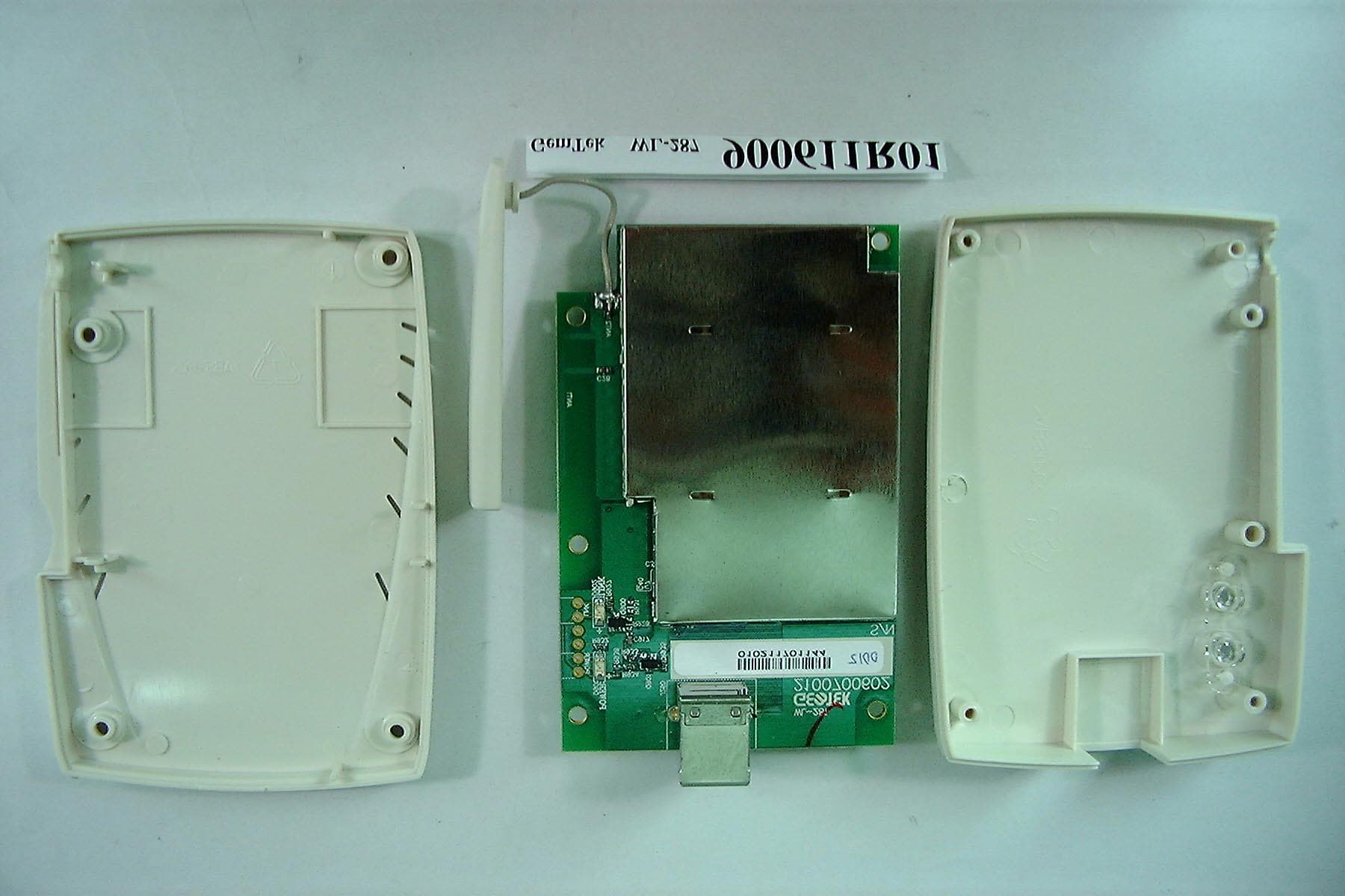
EJM-AP310
Jul 05, 2001Wireless USB Adapter
Equipment Class
DSS - Part 15 Spread Spectrum Transmitter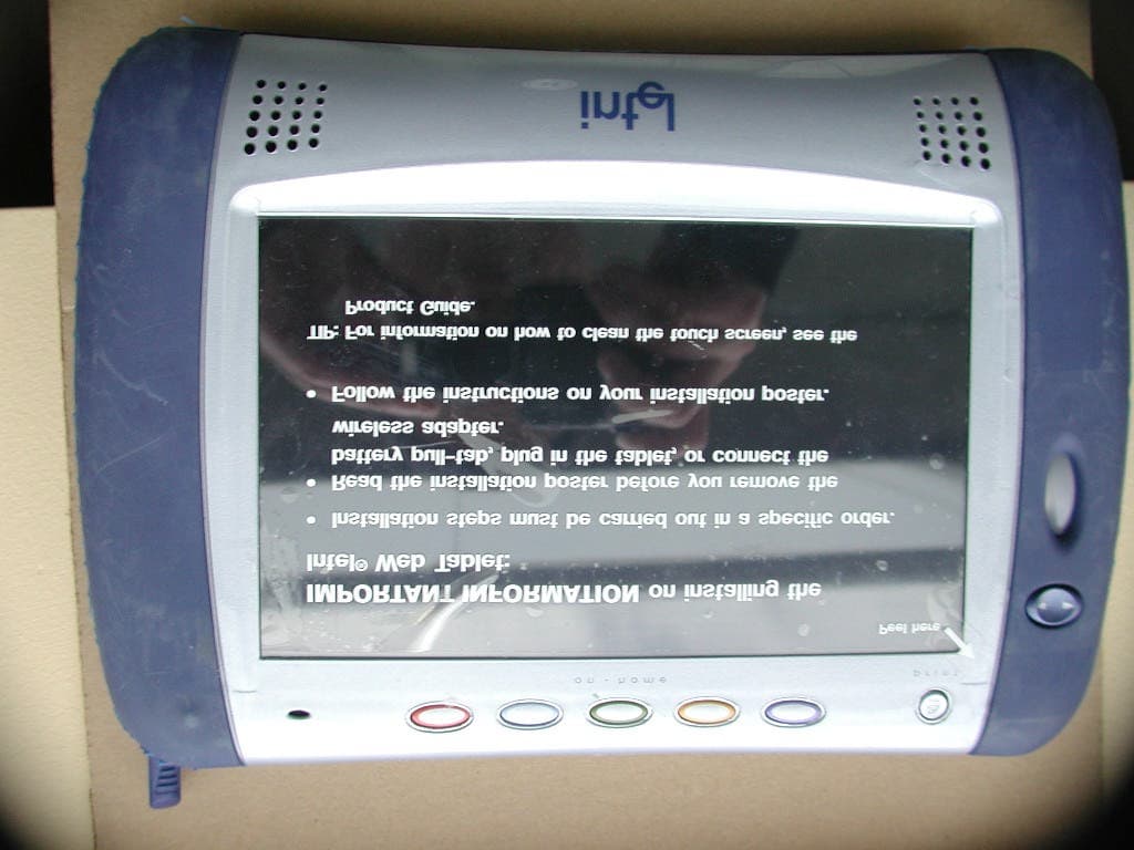
EJM-HRMP131
Mar 08, 2001Intel Web Tablet, Model 10
Equipment Class
DSS - Part 15 Spread Spectrum Transmitter
EJM-HRFUSB
Feb 08, 2001Wireless Home Network USB Adapter
Equipment Class
DSS - Part 15 Spread Spectrum Transmitter