EK2RC1930CPCS Repeater Amplifier
Repeater Technologies Inc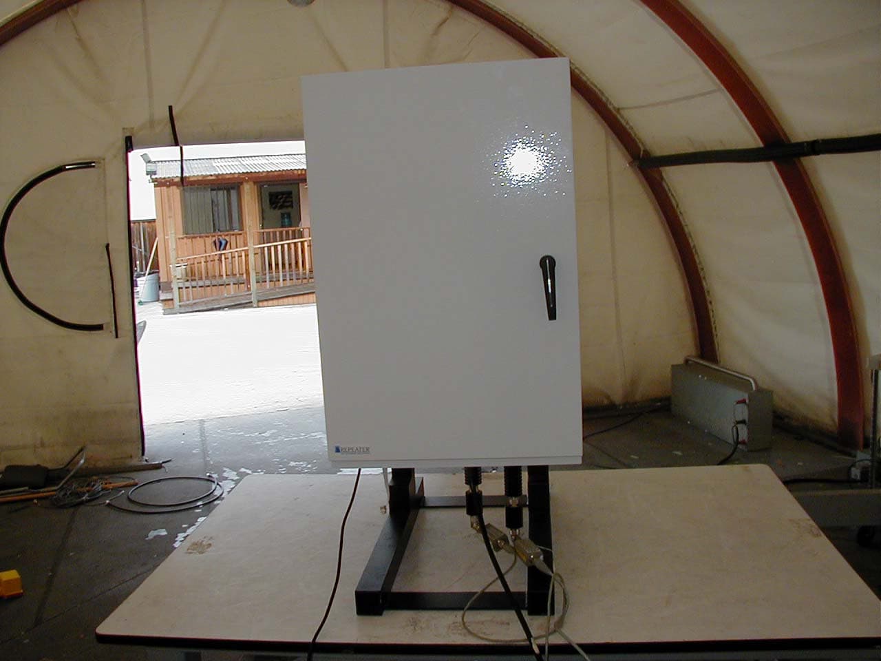
Click to zoom
Application Details
- Equipment Class
- AMP - Amplifier
- Date of Grant
- May 06, 2002
- Application Purpose
- Original Equipment
- Date of Application
- May 06, 2002
- Equipment Note
- PCS Repeater Amplifier
- Frequency Range
- 1851.25000000 - 1908.75000000
- Company
- Repeater Technologies Inc
- Country
- United States
Documents & Files
Document Text
Text extracted from the exhibit documents filed with the FCC. Open a document above to read the original.
Users Manual
550-1300-01 Revision C April 2002 Reference Manual • RC19-1X10 Network Repeater •RC19-1X15 Network Repeater • RC19-2X10 Network Repeater •RC19-2X15 Network Repeater R e f e r e n c e M a n u a l iiRTI Confidential550-1300-01 Rev C © 2002 Repeater Technologies, Inc. All rights reserved. All figures, tables, and text in this manual are the property of Repeater Technologies, Inc. (RTI). This manual provides product, ordering, installation, testing, maintenance, and applica- tion information for this product. This information is confidential; any unauthorized duplication, distribution, or electronic transfer of the materials to anyone, other than to Repeater Technologies’ authorized employees, is forbidden. By accepting this Reference Manual from Repeater Technologies, you agree to hold, in strictest confidence, the materials and information herein, and not to use or to disclose this information to any person, firm, or corporation, without the express written permis- sion of Repeater Technologies. “Confidential Information” refers to any Repeater Tech- nologies proprietary information, technical data, know-how, product plans, products, services, designs, drawings, hardware configuration information, and tables featured in this manual. This manual assumes that the installation will be performed by a qualified engineer. Repeater Technologies, Network Repeater, and RepeaterNet are trademarks of RTI. Microsoft and Windows are registered trademarks of Microsoft Corporation. Other brands and their products are trademarks or registered trademarks of their respective holders. FCC Identifiers: EK2RC1920C, TBD Industry Canada Certificate Nos. 15054, TBD Certification Nos. 2884332351, TBD Repeater Technologies, Inc. Corporate Headquarters (8 a.m. to 5p.m. Pacific Standard Time, Monday-Friday) 1150 Morse Avenue Sunnyvale, CA 94089 USA (408) 747-1900 (888) 747-1515 (USA and Canada only) Fax+1 408 747-0375 Customer Service (7 days a week, 24 hours per day) (408) 747-1946 (888) 747-1515 (USA and Canada only) www.repeaters.com Reference Manual 550-1300-01 Rev CRTI Confidentialiii Change Record Revision/IssueDateDescription of ChangeAffected Pages Issue 110/09/01Initial draft.ALL Issue 212/01/01Revise document.ALL Revison A1/18/02Production release.ALL Revision B3/7/02Revise document.ALL Revision C4/9/02Add RC19-1X15 and RC19-2X15 ModelsALL R e f e r e n c e M a n u a l ivRTI Confidential550-1300-01 Rev C Reference Manual Table of Contents 550-1300-01 Rev CRTI Confidentialv Table of Contents Chapter 1Unpacking and Inventory 1.0 Receiving and Inspecting the Repeater ..................................................... 1-1 1.1 Equipment Required for Installation ......................................................... 1-2 Chapter 2Mounting the Repeater 2.0 Installation Overview ................................................................................... 2-1 2.1 Mounting the Repeater ................................................................................ 2-3 Chapter 3Connecting Primary Power to the Repeater 3.0 Introduction ................................................................................................... 3-1 3.1 AC Power Wiring.......................................................................................... 3-2 3.2 DC Power Wiring.......................................................................................... 3-3 3.3 Wiring an External Back-up Power Supply .............................................. 3-4 3.4 Grounding...................................................................................................... 3-9 Chapter 4Installing Antennas 4.0 Moisture Protection for Antenna Connections......................................... 4-1 4.1 Antenna Configurations .............................................................................. 4-3 4.2 Antenna Cables ............................................................................................. 4-9 4.3 Lightning Protection..................................................................................... 4-9 4.4 Back-Beam Antennas and Directional Couplers .................................... 4-11 4.5 Measuring Antenna Isolation.................................................................... 4-11 4.6 Sweeping Antenna Cables ......................................................................... 4-15 Chapter 5Configuring the Repeater 5.0 RepeaterNet Craft Software ........................................................................ 5-1 5.1 Minimum System Requirements ................................................................ 5-1 5.2 Installation Procedure .................................................................................. 5-2 5.3 Configuring the Repeater Connection ....................................................... 5-3 5.4 Starting Craft ................................................................................................. 5-6 5.5 Craft Main Control Screen ........................................................................... 5-7 5.6 Status Reporting ............................................................................................ 5-8 5.7 Configuring Repeater Properties/Alarm Severities .............................. 5-27 5.8 Front End Properties .................................................................................. 5-30 Table of Contents Reference Manual viRTI Confidential550-1300-01 Rev C 5.9Channel1 and Channel2 Properties .......................................................... 5-33 5.10 Alarm Control Unit Properties.................................................................. 5-45 5.11 Remote Monitoring Properties.................................................................. 5-52 5.12 Power System Properties ........................................................................... 5-60 5.13 Back-up Power System (BUPS) Properties .............................................. 5-62 5.14 RepeaterNet M…
Text truncated - open the document above for the full version.
Cover Letter(s)
April 01, 2002 ATCB 6731 Whittier Ave Suite C110 McLean, Va. 22101 Gentlemen: The enclosed documents constitute a formal submittal and request for a Certification pursuant to Part 24 of FCC Rules (CFR 47) regarding to Personal Communication Service devices. Certification is being requested for Repeater Technology model RC19-2X15. The RC19-2X15 has been tested and found to comply with FCC Part 24 limits for intentional radiators Elliott Laboratories, as duly authorized agent prepared this submittal. A copy of the letter of our appointment as agent is enclosed. If there are any questions or if further information is needed, please contact Elliott Laboratories for assistance. Sincerely, Juan Martinez Sr. EMC Engineer JMM/dmg Enclosures: Agent Authorization Letter Confidentiality Letter Schematics External and Internal Photos Manual Theory of Operations FCC ID label and Location Emissions Test Report with Exhibits
External Photos
FRONT SIDE RIGHT SIDE LEFT SIDE BOTTOM SIDE SHOWING INPUT AND OUTPUT CONNECTORS
ID Label/Location Info
FCC ID LABEL LOCATION
Test Report
EMC Test Data Emissions Spec: Immunity Spec: Contact: Client: Model: Repeater Technologies Repeater Technologies RC19-2X15 Frank Bidwell J46669 T46670 David Bare Job Number: T-Log Number: Proj Eng: Model RC19-2X15 FCC 24E & IC-RSS133N/A Environment: Class: EMC Test Data For The T-Log: T46670 (Radio), Rev 0.1CoverPage 1 of 23 EMC Test Data The EUT is an repeater amplifier which is designed to be used with base station PCS towers. Normally, the EUT would be placed on a wall or rack during operation. The EUT was instead treated as table-top equipment during testing to simulate the end user environment. The electrical rating of the EUT is 120V, 60 Hz, 2 Amps. The EUT enclosure is primarily constructed of fabricated sheet steel. It measures approximately 20 cm wide by 16 cm deep by 30 cm high. N/A FCC ID EUT Enclosure Enter immunity spec on cover RC19-2X15amplifier Emissions Spec: DescriptionModel Repeater Technologies EUT INFORMATION Serial Number Equipment Under Test Client: Model: J46669 T46670 Repeater Technologies RC19-2X15 David Bare Job Number: T-Log Number: Proj Eng: Contact: Frank Bidwell Immunity Spec: Manufacturer General Description N/A Environment: Class:FCC 24E & IC-RSS133 Modification History Mod. #TestDateModification 1 3 2 T-Log: T46670 (Radio), Rev 0.1EUT DescripPage 2 of 23 EMC Test Data A signal generator was used to provide CDMA modulation to EUT, which was set to produce maximum output power. EUT Operation During Emissions Local Support Equipment Remote Support Equipment EUT Interface Ports FCC ID FCC ID 1xTelephoneUnterminated Emissions Spec: Immunity Spec: Contact: Manufacturer Test Configuration #1 Frank Bidwell FCC 24E & IC-RSS133 Enter immunity spec on cover N/A J46669 T46670 David Bare Job Number: T-Log Number: Proj Eng: Client: Model: Repeater Technologies RC19-2X15 Environment: Class: ModelDescriptionSerial Number ModelDescriptionSerial Number Laptop EUT Port Cable(s) Length(m)DescriptionConnected ToShielded or Unshielded N/A DellPPI None N/ADoC Manufacturer SerialLaptopRS-232 DE23520Rohde & ShwardsSMIQ 03ESignal Generator RF power port 1 & 2Spectrum AnalyzerBNC Female- 3008A07305 1.5 N/AHewlett Packard438APower Meter AC inputAC outlet3-prong USA type RJ-11 Unshielded - -- 0.8Unshielded T-Log: T46670 (Radio), Rev 0.1Test Configuration #1Page 3 of 23 EMC Test Data Client: Contact: Spec: Test Specifics General Test Configuration Ambient Conditions: Summary of Results Result Pass Pass2Output Power24.232(a) & RSS- 133(6.2) Mobile (Forward) Repeater TechnologiesJob Number: J46669 Frank Bidwell FCC 24E & IC-RSS133Class: N/A Model: RC19-2X15T-Log Number: T46670 Proj Eng: David Bare Section 2.1046 & RSS-133 (6.2): RF Power Objective: The objective of this test session is to perform final qualification testing of the EUT with respect to the specification listed above. Date of Test: 3/25/2002Config. Used: 1 Test Engineer: jmartinezConfig Change: None Test Location: SVOATS #4EUT Voltage: 120V/60Hz The EUT was located on the turntable for radiated field strength measurements and the local support equipment was located underneath the table. A power meter was used to the measure the RF power of the EUT. An attenuator was used to protect the front end of the power sensor head. Also, the attenuator value was programmed into the power meter. Temperature: 22°C Rel. Humidity: 49% Run #Test PerformedLimitComment 1Output Power24.232(a) & RSS- 133(6.2) Base (Forward) Modifications Made During Testing: No modifications were made to the EUT during testing Deviations From The Standard No deviations were made from the requirements of the standard. T-Log: T46670 (Radio), Rev 1.0RF PowerPage 4 of 23 EMC Test Data Client: Contact: Spec: Repeater TechnologiesJob Number: J46669 Frank Bidwell FCC 24E & IC-RSS133Class: N/A Model: RC19-2X15T-Log Number: T46670 Proj Eng: David Bare Run #1: Conducted Output Power (Base (forward)) Output power measured with a HP438A Power Meter and 8481A Sensor Head: BlockFreq (MHz) A1931.25 C1988.75 Attenuator value enter into power meter. Run #2: Conducted Output Power (Mobile (Reverse)) Output power measured with a HP438A Power Meter and 8481A Sensor Head: BlockFreq (MHz) A1851.25 C1908.75 Attenuator value enter into power meter. 20.000.020.00Power Meter 20.000.020.00Power Meter Comments (dBm)(dB)(dBm) Measured ValueCorredion factorPower Output 41.800.041.80Power Meter 41.700.041.70Power Meter (dBm)(dB)(dBm) Measured ValueCorredion factorPower OutputComments T-Log: T46670 (Radio), Rev 1.0RF PowerPage 5 of 23 EMC Test Data Client: Contact: Spec: Test Specifics General Test Configuration Ambient Conditions: Summary of Results Result Pass Pass Pass Pass Section 2.1049 & RSS-133 (5.6): Occupied Bandwidth Objective: The objective of this test session is to perform final qualification testing of the EUT with respect to the specification listed above. Test Location: SVOATS #4 Date of Test: 3/25/2002Config. Used: 1 Job Number: J46669 Model: RC19-2X15T-Log Number: T46670 Proj Eng: David Bare Repeater Technologies FCC 24E & IC-RSS133Class: N/A Frank Bidwell EUT Voltage: 120V/60Hz Test Engineer: jmartinezConfig Change: None LimitComment When performing conducted measurements from the EUT's antenna port, the antenna port of the EUT was connected to the spectrum analyzer or power meter via a suitable attenuator to prevent overloading the measurement system. All measurements are corrected. Modulation must not exceed manufactures stated bandwidth. Temperature: 22°C Rel. Humidity: 49% Because the EUT is an amplifer, input and output plots were made to show that the bandwidth was not altered. By altered we refer to the bandwidth increasing in width. RunTest Performed 2Occupied Bandwidth & Input - output plots 1Occupied Bandwidth & Input - output plots 3Occupied Bandwidth & Input - output plots 24.238(b) & RSS- 133(5.6) 24.238(b) & RSS- 133(5.6) 24.238(b) & RSS- 133(5.6) 4Occupied Bandwidth & Input - output plots 24.238(b) & RSS- 133(5.6) For this specific test the occupied bandwi…
Text truncated - open the document above for the full version.
Test Report
Elliott Laboratories, Inc. -- EMC Department Test Report Report Date: April 1, 2002 File: R46771 Page 3 of 15 pages Electromagnetic Emissions Test Report In Accordance With Industry Canada Radio Standards Specification 133 & FCC Part 24 Subpart E on the Repeater Amplifier Model: RC19-2X15 GRANTEE: Repeater Technologies 1150 Morse Avenue Sunnyvale, CA 94089-1605 TEST SITE: Elliott Laboratories, Inc. 684 W. Maude Ave Sunnyvale, CA 94086 REPORT DATE: April 01, 2002 FINAL TEST DATE: March 25, 2002 AUTHORIZED SIGNATORY: ______________________________ This report shall not be reproduced, except in its entirety, without the written approval of Elliott Laboratories, Inc. Elliott Laboratories, Inc. -- EMC Department Test Report Report Date: April 1, 2002 File: R46771 Page 4 of 15 pages TABLE OF CONTENTS COVER PAGE...................................................................................................................................................................................1 TABLE OF CONTENTS..............................................................................................................................................................4 FCC CERTIFICATION INFORMATION..................................................................................................................................5 SCOPE............................................................................................................................................................................................7 OBJECTIVE...................................................................................................................................................................................7 EMISSION TEST RESULTS.......................................................................................................................................................8 SECTION 2.1046: RF POWER OUTPUT.................................................................................................................................8 RSS-133 (6.2): RF POWER OUTPUT.......................................................................................................................................8 SECTION 2.1047: MODULATION CHARACTERISTICS...................................................................................................8 Section 2.1047 (d) Other types of equipment................................................................................................................8 SECTION 2.1049: OCCUPIED BANDWIDTH.......................................................................................................................9 RSS-133 (5.6): DEFINITION OF BANDWIDTH.....................................................................................................................9 SECTION 2.1051: SPURIOUS EMISSION AT ANTENNA TERMINAL...........................................................................9 RSS-133 (6.3): UNWANTED EMISSION.................................................................................................................................9 SECTION 2.1053: FIELD STRENGTH OF SPURIOUS RADIATION.................................................................................9 RSS-133(6.3): FIELD STRENGTH OF SPURIOUS RADIATION........................................................................................9 SECTION 2.1055: FREQUENCY STABILITY......................................................................................................................10 RSS-133 (7): FREQUENCY STABILITY...............................................................................................................................10 TEST SITE....................................................................................................................................................................................11 GENERAL INFORMATION...................................................................................................................................................11 CONDUCTED EMISSIONS CONSIDERATIONS...............................................................................................................11 RADIATED EMISSIONS CONSIDERATIONS..................................................................................................................11 MEASUREMENT INSTRUMENTATION................................................................................................................................12 RECEIVER SYSTEM................................................................................................................................................................12 INSTRUMENT CONTROL COMPUTER.............................................................................................................................12 POWER METER......................................................................................................................................................................12 FILTERS/ATTENUATORS....................................................................................................................................................12 ANTENNAS.............................................................................................................................................................................13 ANTENNA MAST AND EQUIPMENT TURNTABLE.....................................................................................................13 INSTRUMENT CALIBRATION............................................................................................................................................13 TEST PROCEDURES.................................................................................................................................................................14 SPECIFICATION LIMITS AND SAMPLE CALCULATIONS...................................................................…
Text truncated - open the document above for the full version.
Test Setup Photos
TEST CONFIGURATION SETUP PHOTOS PHOTO# 1 (ANTENNA CONDUCTED EMISSIONS) PHOTO# 2 (RADIATED EMISSION)
Contact Information
Applicant
Edward R Johnson(Executive Vice President)
Technical Contact
Elliott Laboratories Inc.Juan Martinez
[email protected]408-245-7899
684 West Maude Ave. · Sunnyvale, California · United States
Non-Technical Contact
Elliott Laboratories Inc.Juan Martinez
[email protected]408-245-7899
Test Firm
Elliott Laboratories LLCDavid Bare
Technical Specifications
| # | Rule Parts | Frequency Range | Power Output | Emission | Tolerance |
|---|---|---|---|---|---|
| 2 | 24E | 1.85 GHz - 1.91 GHz | 100.00 mW | 1M24F9W | Amp |
Other Applications from Repeater Technologies Inc
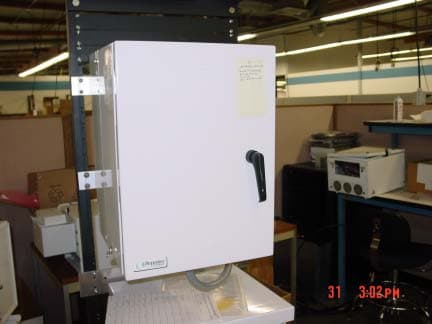
EK2RC1920C
Jan 30, 2002AMP - Amplifier
Equipment Class
AMP - Amplifier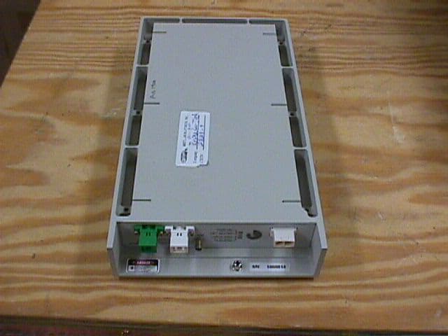
EK2OC190002
Sep 26, 2000Distributed Antenna System
Equipment Class
AMP - Amplifier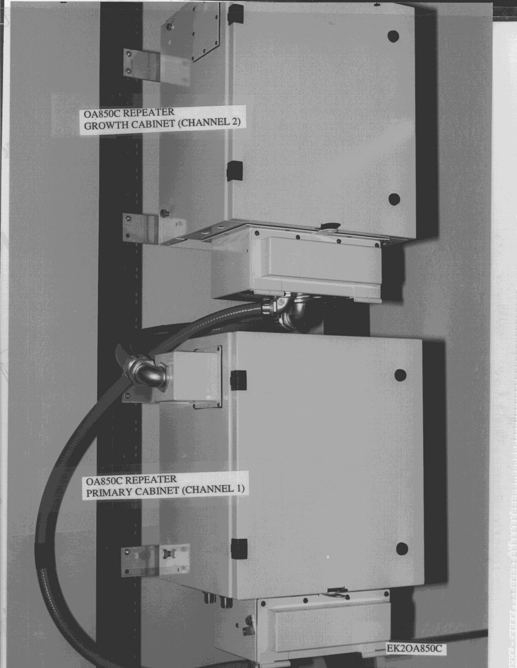
EK2OA850C
Mar 04, 1999One or two channel bi-directional repeater
Equipment Class
AMP - AmplifierEK2OA19CL3
Jan 04, 19982 Channel CDMA Extender (F9W) emissions) Listed output power is per carrier with one channel in use. Output levels reduced to 63 mW and 125 mW per carrier (for reverse and forward links) when 2 channels are used.
Equipment Class
PCB - PCS Licensed TransmitterEK2OA19CL4
Dec 14, 1997Single Channel PCS Repeater Authorized for use with CDMA signals, designated by F9W.
Equipment Class
PCB - PCS Licensed Transmitter