ELVAT0DCar Alarm Transmitter
Nutek Corporation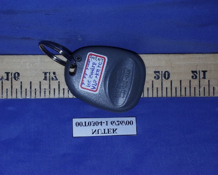
Click to zoom
Application Details
- Equipment Class
- DSC - Part 15 Security/Remote Control Transmitter
- Date of Grant
- Sep 26, 2000
- Application Purpose
- Original Equipment
- Date of Application
- Sep 26, 2000
- Equipment Note
- Car Alarm Transmitter
- Frequency Range
- 434.00000000 - 434.00000000
- Company
- Nutek Corporation
- Country
- Taiwan
Documents & Files
Document Text
Text extracted from the exhibit documents filed with the FCC. Open a document above to read the original.
ID Label/Location Info
PROPOSED FCC ID LABEL AND LOCATION NUTEK CORPORATION This device complies with Part 15 of the FCC Rules. Operation is subject to the following two conditions: (1) this device may not cause harmful interference, and (2) this device must accept any interference received, including interference that may cause undesired operation. FCC ID: ELVAT0D FCC ID LABEL
Operational Description
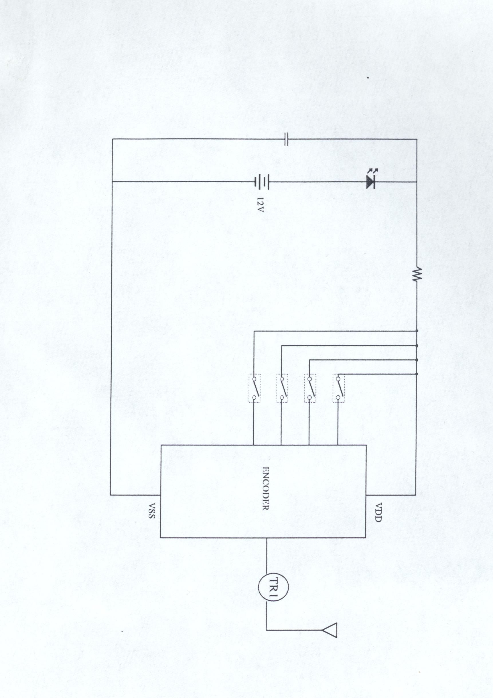
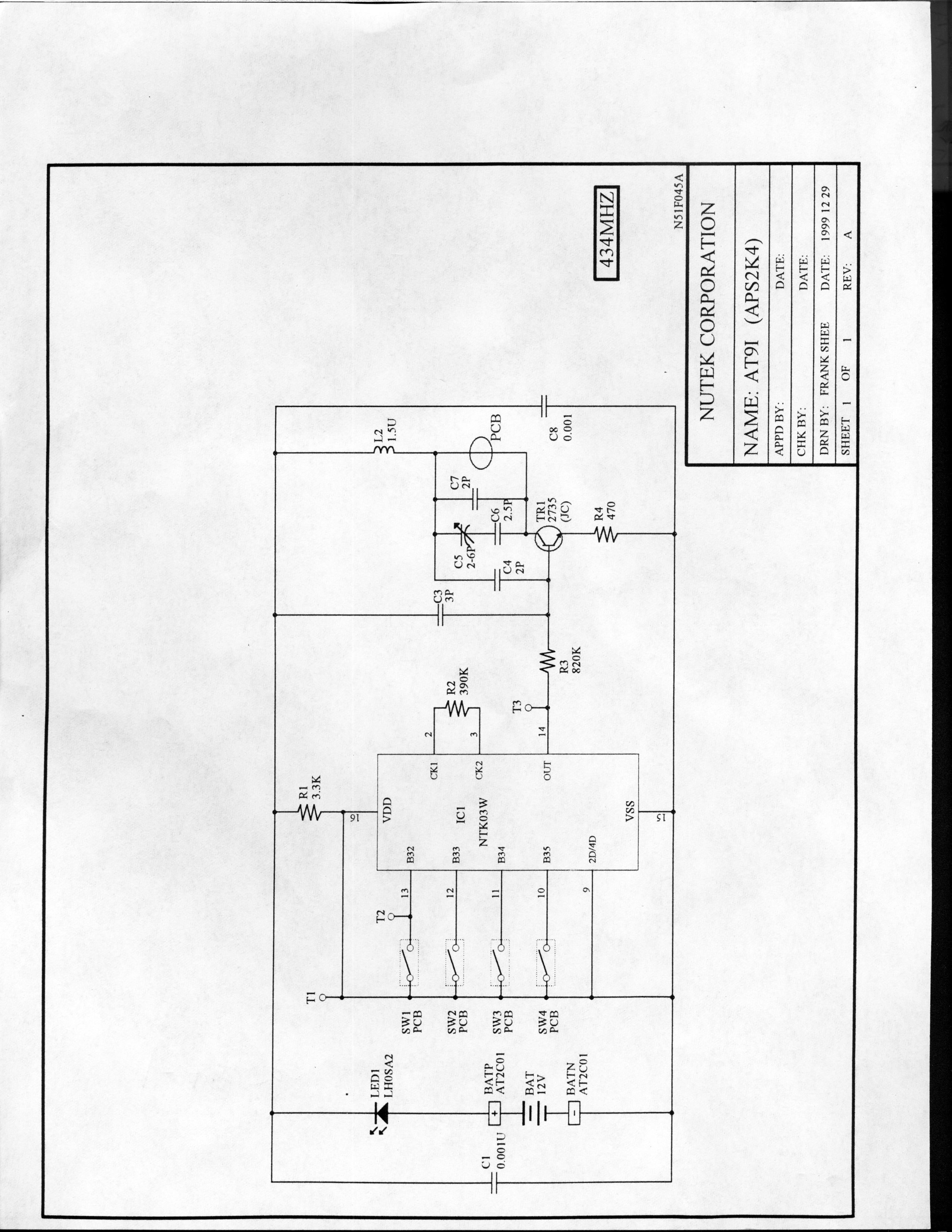
Operational Description The car alarm transmitter is a low powered, hand held unit for remote controlling the car locks and other features. The transmitter is powered by a 12 volt battery. It is designed to operated on a single fixed frequency at 434 MHz. See the attached block diagram and schematic. There are 4 buttons trigger the integrated circuit (IC1) which produces the digital control signals and will modulate the carrier signal. The carrier signal is generated by a LC circuit comprised of a 434 MHz and a npn transmitter (TR1). The transmitter is manually operated by the buttons pushed and will automatically deactivate instant after the button being released. This feature is incorporated by the IC1 internally. All tuning and verification are performed by the manufacture and there are no adjustments can be made by the user. No external ground is required or used with this transmitter.
Test Report
ELECTROMAGNETIC EMISSIONS COMPLIANCE REPORT CERTIFICATION TO FCC PART 15 REQUIREMENTS for INTENTIONAL RADIATOR 434 MHz CAR ALARM TRANSMITTER MODEL NO: APS2K4 LC FCC ID NO: ELVAT0D REPORT NO: 00T0304-1 ISSUE DATE: JUNE 22, 2000 Prepared for NUTEK CORPORATION 5F, NO. 3, ALLEY 6, LANE 45 PAO-HSING ROAD, HSIN TIEN, TAIPEI TAIWAN, R. O. C. Prepared by COMPLIANCE ENGINEERING SERVICES, INC. d.b.a. COMPLIANCE CERTIFICATION SERVICES 1366 BORDEAUX DRIVE SUNNYVALE, CA 94089, USA TEL: (408) 752-8166 FAX: (408) 752-8168 REPORT NO: 00T0304-1 FCC ID:ELVAT0D DATE: JUNE 22, 2000 COMPLIANCE ENGINEERING SERVICES, INC.CCS DOCUMENT NO:CCSUP4020B 1366 BORDEAUX DRIVE, SUNNYVALE, CA 94089, USATEL:(408)752-8166 FAX:(408)752-8168 This report shall not be reproduced except in full, without the written approval of CCS. This document may be altered or revised by Compliance Certification Services personnel only, and shall be noted in the revision section of the document. TABLE OF CONTENTS PAGE 1. VERIFICATION OF COMPLIANCE ........................................................................................ 1 2. Product Description..................................................................................................................... 2 3. Test Facility ................................................................................................................................. 2 4. Measurement Standards .............................................................................................................. 2 5. Test Methodology........................................................................................................................ 2 6. Measurement Equipment Used ...................................................................................................2 7. POWERLINE RFI LIMIT ..........................................................................................................3 8. RADIATED EMISSION LIMITS .............................................................................................. 3 9. SYSTEM TEST CONFIGURATION......................................................................................... 4 10. Test Procedure........................................................................................................................... 5 11. Equipment Modifications .......................................................................................................... 6 12. TEST RESULT ......................................................................................................................... 7 12.1 Maximum Modulation Percentage (M%) ............................................................................... 7 12.2 The Emissions Bandwidth....................................................................................................... 7 TEST DATA • Maximum Modulation Percentage Plot • Emission Bandwidth Plot • Radiated Emission Worksheet for Peak Measurement • Radiated Emission Worksheet for Average Measurement REPORT NO: 00T0304-1 FCC ID: ELVAT0D DATE: JUNE 22, 2000 PAGE NO: 1 COMPLIANCE ENGINEERING SERVICES, INC.CCS DOCUMENT NO:CCSUP4020B 1366 BORDEAUX DRIVE, SUNNYVALE, CA 94089, USATEL:(408)752-8166 FAX:(408)752-8168 This report shall not be reproduced except in full, without the written approval of CCS. This document may be altered or revised by Compliance Certification Services personnel only, and shall be noted in the revision section of the document. 1. VERIFICATION OF COMPLIANCE COMPANY NAME:NUTEK CORPORATION 5F, NO. 3, ALLEY 6, LANE 45, PAO-HSING ROAD HSIN TIEN, TAIPEI, TAIWAN R. O. C. CONTACT PERSON:RUBY HSIEH TELEPHONE NO.:02-2918-9478 EUT DESCRIPTION:434 MHz CAR ALARM TRANSMITTER MODEL NAME/NUMBER: CA-RC4PET FCC ID:ELVAT0D DATE TESTED:JUNE 22, 2000 REPORT NUMBER:00T0304 -1 TYPE OF EQUIPMENTSECURITY EQUIPMENT (INTENTIONAL RADIATOR) EQUIPMENT TYPE434 MHz CAR ALARM TRANSMITTER MEASUREMENT PROCEDUREANSI C63.4 / 1992 LIM IT TYPEC ERT IF IC AT ION FCC RULECFR 47, PART 15 The above equipment was tested by Compliance Certification Services for compliance with the requirements set forth in the FCC CFR 47, PART 15. The results of testing in this report apply to the product/system which was tested only. Other similar equipment will not necessarily produce the same results due to production tolerance and measurement uncertainties. Warning : This document reports conditions under which testing was conducted and results of tests performed. This document may not be altered or revised in any way unless done so by Compliance Certification Services and all revisions are duly noted in the revisions section. Any alteration of this document not carried out by Compliance Certification will constitute fraud and shall nullify the document. T. N. COKENIAS / ENGINEERING DIRECTOR COMPLIANCE ENGINEERING SERVICES, INC. REPORT NO: 00T0304-1 FCC ID: ELVAT0D DATE: JUNE 22, 2000 PAGE NO: 2 COMPLIANCE ENGINEERING SERVICES, INC.CCS DOCUMENT NO:CCSUP4020B 1366 BORDEAUX DRIVE, SUNNYVALE, CA 94089, USATEL:(408)752-8166 FAX:(408)752-8168 This report shall not be reproduced except in full, without the written approval of CCS. This document may be altered or revised by Compliance Certification Services personnel only, and shall be noted in the revision section of the document. 2. Product Description Fundamental Frequency 434 MHz Power Source 12V Battery Transmitting Time Periodic < 5 seconds Associated Receiver FCC ID: ELVAR5G 3. Test Facility The 3/10/30 meter open area test site and conducted measurement facility used to collect the radiated data is located at 561F Monterey Road, Morgan Hill, California, U.S.A. A detailed description of the test facility was submitted to the Commission on May 27,1994. 4. Measurement Standards The site is constructed and calibrated in conformance with the requirements of ANSI C63.4/1992. 5. Test Methodology For an intentional radiator, the spectrum shall be investigated from the lowest radio frequency signal genera…
Text truncated - open the document above for the full version.
Test Setup Photos
REPORT NO: 00T0304-1 FCC ID: ELVAT0D DATE: JUNE 22, 2000 PAGE NO: 4 COMPLIANCE ENGINEERING SERVICES, INC. CCS DOCUMENT NO:CCSUP4020B 1366 BORDEAUX DRIVE, SUNNYVALE, CA 94089, USA TEL:(408)752-8166 FAX:(408)752-8168 This report shall not be reproduced except in full, without the written approval of CCS. This document may be altered or revised by Compliance Certification Services personnel only, and shall be noted in the revision section of the document. 9. SYSTEM TEST CONFIGURATION Use a block of foam and combined it with EUT wrapping rubber band around it. This way it can test X.Y, and Z axis. To activate continuous transmission, place a small plastic block between rubber band and EUT push button. Radiated Open Site Test Set-up
Contact Information
Applicant
Jason Wang
Test Firm
Compliance Certification Services IncSteve Cheng
Technical Specifications
| # | Rule Parts | Frequency Range | Power Output |
|---|---|---|---|
| 1 | 15.231 | 434 MHz - 434 MHz | - |
Other Applications from Nutek Corporation
ELVATR6A
Sep 07, 2026Alarm module
Equipment Class
DTS - Digital Transmission SystemELVATR6B
Aug 19, 2026Vehicle Security and Remote Start System
Equipment Class
DSS - Part 15 Spread Spectrum TransmitterELVATRYA
Aug 13, 2024Transceiver
Equipment Class
DTS - Digital Transmission System
ELVMTRUE
May 29, 2021Transceiver
Equipment Class
DXX - Part 15 Low Power Communication Device Transmitter
ELVMTUD
May 24, 2021Transmitter
Equipment Class
DXX - Part 15 Low Power Communication Device Transmitter