ELVMTRUETransceiver
Nutek Corporation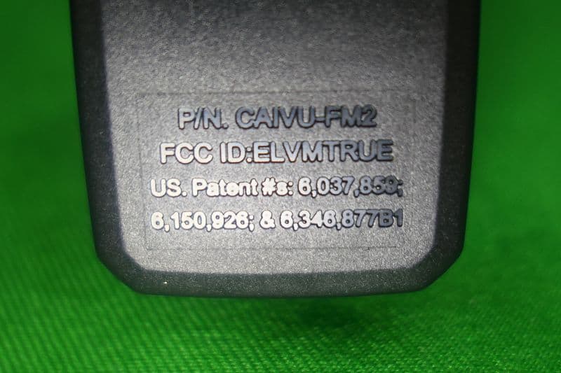
Click to zoom
Application Details
- Equipment Class
- DXX - Part 15 Low Power Communication Device Transmitter
- Date of Grant
- May 29, 2021
- Application Purpose
- Original Equipment
- Date of Application
- May 29, 2021
- Equipment Note
- Transceiver
- Frequency Range
- 903.96600000 - 917.19600000
- Company
- Nutek Corporation
- Country
- Taiwan
Documents & Files
Document Text
Text extracted from the exhibit documents filed with the FCC. Open a document above to read the original.
Users Manual
® REMOTE START with SECURITY & KEYLESS ENTRY SYSTEM Quick Reference Install Guide FOR PROFESSIONAL INSTALLATION ONLY! If you are not proficient in the installation of this product or would like a full version of the installation manual, please visit our web site @www.magnadyne.com 26 PIN (see chart) Receiver/Control Center(RCC) 2nd Sensor Port 15A 10A 20A 20A 20A Green: (+) Starter Input Violet: (+) Start Output Red / Black: (+) Battery Input (1) Orange: (+) Accessory Output Pink / Black: (+) Ignition 2/ Acc Isolation Red: +12V Battery Power Brown: (+) Siren Output Black: System Main Ground White: Parking Light Relay Output White: Parking Light Relay Power Input Blue: - Negative Door Unlock Output Green: - Negative Door Lock Output Red / White: (+) Igniton 2/ Flex Relay Pink / White: (+) 2nd Ignition or 2nd Accessory Output Pink: (+) Ignition Input/Output Red: (+) Battery Input (2) Fortin or iDatalink Bypass Module 26 10111213 1920211615141718 252423 987 22 654321 26 Pin Harness PinColorFunctionPinColorFunction 1White/Violet(-) 2nd Unlock Output14Black/Yellow(-) Dome Light Supervision Output 2Red/White(-) Channel #3 Output15Blue/White(-) 2nd Status or Rear Defog Output 3Orange(-) Ground When Armed16Dark Blue(-) 1st Status Output 4Brown(+) Brake Switch Shutdown17Green/White(-) Re-Arm the Factory Alarm Output 5Gray(-) Hood Pin Shutdown18Lt. Green/Black(-) Disarm the Factory Alarm Output 6Black/White(-) Parking Brake Switch Input19Brown/Black(-) Horn Output 7Blue(-) Instant trigger Trunk/Hood pin input20Orange/Black(-) AUX Channel #6 Output 8White/Blue(-) External Activation Input21White/Black(-) AUX Channel #5 Output 9Gray/Black(-) Diesel What to Start Input22Violet/Black(-) AUX Channel #4 Output 10Violet(+) Door Trigger Input23Violet/Yellow(-) Starter Output 11Green(-) Door Trigger Input24Orange/White(-) Accessory Output 12EMPTYNo Connection25Pink/White(-) 2nd Ignition or Acc Output 13Violet/White(AC) Tach Input26Pink(-) Ignition Output Mounting the Receiver/Control Center (RCC): 1. Choose a location on the upper or sides of the vehicle windshield. A higher location is best. 2. Remove the backing liner from the mounting tape on the backside of the RCC and stick it to the windshield glass. 3. Route the RCC cable to the location of the control module. Programming System Features: All CARBINE remote start systems have a menu of features that can be programmed to suit the installation requirements of any vehicle. These features can be set by using the RCC button learning procedure or by Windows PC programming and the CARBINE web app. Feature Programming by RCC Button 1. Open the driver’s door. 2. Turn the ignition key ON then OFF. 3. Within 5 seconds, press and hold the RCC button to select the menu. - A single chirp indicates Menu #1. - Hold the button longer for two chirps. You are in menu #2. - Continue holding the RCC button for three chirps. You are in menu #3. 4. When the desired menu is reached, release the RCC button. 5. Within 5 seconds, press and release the RCC button the number of times corresponding to the feature you want to change then press and hold the button once more to lock the feature. The siren / horn will chirp to match the feature selected. Release the RCC button. Note: RCC switch pushes are sequential. For example, if you start at feature #1, then push and release the valet switch 2 more times, you will be at feature #3 and so on. Always remember to push and hold the valet switch one more time after each selection to lock the feature before using the transmitter to change the setting. 6. Use the or buttons on the CARBINE remote to adjust the feature. 7. For features with only two options, the (lock icon) = 1 Chirp setting, while the = 2 Chirp setting. 8. For features with more than two settings, the button selects the settings in ascending order. Press and release the button as many times necessary to adjust the feature. 9. The horn/siren will chirp indicating which setting is selected. 10. Turn the ignition key to ON to exit feature programming. Menu #1 (Default in Bold) ItemFeature Chirps 123456789 1Data Protocol ADS Fortin 2 Confirmation Chirps On Off 3System Arming Active Passive 4 Door Locking Mode Active Passive 5 Forced Passive Arming On Off 6 Ignition Key Controlled Locking Off On 7 Ignition Key Controlled Unlocking Off On 8 Panic with Ignition On Off On Menu #1 continued (Default in Bold) ItemFeature Chirps 123456789 9 Armed While Driving Off On 10 Auto Starter Disable On Off 11 Door Lock Pulse 0.8 sec 3.5 sec 0.4 Sec 12Horn Output 20 ms 30 ms 40 ms 50 ms Panic Only 13 Horn Honk Mode Pulsed Constant 14 Comfort Closure Off CC1CC2 15 Tilt Sensor Adjust 3* 1.5*Off Menu #2 (Default in Bold) ItemFeature Chirps 123456789 1 Progressive Door Trigger On Off 2 Nuisance Pre- vention Circuit On Off 3 Valet Switch Pulse Count for Override 1 Pulse 2 Pulses 3 Pulses 4 Pulses 5 Pulses 4 Door Trigger Error Chirp On Off 5 Double Pulse Unlock Off On 6 Double Pulse Lock Off On 7 Ignition Key Controlled Dome Light On Off 8 Siren Duration 30 sec 60 sec 9 Factory Alarm Disarm with Trunk Release On Off 10 Factory Alarm Disarm Pulse Single Double 11 Factory Alarm Disarm With Unlock Before Unlock Remote Start Only 12 Channel #4 Linking None ArmDisarm Remote Start 13 Channel #4 Output Type Button Hold Latched Latched Off with ignition 30 sec 60 sec 90 sec 14 Channel #5 Linking None ArmDisarm Remote Start 15 Channel #5 Output Type Button Hold Latched Latched Off with ignition 30 sec 60 sec 90 sec 16 Channel #6 Linking None ArmDisarm Remote Start 17 Channel #6 Output Type Button Hold Latched Latched Off with ignition 30 Sec 60 sec 90 sec Menu #3 (Default in Bold) ItemFeature Chirps 123456789 1 Transmission Type Automatic Manual 2 Engine Checking Mode Wireless Tach Voltage Wired Tach Off 3 Cranking Duration 0.6 Sec 0.8 sec1.0 sec1.2 sec 1.4 sec 1.6 sec 1.8 sec 2.0 sec 4.0 sec 4 Remote Start Run Time 12 Minutes 24 Minutes 60 Minutes 5 Anti-Grind Output On Off 6 Diesel Start Delay Wired Wai…
Text truncated - open the document above for the full version.
Cover Letter(s)
DATE : 2021/05/25 FCC ID: ELVMTRUE D ear Sir, I hereby have entrusted the following person to be a proxy regarding application for Type Certification. Company name: Interocean EMC Technology Tin-Fu Laboratory Ad dress: No. 5-2, Lin 1, Tin-Fu, Lin-Kou Dist., New Taipei City, Taiwan 244, R.O.C. Name: Jerry Chang For instances where our authorized agent signs the application for certification on our behalf, I acknowledge that all responsibility for complying with the terms and conditions for certification, as specified by Nemko North America, Inc, still resides with us. Signature FCC grantee contact person information. N ame/Title: Jason Wang / Senior Manager Company Name: Nutek Corporation Address: No.167, Lane 235, Bauchiau Rd., Xindian District, New Taipei City 23145, Taiwan TEL: +886 2 2918 9478 FA X: +886 2 2917 9069 Em ail: [email protected]
Cover Letter(s)
DATE : 2021/0 5/25 Equipment Autorisation Division Federal Communications Commission 7 435 Oakland Mills Road Columbia, MD 21046 F CC ID: ELVMTRUE Request for Confidentiality Pursuant to Sections 0.457 and 0.459 of the commissions rules, we hereby request that the following documents be held confidential: • Schematics • Block diagram • Operation description These materials contain trade secrets and proprietary information and are not customarily released to the public. The public disclosure of this information might be harmful to the company and provide unjustified benefits to our competitors. Signature FCC grantee contact person information. Name/Title: Jason Wang / Senior Manager Company Name: Nutek Corporation Address: No.167, Lane 235, Bauchiau Rd., Xindian District, New Taipei City 23145, Taiwan TEL: +886 2 2918 9478 FAX: +886 2 2917 9069 Email: [email protected]
External Photos
Report No.: 21A032509R-FR FCC ID:ELVMTRUE Page 32 of 36 Interocean EMC Technology Corp. Test Report 7 Photographs of EUT 7.1 Model No.: CAIVU-FM2 Front View of EUT Rear View of EUT Report No.: 21A032509R-FR FCC ID:ELVMTRUE Page 33 of 36 Interocean EMC Technology Corp. Test Report FCC ID Location
Internal Photos
Report No.: 21A032509R-FR FCC ID:ELVMTRUE Page 34 of 36 Interocean EMC Technology Corp. Test Report Inner View of EUT-1 Inner View of EUT-2 Report No.: 21A032509R-FR FCC ID:ELVMTRUE Page 35 of 36 Interocean EMC Technology Corp. Test Report Component View of Main Board Solder View of Main Board Report No.: 21A032509R-FR FCC ID:ELVMTRUE Page 36 of 36 Interocean EMC Technology Corp. Test Report View of Module View of Antenna Location
Test Report
Report No.: 21A032509R-FR FCC ID:ELVMTRUE Page 1 of 36 Interocean EMC Technology Corp. Test Report 47 CFR Part 15 Subpart C Section 15.249 Test Report Product: Transceiver Trade Name: N/A Model Number: CAIVU-FM2; SLIVU-FM2 FCC ID: ELVMTRUE Prepared for Nutek Corporation No.167, Lane 235, Bauchiau Rd., Xindian District, New Taipei City 23145, Taiwan TEL.: +886 2 2918 9478 FAX.: +886 2 2917 9069 Prepared by Interocean EMC Technology Corp. Interocean EMC Technology Tin-Fu Laboratory No. 5-2, Lin 1, Tin-Fu, Lin-Kou Dist., New Taipei City, Taiwan 244, R.O.C. TEL.: +886 2 2600 6861 FAX.: +886 2 2600 6859 Remark: The test report consists of 36 pages in total. It shall not be reproduced except in full, without the written approval of IETC. This document may be altered or revised by IETC only, and shall be noted in the revision section of the document. The test result in this report is only subjected to the test sample. Report No.: 21A032509R-FR FCC ID:ELVMTRUE Page 2 of 36 Interocean EMC Technology Corp. Test Report Table of Contents 1 General Information 4 1.1 Description of Equipment Under Test 4 1.2 Table for Channel Frequencies 5 1.3 Test Facility 6 1.4 Test Equipment 7 1.5 Measurement Uncertainty 7 1.6 Summary of Measurement 8 2 Test Specifications 9 2.1 Test Standard 9 2.2 Operation Mode 9 2.3 Test Step of EUT 9 3 20dB Bandwidth test 10 3.1 Limit 10 3.2 Test Procedure 10 3.3 Test Result 10 4 RF Radiated spurious emission test 12 4.1 Limit 12 4.2 Configuration of Measurement 12 4.3 Test Procedure 13 4.4 The description of operation mode 13 4.5 Test Result 13 5 Emission on the Band Edge test 26 5.1 Limit 26 5.2 Configuration of Measurement 26 5.3 Test Procedure 26 5.4 Test Result 26 6 Photographs of Test 31 6.1 Radiated Emission Measurement (Below 1 GHz) 31 6.2 Radiated Emission Measurement (Above 1 GHz) 31 7 Photographs of EUT 32 7.1 Model No.: CAIVU-FM2 32 Report No.: 21A032509R-FR FCC ID:ELVMTRUE Page 3 of 36 Interocean EMC Technology Corp. Test Report Statement of Compliance Applicant: Nutek Corporation Manufacturer: Nutek Corporation Product: Transceiver Model No.: CAIVU-FM2; SLIVU-FM2 Tested Power Voltage: DC 5V Date of Final Test: May 14, 2021 Revision of Report: Rev. 02 Configuration of Measurements and Standards Used: FCC Rules and Regulations Part 15 Subpart C I HEREBY CERTIFY THAT: The data shown in this report were made in accordance with the procedures given in ANSI C63.10, and the energy emitted by the device was founded to be within the limits applicable. I assume full responsibility for accuracy and completeness of these data. Note: 1. The result of the testing report relate only to the item tested. 2. This report shall not be partial reproduced without written approval by Interocean EMC Technology Corporation. 3. Judgment of conformity is based on test result, regardless of measurement uncertainty. Report Issued: 2021/05/27 Prepared by: Approved: Ivan Wang Jerry Chang Report No.: 21A032509R-FR FCC ID:ELVMTRUE Page 4 of 36 Interocean EMC Technology Corp. Test Report 1 General Information 1.1 Description of Equipment Under Test Product : Transceiver Model Number : CAIVU-FM2; SLIVU-FM2 Applicant : Nutek Corporation No.167, Lane 235, Bauchiau Rd., Xindian District, New Taipei City 23145, Taiwan Manufacturer : Nutek Corporation No.167, Lane 235, Bauchiau Rd., Xindian District, New Taipei City 23145, Taiwan Power Supply : DC 5V Operating Frequency : 903.966 MHz - 917.196 MHz Output Power : 94.06 dBμV/m Channel Number : 50 channels Type of Modulation : GFSK Antenna Description : Helix Antenna. maximum Peak gain: 0dBi. Measurement Software : e3; Ver: 8.120803a7-2 Receipt Date of EUT : Apr. 13, 2021 Date of Test : Apr. 19 ~ May 14, 2021 Additional Description : 1) The test model is “CAIVU-FM2”, designated by the applicant and included in this report. 2) The differences of all models included in this report are provided by the applicant, and the lab disclaims any liability related to reporting, if incorrect, from such provision. The difference of all models is only for different market. 3) For more detailed specification about EUT, please refer to the user’s manual. Report No.: 21A032509R-FR FCC ID:ELVMTRUE Page 5 of 36 Interocean EMC Technology Corp. Test Report 1.2 Table for Channel Frequencies FC (MHz) FC (MHz) FC (MHz) FC (MHz) CH0 903.966CH13 907.476CH26 910.986CH39 914.496 CH1 904.236CH14 907.746CH27 911.256CH40 914.766 CH2 904.506CH15 908.016CH28 911.526CH41 915.036 CH3 904.776CH16 908.286CH29 911.796CH42 915.306 CH4 905.046CH17 908.556CH30 912.066CH43 915.576 CH5 905.316CH18 908.826CH31 912.336CH44 915.846 CH6 905.586CH19 909.096CH32 912.606CH45 916.116 CH7 905.856CH20 909.366CH33 912.876CH46 916.386 CH8 906.126CH21 909.636CH34 913.146CH47 916.656 CH9 906.396CH22 909.906CH35 913.416CH48 916.926 CH10 906.666CH23 910.176CH36 913.686CH49 917.196 CH11 906.936CH24 910.446CH37 913.956 CH12 907.206CH25 910.716CH38 914.226 Report No.: 21A032509R-FR FCC ID:ELVMTRUE Page 6 of 36 Interocean EMC Technology Corp. Test Report 1.3 Test Facility Site Description : Chamber 3 Name of Firm : Interocean EMC Technology Corp. Company web : http://www.ietc.com.tw Location : No. 5-2, Lin 1, Tin-Fu, Lin-Kou Dist., New Taipei City, Taiwan 244, R.O.C. Site Filing : Federal Communication Commissions – USA Designation No.: TW1020 (Test Firm Registration #: 651092) Designation No.: TW1113 (Test Firm Registration #: 959554) Innovation, Science and Economic Development Canada (ISED) CAB identifier: TW1113 (Ref. No 14962756) Voluntary Control Council for Interference by Information Technology Equipment (VCCI) – Japan Member No.: 1349 Registration No. (Conducted Room): C-11094 Registration No. (Conducted Room): T-11562 Registration No. (OATS 1): R-11040 Registration No. (Chamber 3): G-20080 Site Accreditation : Bureau of Standards and Metrology and Inspection (BSMI) – Taiwan, R.O.C. Accreditation No.: SL2-IN-E-0026 for CNS 13438 / CISPR 22 SL2-R1-E-0026 for CNS 13439 / CISPR 13 SL2-R2-E-0026 for CNS 13…
Text truncated - open the document above for the full version.
Test Setup Photos
Report No.: 21A032509R-FR FCC ID:ELVMTRUE Page 31 of 36 Interocean EMC Technology Corp. Test Report 6 Photographs of Test 6.1 Radiated Emission Measurement (Below 1 GHz) 6.2 Radiated Emission Measurement (Above 1 GHz)
Contact Information
Applicant
Jason Wang
Test Firm
Interocean EMC Technology Tin-Fu LaboratoryBenson Tsai
Technical Specifications
| # | Rule Parts | Frequency Range | Power Output |
|---|---|---|---|
| 1 | 15C | 903.966 MHz - 917.196 MHz | - |
Other Applications from Nutek Corporation
ELVATR6B
Aug 19, 2026Vehicle Security and Remote Start System
Equipment Class
DSS - Part 15 Spread Spectrum TransmitterELVATRYA
Aug 13, 2024Transceiver
Equipment Class
DTS - Digital Transmission System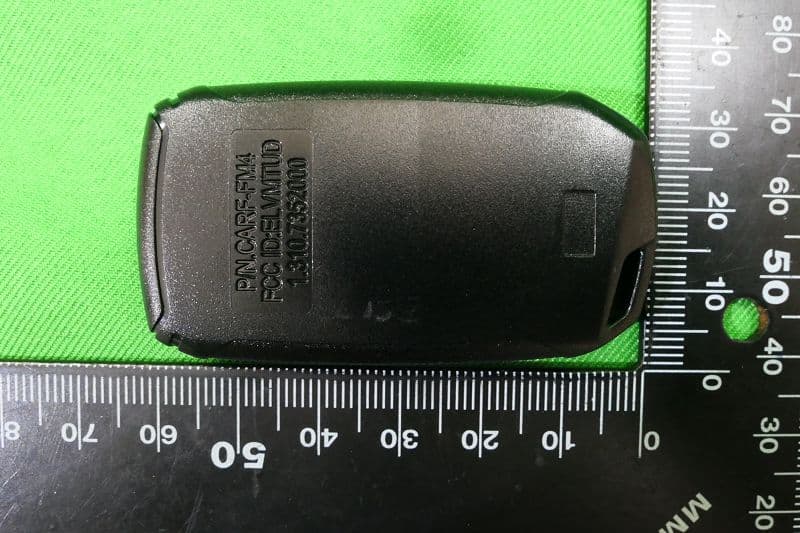
ELVMTUD
May 24, 2021Transmitter
Equipment Class
DXX - Part 15 Low Power Communication Device Transmitter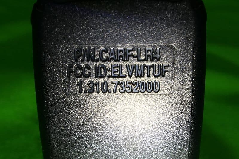
ELVMTUF
May 17, 2021Transmitter
Equipment Class
DXX - Part 15 Low Power Communication Device Transmitter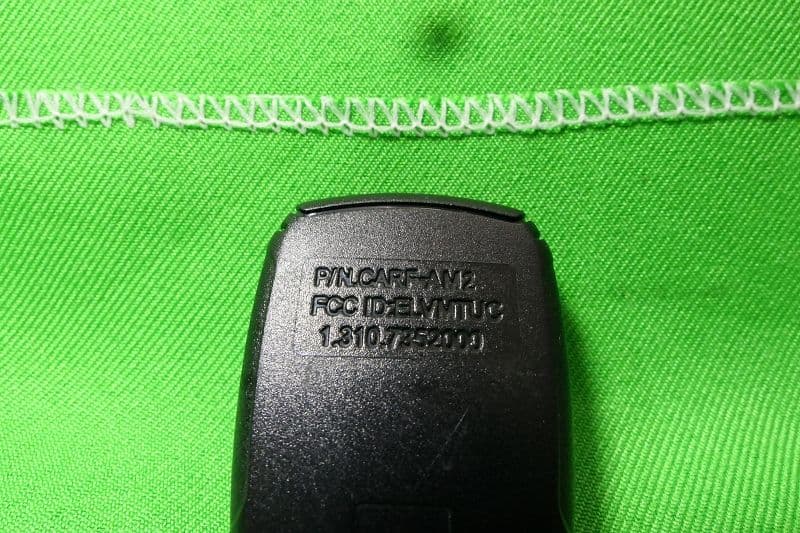
ELVMTUC
May 12, 2021Transmitter
Equipment Class
DSC - Part 15 Security/Remote Control Transmitter