ELVATGATRANSMITTER
Nutek Corporation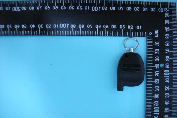
Click to zoom
Application Details
- Equipment Class
- DSC - Part 15 Security/Remote Control Transmitter
- Date of Grant
- Oct 23, 2007
- Application Purpose
- Original Equipment
- Date of Application
- Oct 23, 2007
- Equipment Note
- TRANSMITTER
- Frequency Range
- 433.91200000 - 433.91200000
- Company
- Nutek Corporation
- Country
- Taiwan
Documents & Files
Document Text
Text extracted from the exhibit documents filed with the FCC. Open a document above to read the original.
Users Manual
1 1 2 1 3 3 *4 *5 BUTTON RECEIVER CHANNEL SYSTEM FUNCTION Lock And Arm Alarm, also initiate and terminates *Panic Unlock And Disarm, also initiates and terminates *Panic. Programmable to unlock drivers door and or all doors. Lock and arm/unlock and disarm. May be programmed to unlock driver's door or all doors. Also will initiate and terminate *Panic. Pulsed or switched output to control Remote Trunk Release or optional device connected to channel 3. When pressed and release two times, will provide pulsed output or activate the Remote Start option when installed. When so equipped, this button can be used to operate an optional device connected to channel 4. When so equipped, this button can be used to operate an optional device connected to channel 5. These transmitters makes use of icons (symbols) to identify the reac- tion your security system/keyless entry/and or remote start system, where applicable, will have when any icon (button) is pressed. These icons are programmed at time of installation to meet the needs of the individual and to complement the vehicle that the system is installed in. To replace a transmitter or add transmitters, please follow the programming instructions listed on the pages of this manual. Transmitter Programming Guide * Where So Equipped 2 Some of the more popular options available for the unused Option Buttons of your transmitter are: AS 9075Remote car starter AS 9153Remote window roll up AS 9256Remote trunk release relay Although the most common use of the transmitter buttons are shown on the front page of this guide, any button or button combination can be programmed into any receiver channel. Additionally, if all 4 buttons are used and you require access to a 5th channel, you would program a combination of buttons to control the 5th function. i.e... you have programmed lock for arm, unlock for disarm, trunk for trunk release, and OPT1 for garage door operation, and you've added a window up module that you want independent control of, you would program un- lock and trunk buttons pressed simultaneously into the receiver to con- trol this function independently. Also, if you do not program a transmit- ter button into channel 2 which is the separate unlock/disarm chan- nel, then whatever button is programmed into channel 1 will serve as both lock/arm & unlock/disarm. PROGRAMMING TRANSMITTERS: NOTE:It is important to remember that during the programming mode, each individual step must be completed within 15 seconds of the previous step. If the 15 second time limit expires between steps, the unit will automatically exit the program mode. This is indicated by a long chirp from the siren. Non alarm models will flash the parking lights only to confirm the transmitter code has been learned and stored. NOTE:Because the system may be capable of sounding a siren, the vehicle horn, or both, where the siren chirp is referenced be- low, the siren may chirp, the horn may beep, or both devices may sound. Note: Some systems are capable of single button programming, if your alarm module is capable of this feature, simply complete step 4 of these programming instructions for each transmitter you wish to control your system and exit the program mode by switching off the ignition key. TO PROGRAM ADDITIONAL TRANSMITTERS: 1) Enter the vehicle, and turn the ignition switch to the on position. 2) Press and release the valet push button switch three times. Note: Some systems may use a combination push-button LED switch. In these systems the push-button and the dash mounted LED are one and the same. 3) The dash mounted LED will flash 1x, and the siren will chirp 1x, indicating that the system is ready to accept programming of channel #1 which is arm/lock, disarm/unlock/unlock 2, and panic functions. 3 4) Press and hold the lock or lock/unlock symbol button of the transmitter you wish to program for 4 seconds or until a long chirp is heard from the siren. "Repeat step 4 for each transmitter you wish to program". NOTE:If your transmitter button has the Lock/Unlock icon on one button, press and release the valet push button switch 2 times then move on to step #8. 5) Press and release the valet push button switch one time to advance to channel 2. The siren will chirp 2 times and the dash mounted LED will Flash 2 times, indicating that the unit is ready to accept programming for channel # 2 which is only used for separate lock and unlock button transmitters, and is the disarm/unlock/unlock 2 and panic. 6) Press and hold the unlock symbol button of the transmitter you wish to program for 4 seconds or until a long chirp is heard from the siren. "Repeat step 6 for each transmitter you wish to program". 7) Press and release the valet push button switch one time to advance to channel 3. The siren will chirp 3 times and the dash mounted LED will Flash 3 times, indicating that the unit is ready to accept programming for channel # 3 which is the trunk release/alternate output channel of the system. 8) Press and hold the trunk/key symbol button of the transmitter you wish to program for 4 seconds or until a long chirp is heard from the siren. "Repeat step 8 for each transmitter you wish to program". 9) Press and release the valet push button switch one time to advance to channel 4 if so equipped. The siren will chirp 4 times and the dash mounted LED will Flash 4 times, indicating that the unit is ready to accept programming for channel # 4, optional device (where equipped) 10) Press and hold the Option button of the transmitter you wish to program for 4 seconds or until a long chirp is heard from the siren. "Repeat step 10 for each transmitter you wish to program". 11) Press and release the valet push button switch one time to ad- vance to channel 5 if so equipped. The siren will chirp 5 times and the dash mounted LED will Flash 5 times, indicating that the unit is ready to accept programming for channel # 5 optional device (where equipped) 12) Press and hold the second Option button of the trans…
Text truncated - open the document above for the full version.
Cover Letter(s)
Compliance Certification Services Certification Division 561F Monterey Road Morgan Hill, CA 95037 To whom it may concern: We, the undersigned, hereby authorize ELECTRONICS TESTING CENTER, TAIWAN, to act on our behalf in all manners relating to application for equipment authorization, including signing of all documents relating to these matters. Any and all acts carried out by ELECTRONICS TESTING CENTER, TAIWAN on our behalf shall have the same effect as acts of our own. We, the undersigned, hereby certify that we are not subject to a denial of federal benefits, that includes FCC benefits, pursuant to Section 5301 of the Anti-Drug Abuse Act of 1988, 21 U.S.C. 853(a). In authorizing ELECTRONICS TESTING CENTER, TAIWAN as our agent, we still recognize that we are responsible to: a) comply with the relevant provisions of the certification program; b) make all necessary arrangements for the conduct of the evaluation, including provision for examining documentation and access to all areas, records (including internal audit reports) and personnel for the purposes of evaluation (e.g. testing, inspection, assessment, surveillance, reassessment) and resolution of complaints; c) make claims regarding certification only in respect of the scope for which certification has been granted; d) do not use our product certification in such a manner as to bring the Certification Division into disrepute and not make any statement regarding our product certification which the Certification Division may consider misleading or unauthorized; e) upon suspension or cancellation of certification, discontinue use of all advertising matter that contains any reference thereto and return any certification documents as required by the Certification Division; f) use certification only to indicate the products are certified as being in conformity with specified standards; g) endeavor to ensure that no certificate or report nor any part thereof is used in a misleading manner; h) ensure that any reference to our product certification in communication media such as documents, brochures or advertising, complies with the requirements of the Certification Division; i) keep a record of all complaints made known to the us relating to the product’s compliance with requirements of the relevant standard and to make these records available to the Certification Division when requested; j) take appropriate action with respect to such complaints and any deficiencies found in products or services that affect compliance with the requirements for certification; k) document the actions taken. This authorization is valid until further written notice from the applicant. Sincerely Yours, NUTEK CORPORATION / R&D representative NO.167, Lane 235 ,Bauchiau Rd ., Shindian City , Taipei Country 23145, Taiwan
Cover Letter(s)
Federal Communications Commission FCC ID:ELVATGA Product Name: TRANSMITTER Model Name: 07S3B Trade Name: NUTEK CORPORATION Dear Sir: In accordance with 47 C.F.R. Section 0.459, we would like to request confidentiality on some exhibits we submitted for above application for the reason of trade secret. If those exhibits are available for public inspection, any person who once gets the information contained in those exhibits will be able to design and to make the same products very easily. This is a very serious problem and huge loss for us, because we did invest so much on it. Please be not made the Exhibit Types listed below routinely available for public inspection: Block Diagram and Schematics and Operation Description. By: By: Annie (Signature) (Printed) Title : R&D representative Applicant : NUTEK CORPORATION Address : NO.167, Lane 235 ,Bauchiau Rd ., Shindian City , Taipei Country 23145, Taiwan Tel : 02-2918-9478 Fax: 02-2917-9069 Date : Oct. 01,2007
External Photos
ETC Report No.:07-09-RBF-158 Sheet 1 of 3 Sheets FCC ID.: ELVATGA Rev. No 1.0 CONSTRUCTED PHOTOS of EUT 1. Top View of EUT 2. Side View of EUT
ID Label/Location Info
BODY MATERIAL : ABS MT-11010 0.2 C ± A ±± B Eason YYS YGF 800-225-6074 FCC ID:ELVATGA PART NO.07S3B XX
Internal Photos
ETC Report No.:07-09-RBF-158 Sheet 2 of 3 Sheets FCC ID.: ELVATGA Rev. No 1.0 CONSTRUCTED PHOTOS of EUT 3. Internal View of EUT 4. Internal View of EUT ETC Report No.:07-09-RBF-158 Sheet 3 of 3 Sheets FCC ID.: ELVATGA Rev. No 1.0 CONSTRUCTED PHOTOS of EUT 5. Component View of PCB 6. Solder View of PCB
Test Report
Rev. No 1.0 FCC Part 15 EMI TEST REPORT of E.U.T. : TRANSMITTER FCC ID. : ELVATGA Model : 07S3B Working Frequency : 433.92MHz for APPLICANT : NUTEK CORPORATION ADDRESS : NO. 167, Lane 235, Bauchiau Rd., Shindian City, Taipei Country 23145, Taiwan Test Performed by ELECTRONICS TESTING CENTER, TAIWAN NO. 34, LIN 5, DING FU TSUN, LINKOU HSIANG TAIPEI HSIEN, TAIWAN, R.O.C. Tel : (02)26023052 Fax : (02)26010910 http://www.etc.org.tw ; e-mail: [email protected] Report Number : 07-09-RBF-158 ETC Report No.:07-09-RBF-158 FCC ID.: ELVATGA Rev. No 1.0 TEST REPORT CERTIFICATION Applicant : NUTEK CORPORATION NO. 167, Lane 235, Bauchiau Rd., Shindian City, Taipei Country 23145, Taiwan Manufacture : NUTEK CORPORATION NO. 167, Lane 235, Bauchiau Rd., Shindian City, Taipei Country 23145, Taiwan Description of EUT : a) Type of EUT : TRANSMITTER b) Trade Name : NUTECK CORPORATION c) Model No. : 07S3B d) FCC ID : ELVATGA e) Working Frequency : 433.92 MHz f) Power Supply : DC 3V Battery Regulation Applied : FCC Rules and Regulations Part 15 Subpart C (2007) I HEREBY CERTIFY THAT; The data shown in this report were made in accordance with the procedures given in ANSI C63.4 and the energy emitted by the device was founded to be within the limits applicable. I assume full responsibility for accuracy and completeness of these data. Note : 1. The results of the testing report relate only to the items tested. 2. The testing report shall not be reproduced except in full, without the written approval of ETC. Date Test Item Received : Sep. 29, 2007 Date Test Campaign Completed : Oct. 14, 2007 Date of Issue : Oct. 19, 2007 Test Engineer ( Kuo Chun Weng ) Approve & Authorized : Will Yauo, Manager EMC Dept. II of ELECTRONICS TESTING CENTER, TAIWAN ETC Report No.:07-09-RBF-158 FCC ID.: ELVATGA Rev. No 1.0 Table of Contents Page 1. GENERAL INFORMATION.....................................................................................................................................................1 1.1 PRODUCT DESCRIPTION...........................................................................................................................................................1 1.2 CHARACTERISTICS OF DEVICE:................................................................................................................................................1 1.3 TEST METHODOLOGY...............................................................................................................................................................1 1.4 TEST FACILITY...........................................................................................................................................................................1 2. DEFINITION AND LIMITS......................................................................................................................................................2 2.1 DEFINITION.................................................................................................................................................................................2 2.2 RESTRICTED BANDS OF OPERATION......................................................................................................................................2 2.3 LIMITATION................................................................................................................................................................................2 2.4 LABELING REQUIREMENT........................................................................................................................................................5 2.5 USER INFORMATION..................................................................................................................................................................5 3 SYSTEM TEST CONFIGURATION........................................................................................................................................6 3.1 JUSTIFICATION...........................................................................................................................................................................6 3.2 DEVICES FOR TESTED SYSTEM................................................................................................................................................6 4. RADIATED EMISSION MEASUREMENT............................................................................................................................7 4.1 APPLICABLE STANDARD.........................................................................................................................................................7 4.2 MEASUREMENT PROCEDURE...................................................................................................................................................7 4.3 TEST DATA.................................................................................................................................................................................9 4.4 FIELD STRENGTH CALCULATION.........................................................................................................................................11 4.5 ACTIVATE TIME......................................................................................................................................................................11 4.6 CALCULATION OF DUTY FACTOR........................................................................................................................................11 4.7 RADIATED TEST EQUIPMENT...............................................................................................................................................18 4.8 MEASURING INSTRUMENT SETUP........................................................................................................................................18 4.9 RADIATED MEASUREMENT PHOTOS......................................................…
Text truncated - open the document above for the full version.
Test Setup Photos
ETC Report No.:07-09-RBF-158 Sheet 19 of 23 Sheets FCC ID.: ELVATGA Rev. No 1.0 4.9 Radiated Measurement Photos
Contact Information
Applicant
Jason Wang
Test Firm
Electronics Testing Center, TaiwanWill Yauo
Technical Specifications
| # | Rule Parts | Frequency Range | Power Output |
|---|---|---|---|
| 1 | 15.231 | 433.912 MHz - 433.912 MHz | - |
Other Applications from Nutek Corporation
ELVATR6A
Sep 07, 2026Alarm module
Equipment Class
DTS - Digital Transmission SystemELVATR6B
Aug 19, 2026Vehicle Security and Remote Start System
Equipment Class
DSS - Part 15 Spread Spectrum TransmitterELVATRYA
Aug 13, 2024Transceiver
Equipment Class
DTS - Digital Transmission System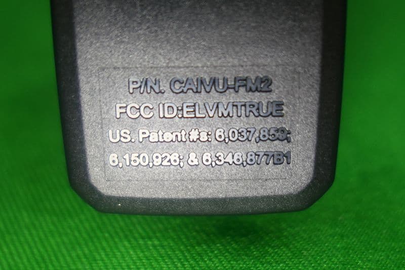
ELVMTRUE
May 29, 2021Transceiver
Equipment Class
DXX - Part 15 Low Power Communication Device Transmitter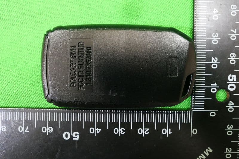
ELVMTUD
May 24, 2021Transmitter
Equipment Class
DXX - Part 15 Low Power Communication Device Transmitter