ELVATJBTransmitter
Nutek Corporation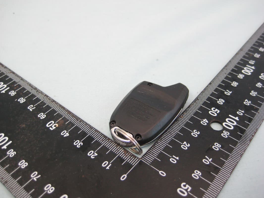
Click to zoom
Application Details
- Equipment Class
- DSC - Part 15 Security/Remote Control Transmitter
- Date of Grant
- Jun 13, 2010
- Application Purpose
- Original Equipment
- Date of Application
- Jun 13, 2010
- Equipment Note
- Transmitter
- Frequency Range
- 433.92000000 - 433.92000000
- Company
- Nutek Corporation
- Country
- Taiwan
Documents & Files
Document Text
Text extracted from the exhibit documents filed with the FCC. Open a document above to read the original.
Users Manual
128-8802 1 of 4 Transmitter Programming Guide This transmitter is designed for use with your upgrade remote start unit and is programmed by using the remote start's program switch in combination with the transmitter button. Although this transmitter can be programmed into any of the Audiovox remote start and/or alarm, remote start systems, it will offer limited use and should be used for the remote start upgrade only. To program this transmitter into your remote start upgrade unit: 1) Turn the ignition to the on position. 2) Press and release the programming switch 3 times. 3) Press and hold, for 3 seconds, the button of the transmit- ter you wish to add until the parking light flashes, indicating the transmitter has been learned. 4) Repeat step 3 for each transmitter up to a total of 4 transmitters. 5) Turn the ignition off to exit the program mode. NOTE: Do not allow more than 15 seconds to lapse between steps or the program mode will automatically exit and you will have to start over. Model 101BP 128-8802 2 of 4 Battery Replacement After removing the three #0 point phillips screws shown, pry the case apart with the edge of a finger nail or a small common screwdriver. Keep hold of the metal key ring loop to prevent its loss as it will separate from the transmitter case. Carefully remove the discharged battery by sliding it out from under the clip in the direction indicated by the arrow in the diagram below. Properly dispose of the exhausted battery and insert a new CR2032 battery taking care to arrange it so that the + is facing up toward the + symbol on the battery clip. Reassemble in the reverse of above. This device complies with FCC Rules Part 15 Operation is subject to the following two conditions: (1) This device may not cause harmful interference and (2) This device must accept any interference that may be received, including interference that may cause undesired operation. NOTE:The manufacturer is not responsible for any radio or TV interference caused by unauthorized modifications to this equipment. Such modifications could void the user’s authority to operate the equipment. 128-8802 3 of 4 Attention: Transmitter Ordering Department Important: To help us expedite your order, please print all of the information legibly and mail this form and your payment according to the instructions below. 1) Name:_____________________________________ 2) Address:_________________________________________ 3) City:________________State:________Zip Code:__________ 4 Telephone Number: ()_____________________ 5) Total Number Of Transmitters Required:_______ Cost Per Transmitter is:$65.00 Multiply By Number Of Transmitters X 6) Enter Total Amount Enclosed _______ (New York State Residents must include the appropriate sales tax.) 7) Method of Payment: Mastercard VisaCheck or Money Order (do not send cash) Make Checks Payable To Audiovox Corporation Credit Card Number:___________________________________ Credit Card Expiration Date: ____/___/____ 8) Mail this form along with your payment to: Transmitter Ordering Department Audiovox Corporation 150 Marcus Blvd., Hauppauge N.Y. 11788 Credit card purchasers can order additional or replacement transmitters by phone. Simply dial 1 - 800 - 645 - 4994, and follow the instructions from the operator interface. ORDER FORM FOR TRANSMITTER 101BP 2 128-8802 4 of 4 This Page Intentionally Left Blank © 2010 Audiovox Electronics Corp., Hauppauge, N.Y. 11788 128-8802
Cover Letter(s)
SCS-F18: Project and Product Certification Representative Authorization Letter Page 1 of 2 Rev 2.0 2206 Ringwood Avenue San Jose, CA 95131 Tel: 408-526-1188 Fax: 408-526-1088 Email: [email protected] Project and Product Certification Representative Authorization Letter Revision History Reason for Amendment (current / obsolete) From To Approved Date Initial Release (current) 1.0 1.0 Nov-14-2006 Revised wording (current) 1.0 2.0 Sept–25-2007 SCS-F18: Project and Product Certification Representative Authorization Letter Page 1 of 1 Rev 2.0 Jun. 09, 2010 To: SIEMIC, INC. 2206 Ringwood Avenue, San Jose, CA 95131 USA Dear Sir/Madam, Re: Project and Product Certification Representative Authorization Letter We, Nutek Corporation hereby authorize SIEMIC, INC. to act as a Certification Body for certifying for the following project(s): Product: Transmitter, Model No.: 101BP, FCC ID: ELVATJB We affirm that between SIEMIC and Nutek Corporation, any difference in understanding, including test plan, measurement methods, applicable standards and relevant procedures and processes have been resolved prior to commencement of testing activities. Sincerely, Charles Chen / President Nutek Corporation Tel: +886 2 2918 9478 Fax: +886 2 2917 9069 E-mail: [email protected]
External Photos
Report No.:10A053101FR FCC ID: ELVATJB Page 22 of 24 Interocean EMC Technology Corp. Test Report 7 Photographs of EUT Front View of EUT Rear View of EUT
Internal Photos
Report No.:10A053101FR FCC ID: ELVATJB Page 23 of 24 Interocean EMC Technology Corp. Test Report Inner View of EUT Antenna Location Report No.:10A053101FR FCC ID: ELVATJB Page 24 of 24 Interocean EMC Technology Corp. Test Report Component View of PCB Board Solder View of PCB Board
Test Report
Report No.:10A053101FR FCC ID: ELVATJB Page 1 of 24 Interocean EMC Technology Corp. Test Report CFR 47 FCC Part 15.231 TEST REPORT Product: Transmitter Trade Name: N/A Model Number: 101BP FCC ID: ELVATJB Prepared for Nutek Corporation NO.167, Lane 235, Bauchiau Rd., Shindian City, Taipei County 23145, Taiwan TEL.: +886 2 2918 9478 FAX.: +886 2 2917 9069 Prepared by Interocean EMC Technology Corp. 244 No.5-2, Lin 1, Tin-Fu Tsun, Lin-Kou Hsiang, Taipei County, Taiwan, R.O.C. TEL.: +886 2 2600 6861 FAX.: +886 2 2600 6859 Remark: The test report consists of 24 pages in total. It shall not be reproduced except in full, without the written approval of IETC. This document may be altered or revised by IETC only, and shall be noted in the revision section of the document. The test results in the report only to the tested sample. Report No.:10A053101FR FCC ID: ELVATJB Page 3 of 24 Interocean EMC Technology Corp. Test Report Table of Contents 1 Summary of Measurement 4 2 General Information 5 2.1 Description of Equipment Under Test 5 2.2 Details of tested peripheral equipment 6 2.3 Test Facility 7 3 Test specifications 8 3.1 Test standard 8 3.2 Operation mode 8 3.3 Test Equipment 9 4 Radiated emission test 10 4.1 Limits 10 4.2 Calculation of Average Factor 11 4.3 Configuration of Measurement 16 4.4 Test Procedure 16 4.5 Test Result 16 5 Emission bandwidth 19 5.1 Limits 19 5.2 Test Result 19 6 Photographs of Test 21 6.1 Radiated Emission Measurement 21 7 Photographs of EUT 22 Report No.:10A053101FR FCC ID: ELVATJB Page 4 of 24 Interocean EMC Technology Corp. Test Report 1 Summary of Measurement Report Clause Test Parameter Reference Document CFR47 Part15 Results 4 Radiated Emission §15.231(b), 15.209 Pass 5 Emission bandwidth §15.231(c) Pass Report No.:10A053101FR FCC ID: ELVATJB Page 5 of 24 Interocean EMC Technology Corp. Test Report 2 General Information 2.1 Description of Equipment Under Test Product : Transmitter Model Number : 101BP Applicant : Nutek Corporation NO.167, Lane 235, Bauchiau Rd., Shindian City, Taipei County 23145, Taiwan Manufacturer : Nutek Corporation NO. 167, Lane 235, Bauchiau Rd., Shindian City, Taipei County 23145, Taiwan Power Supply : 3Vdc Battery Operating Frequency : 433.92MHz Channel Number : 1 channel Type of Modulation : ASK Antenna description : This device uses Spring antenna. The antenna is integral to the device, thereby meeting the requirement of FCC 15.203. Date of Receipt Sample : May 31, 2010 Date of Test : May 31 ~ Jun. 09, 2010 Additional Description : 1) The Model Number “101BP” is representative selected in the test and included in this report. 2) For more detail specification about EUT, please refer to the user’s manual. Report No.:10A053101FR FCC ID: ELVATJB Page 6 of 24 Interocean EMC Technology Corp. Test Report 2.2 Details of tested peripheral equipment N/A Report No.:10A053101FR FCC ID: ELVATJB Page 7 of 24 Interocean EMC Technology Corp. Test Report 2.3 Test Facility Site Description : OATS 2 Name of Firm : Interocean EMC Technology Corp. Company web : http://www.ietc.com.tw Site 1, 2 Location : No.5-2, Lin 1, Tin-Fu Tsun, Lin-Kou Hsiang, Taipei County, Taiwan, R.O.C. Site 3, 4 Location : No. 12, Ruei-Shu Valley, Ruei-Ping Tsun, Lin-Kou Hsiang, Taipei County, Taiwan, R.O.C. Site Filing : z Federal Communication Commissions – USA Registration No.: 96399 (OATS 1 & 2) Registration No.: 518958 (OATS 3 & 4) Designation No.: TW1020 z Voluntary Control Council for Interference by Information Technology Equipment (VCCI) – Japan Member No.: 1349 Registration No. (Conducted Room): C-1094 Registration No. (Conducted Room): T-1562 Registration No. (OATS 1): R-1040 Registration No. (OATS 2): R-1041 z Industry Canada (IC) OUR FILE: 46405-4437 Submission: 130946 Registration No. (OATS 1): 4437A-1 Registration No. (OATS 2): 4437A-2 Registration No. (OATS 3): 4437A-3 Registration No. (OATS 4): 4437A-4 Site Accreditation : z Bureau of Standards and Metrology and Inspection (BSMI) – Taiwan, R.O.C. Accreditation No.: SL2-IN-E-0026 for CNS13438 / CISPR22 SL2-R1-E-0026 for CNS13439 / CISPR13 SL2-R2-E-0026 for CNS13439 / CISPR13 SL2-A1-E-0026 for CNS13783-1 / CISPR14-1 SL2-L1-E-0026 for CNS 14115 / CISPR 15 z Taiwan Accreditation Foundation (TAF) Accrditation No.: 1113 z TüV NORD Certificate No: TNTW0801R-02 Report No.:10A053101FR FCC ID: ELVATJB Page 8 of 24 Interocean EMC Technology Corp. Test Report 3 Test specifications 3.1 Test standard The EUT was performed according to FCC Part 15 Subpart C Section 15.231 procedure and setup followed by ANSI C63.4, 2003 requirements. 3.2 Operation mode By preliminary testing and verifying three axis (X, Y and Z) position of EUT transmitted status, it was found that “X axis” position was the worst, then the final test was executed the worst condition and test data were recorded in this report The EUT was operated in continuous transmission mode during all of the tests. X axis mode Y axis mode Z axis mode Report No.:10A053101FR FCC ID: ELVATJB Page 9 of 24 Interocean EMC Technology Corp. Test Report 3.3 Test Equipment Instrument ManufacturerModel Serial No. Next Cal. Date Spectrum Analyzer R&S FSP30 100002 2010/12/08 Spectrum Analyzer R&S FSP40 100478 2011/04/20 Preamplifier Agilent 8449B 3008A01434 2011/04/20 Preamplifier Agilent 83050A 3950A00225 2010/08/10 Preamplifier SCHAFFNER CA30100 2 2010/11/03 Horn Antenna Schwarzbeck BBHA 9120 9120D-583 2011/02/09 Wide Bandwidth Sensor Anritsu MA2491A 728133 2010/11/13 Power Meter Anritsu ML2495A 736010 2010/11/13 Temp & Humidity chamber GIAN FORCE GTH-150-40-2P-U MAA0305-012 2011/05/07 Note: The above equipments are within the valid calibration period. Report No.:10A053101FR FCC ID: ELVATJB Page 10 of 24 Interocean EMC Technology Corp. Test Report 4 Radiated emission test 4.1 Limits According to FCC 15.231(b) requirement: In addition to the provisions of §15.205, the field strength of emissions from intentional radiator operated under this section shall not exceed the following: Fundamen…
Text truncated - open the document above for the full version.
Test Setup Photos
Report No.:10A053101FR FCC ID: ELVATJB Page 21 of 24 Interocean EMC Technology Corp. Test Report 6 Photographs of Test 6.1 Radiated Emission Measurement Front View Rear View
Contact Information
Applicant
Jason Wang
Test Firm
Interocean EMC Technology Corp.Benson Tsai
Technical Specifications
| # | Rule Parts | Frequency Range | Power Output |
|---|---|---|---|
| 1 | 15.231 | 433.92 MHz - 433.92 MHz | - |
Other Applications from Nutek Corporation
ELVATR6A
Sep 07, 2026Alarm module
Equipment Class
DTS - Digital Transmission SystemELVATR6B
Aug 19, 2026Vehicle Security and Remote Start System
Equipment Class
DSS - Part 15 Spread Spectrum TransmitterELVATRYA
Aug 13, 2024Transceiver
Equipment Class
DTS - Digital Transmission System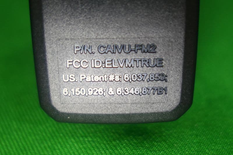
ELVMTRUE
May 29, 2021Transceiver
Equipment Class
DXX - Part 15 Low Power Communication Device Transmitter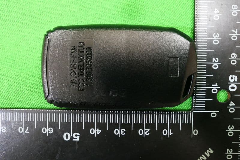
ELVMTUD
May 24, 2021Transmitter
Equipment Class
DXX - Part 15 Low Power Communication Device Transmitter