ELVATNBTransmitter
Nutek Corporation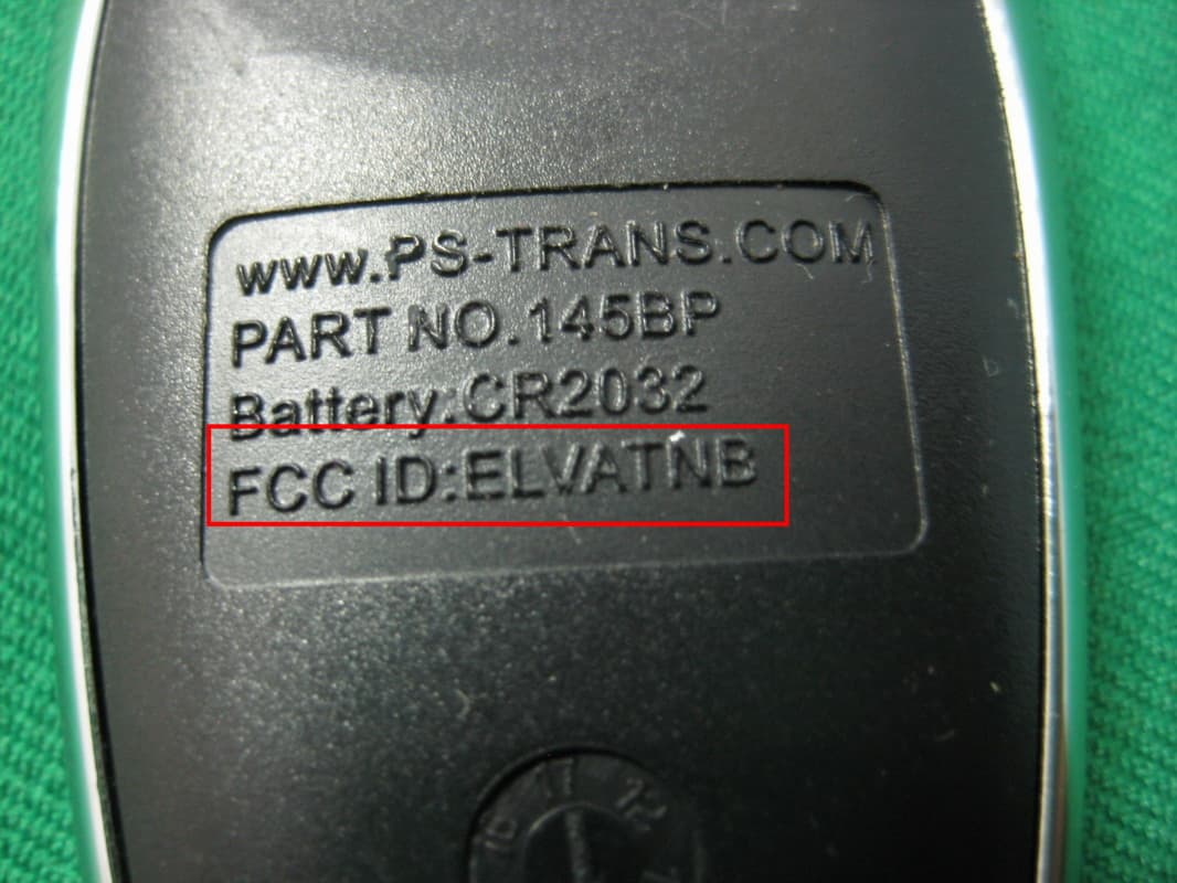
Click to zoom
Application Details
- Equipment Class
- DSC - Part 15 Security/Remote Control Transmitter
- Date of Grant
- Jul 29, 2014
- Application Purpose
- Original Equipment
- Date of Application
- Jul 29, 2014
- Equipment Note
- Transmitter
- Frequency Range
- 433.92000000 - 433.92000000
- Company
- Nutek Corporation
- Country
- Taiwan
Documents & Files
Document Text
Text extracted from the exhibit documents filed with the FCC. Open a document above to read the original.
Users Manual
128-9313 1 of 16 Page 1 PATENTED: www.voxxintl.com/company/patents Model APS-510E 5 Button Remote Security System with Dual Stage Shock Sensor Owners Guide FCC COMPLIANCE This device complies with Part 15 of the FCC rules and with RSS-210 of Industry Canada. Operation is subject to the following two conditions: 1. This device may not cause harmful interference, and 2. This device must accept any interference received, including any interference that may cause undesired operation. Warning! Changes or modifications not expressly approved by the party responsible for compliance could void the user’s authority to operate the equipment NOTE: The manufacturer is not responsible for any radio or TV interference caused by unauthorized modifications to this equipment. Such modifications could void the user’s authority to operate the equipment. Table Of Contents: Features and Options Page 2 About Your "Code Hopping" Transmitters Page 3 Arming Your System Page 3 - 4 Protection While The System Is Armed Page 4 - 5 Disarming Your System Page 5 - 6 While The System Is Sounding Page 6 Intrusion Warning Signals Page 6 - 7 Push Button LED/Valet/Override/Programming Switch Page 7 Manually Overriding Your System Page 7 - 8 Programming Your Custom Override Code Page 8 - 9 Using The Custom Code Override Page 10 Eliminating the Normal Arm/Disarm Chirps Page 10 Remote Panic Operation Page 10 - 11 Additional Remote Function (Channel 3) Page 11 - 12 Ignition Controlled Lock/Unlock Page 12 Telematic Upgrade Page 12 Programming New or Replacement Transmitters Page 13 Transmitter Battery Replacement Page 15 System Functions At A Glance Page 16 128-9313 2 of 16 Page 2 IMPORTANT! In order to provide the highest possible level of security to your vehicle, this system is equipped with selectable manual override circuitry. It is possible that you will need to manually override your security system if the transmitter becomes lost, or inoperative due to battery failure. Reading the sections on "MANUALLY OVERRIDING YOUR SYSTEM" is necessary to fully understand the procedure required to enable your vehicle in such situations. In addition, the chart on the last page of this manual has a section for the particular features and options installed in your vehicle as well as the override method selected. Valet Switch manual override is pre-selected from the factory, however, the system can be configured for "Custom Code" operation. Confirm the override mode selected on the last page of this manual, and familiarize yourself with the selection on it's operation. FEATURES : 2 Five Button Programmable RF Transmitters (capable of accepting 4 transmitters) Five Channel Receiver Code Hopping Technology Selectable Manual Override Mode Remote Panic in all modes Protected Valet User Programmable Manual Override Code 7 Function LED (Light Emitting Diode) - Arm / Disarm / Zone 1, 2, 3 / Valet / Arming Intrusion Alert with Memory Audible Arm / Disarm / Defective Zone / Tamper Confirmation Instant Siren Activation Starter Disable Additional Engine Immobilizer Output (optional relay required) True Last Door Arming (hardwire only) Defective Zone By-Pass Hardwire or Voltage Sense Selectable Active or Passive Arming Selectable Programmable Auto Lock On / Off Programmable Auto Unlock On / Off Programmable Door Lock Pulse Duration .5 Second / 3.5 Seconds/ .5 Sec L/ Dbl. U/L Programmable Active or Passive Door Locks User Programmable Permanent Chirp Delete On Command RF Chirp Delete from Transmitter 6 Tone Multi Tone Siren RF Inhibit with ignition on Parking Light Flasher Plug In Dual Stage Shock Sensor OPTIONS: Remote Trunk Release ( must have electronic trunk release ) Remote Keyless Entry ( must have power door locks ) Multiple Vehicle Capable Remote Starter Remote Power Window Roll Up Two Step Unlock Configurable Headlight Illumination During Arming, Disarming, Or Both Interior Illumination Upon Disarm PRESTIGE 12 128-9313 3 of 16 Page 3 YOUR " CODE HOPPING" TRANSMITTERS The transmitters included with your new security system use the most advanced and secure form of radio frequency transmission available on any current automotive security system. Some of today’s sophisticated auto thieves use a device known as a code grabber, which will receive and store the signal from your keychain transmitter, and retransmit at a later time to disarm your system. Your anti code hopping transmitters will change their signal every time the button is pressed, so when a thief grabs then retransmits your signal, the alarm system will not respond. If your transmitter button is pressed more than fifty times while it is out of range of the vehicle ( children playing with your keys ), the transmitter will not operate when you return to the vehicle and will need to be realigned to the receiver. To do this, simply press the lock button two times within a one second time period. The system will now respond to that transmitter each time a button is pressed. NOTE: Your system has the option of using a siren, the vehicle horn, or both for the sounding device. Where the siren is referenced below, the horn or both may in fact chirp, or beep. ARMING THE SYSTEM - ACTIVE 1. Turn off the engine, exit the vehicle and close all doors, hood lid and trunk lid. 2. Press and release the Lock button on the keychain transmitter. Dash mounted LED begins to flash slowly. Parking Lights flash one time. Siren sounds one chirp. If the siren/horn sounds 3 chirps, then you have left a door, trunk, or hood lid ajar. Simply close the opened entry point to provide full protection. If the siren "chirped" three times, sometime after arming, the exclusive delayed dome light learn circuit has been programmed and the system detected a open entry point after the learned delay expired. Again, closing the hood, trunk, or doors will correct the problem and you do not need to disarm the system to make the correction. If the siren/hor…
Text truncated - open the document above for the full version.
Cover Letter(s)
SCS-F18: Project and Product Certification Representative Authorization Letter Page 1 of 2 Rev 3.0 775 Montague Expressway Milpitas, CA 95035 Tel: 408-526-1188 Fax: 408-526-1088 Email: [email protected] Project and Product Certification Representative Authorization Letter Revision History Reason for Amendment (current / obsolete) From To Approved Date Initial Release (obsolete) 1.0 1.0 Nov-14-2006 Revised wording (obsolete) 1.0 2.0 Sept–25-2007 Updated company template (current) 2.0 3.0 Jan-31-2012
Cover Letter(s)
SCS-F19: Confidentiality Request Letter Page 1 of 2 Rev 3.0 775 Montague Expressway Milpitas, CA 95035 Tel: 408-526-1188 Fax: 408-526-1088 Email: [email protected] Confidentiality Request Letter Revision History Reason for Amendment (current / obsolete) From To Approved Date Initial Release (obsolete) 1.0 1.0 Nov-14-2006 Adding CFR 2.459 (obsolete) 1.0 2.0 August – 11 - 2008 Updated company template & Added text box (current) 2.0 3.0 Jan-31-2012
External Photos
Report No.:14A071501R-FR FCC ID: ELVATNB Page 24 of 28 Interocean EMC Technology Corp. Test Report 7 Photographs of EUT Front View of EUT Rear View of EUT Report No.:14A071501R-FR FCC ID: ELVATNB Page 25 of 28 Interocean EMC Technology Corp. Test Report FCC ID
ID Label/Location Info
2. Radious will be 0.2 if not specified.1. Texture is same as MT-11020 BODY MATERIAL : PC/ABS 0.100.200.400.08 A 6~30 120~300 30~120 GRADE DIMENSION UNDER 6 ± 0.400.200.800.16 B ± 0.800.402.000.30 C ± FINISHMATERIAL CODE APPD BYCHK BYSHEET OF UNIT: SCALE: DRN BY DATE NUTEK TITLE SIZE CORPORATION DRAWING NO DEPT REV REVISIONS REV. ACC. DESCRIPTION DRN. DATE 0 : : : : : www.PS-TRANS.COM PART NO.145BPBattery:CR2032FCC ID:ELVATNB
Internal Photos
Report No.:14A071501R-FR FCC ID: ELVATNB Page 26 of 28 Interocean EMC Technology Corp. Test Report Inner View of EUT Antenna Location Report No.:14A071501R-FR FCC ID: ELVATNB Page 27 of 28 Interocean EMC Technology Corp. Test Report Front View of Main Board Rear View of Main Board Report No.:14A071501R-FR FCC ID: ELVATNB Page 28 of 28 Interocean EMC Technology Corp. Test Report Front View of Battery Rear View of Battery
Test Report
Report No.:14A071501R-FR FCC ID: ELVATNB Page 1 of 28 Interocean EMC Technology Corp. Test Report CFR 47 FCC Part 15.231 TEST REPORT Product: Transmitter Trade Name: N/A Model Number: 145BP; 143BP FCC ID: ELVATNB Prepared for Nutek Corporation NO. 167, Lane 235, Bauchiau Rd., Xindian District, New Taipei City 23145, Taiwan TEL.: +886 2 2918 9478 FAX.: +886 2 2917 9069 Prepared by Interocean EMC Technology Corp. No. 5-2, Lin 1, Tin-Fu, Lin-Kou Dist., New Taipei City, Taiwan 244, R.O.C. TEL.: +886 2 2600 6861 FAX.: +886 2 2600 6859 Remark: The test report consists of 28 pages in total. It shall not be reproduced except in full, without the written approval of IETC. This document may be altered or revised by IETC only, and shall be noted in the revision section of the document. The test result in the report is only subjected to the test sample. Report No.:14A071501R-FR FCC ID: ELVATNB Page 2 of 28 Interocean EMC Technology Corp. Test Report Statement of Compliance Applicant: Nutek Corporation Manufacturer: Nutek Corporation Product: Transmitter Model No.: 145BP; 143BP Tested Power Supply: 3Vdc Battery Date of Final Test: Jul. 16, 2014 Configuration of Measurements and Standards Used: FCC Rules and Regulations Part 15 Subpart C 1. The result of the testing report relate only to the item tested. 2. The testing report shall not be reproduced expect in full, without the written approval of IETC. Report Issued: 2014/07/18 Project Engineer: Approved: Elli Chang Jerry Liu Report No.:14A071501R-FR FCC ID: ELVATNB Page 3 of 28 Interocean EMC Technology Corp. Test Report Table of Contents 1 Summary of Measurement 4 2 General Information 5 2.1 Description of Equipment Under Test 5 2.2 Details of Tested Peripheral Equipment 6 2.3 Test Facility 7 3 Test Specifications 8 3.1 Test Standard 8 3.2 Operation Mode 8 3.3 Test Step of EUT 8 3.4 Test Equipment 9 4 Radiated Emission Test 10 4.1 Limits 10 4.2 Calculation of Average Factor 11 4.3 Configuration of Measurement 16 4.4 Test Procedure 16 4.5 Test Result 16 5 Emission Bandwidth 20 5.1 Limits 20 5.2 Test Result 20 6 Photographs of Test 22 6.1 Radiated Emission Measurement 22 7 Photographs of EUT 24 Report No.:14A071501R-FR FCC ID: ELVATNB Page 4 of 28 Interocean EMC Technology Corp. Test Report 1 Summary of Measurement Report Clause Test Parameter Reference Document CFR47 Part15 Results 4 Timing requirement §15.231(a) Pass 4 Radiated Emission §15.231(b), 15.209 Pass 5 Emission Bandwidth §15.231(c) Pass Report No.:14A071501R-FR FCC ID: ELVATNB Page 5 of 28 Interocean EMC Technology Corp. Test Report 2 General Information 2.1 Description of Equipment Under Test Product : Transmitter Model Number : 145BP; 143BP Applicant : Nutek Corporation NO. 167, Lane 235, Bauchiau Rd., Xindian District, New Taipei City 23145, Taiwan Manufacturer : Nutek Corporation NO. 167, Lane 235, Bauchiau Rd., Xindian District, New Taipei City 23145, Taiwan Power Supply : 3Vdc Battery Operating Frequency : 433.92MHz Type of Modulation : ASK Antenna Description : This device uses PCB Printed antenna. The antenna is integral to the device, thereby meeting the requirement of FCC 15.203. Date of Test : Jun. 20 ~ Jul. 16, 2014 Additional Description : 1) The Model Number “145BP” is representative selected in the test and included in this report. 2) The differences for all models included in this report are as follows: Model No. Quantity of keys 145BP 5 143BP 3 3) For more detail specification about EUT, please refer to the user’s manual. Report No.:14A071501R-FR FCC ID: ELVATNB Page 6 of 28 Interocean EMC Technology Corp. Test Report 2.2 Details of Tested Peripheral Equipment N/A Report No.:14A071501R-FR FCC ID: ELVATNB Page 7 of 28 Interocean EMC Technology Corp. Test Report 2.3 Test Facility Site Description : OATS 1 Name of Firm : Interocean EMC Technology Corp. Company web : http://www.ietc.com.tw Location : No. 5-2, Lin 1, Tin-Fu, Lin-Kou Dist., New Taipei City, Taiwan 244, R.O.C. Site Filing : Federal Communication Commissions – USA Registration No.: 96399 (OATS 1, 2, 3 & Chamber 3) Designation No.: TW1020 Industry Canada (IC) OUR FILE: 46405-4437 Registration No. (OATS 1): Site# 4437A-1 Registration No. (OATS 3): Site# 4437A-3 Registration No. (Chamber 3): Site# 4437A-5 Registration No. (OATS 5): Site# 4437A-6 Voluntary Control Council for Interference by Information Technology Equipment (VCCI) – Japan Member No.: 1349 Registration No. (Conducted Room): C-1094 Registration No. (Conducted Room): T-1562 Registration No. (OATS 1): R-1040; G-274 Registration No. (OATS 2): R-1041 Site Accreditation : Bureau of Standards and Metrology and Inspection (BSMI) – Taiwan, R.O.C. Accreditation No.: SL2-IN-E-0026 for CNS13438 / CISPR 22 SL2-IN-E-0026 for CNS14757-2 / IEC 62040-2 SL2-R1-E-0026 for CNS13439 / CISPR 13 SL2-R2-E-0026 for CNS13439 / CISPR 13 SL2-A1-E-0026 for CNS13783-1 / CISPR 14-1 SL2-L1-E-0026 for CNS 14115 / CISPR 15 Taiwan Accreditation Foundation (TAF) Accreditation No.: 1113 Vehicle Safety Certification Center (VSCC) Approval No.: TW16-11-0 TüV NORD Certificate No: TNTW0801R-04 Nemko Authorisation No: AeLA 011 Authorisation No: ELA 181 Report No.:14A071501R-FR FCC ID: ELVATNB Page 8 of 28 Interocean EMC Technology Corp. Test Report 3 Test Specifications 3.1 Test Standard The EUT was performed according to FCC Part 15 Subpart C Section 15.231 procedure and setup followed by ANSI C63.4, 2003 requirements. 3.2 Operation Mode By preliminary testing and verifying three axis (X, Y and Z) position of EUT transmitted status, it was found that “X axis” position was the worst, then the final test was executed the worst condition and test data were recorded in this report The EUT was operated in continuous transmission mode during all of the tests. X axis mode Y axis mode Z axis mode 3.3 Test Step of EUT 3.3.1 Setup the fixture to EUT for power supplying. 3.3.2 Turn on the power of all equipment. 3.3.3 Let the EUT continuous transmission. Executed the test. Report No.:14A…
Text truncated - open the document above for the full version.
Test Setup Photos
Report No.:14A071501R-FR FCC ID: ELVATNB Page 22 of 28 Interocean EMC Technology Corp. Test Report 6 Photographs of Test 6.1 Radiated Emission Measurement Front View (Frequency below 1GHz) Rear View (Frequency below 1GHz) Report No.:14A071501R-FR FCC ID: ELVATNB Page 23 of 28 Interocean EMC Technology Corp. Test Report Front View (Frequency above 1GHz) Rear View (Frequency above 1GHz)
Contact Information
Applicant
Jason Wang
Test Firm
Interocean EMC Technology Corp.Benson Tsai
Technical Specifications
| # | Rule Parts | Frequency Range | Power Output |
|---|---|---|---|
| 1 | 15.231 | 433.92 MHz - 433.92 MHz | - |
Other Applications from Nutek Corporation
ELVATR6B
Aug 19, 2026Vehicle Security and Remote Start System
Equipment Class
DSS - Part 15 Spread Spectrum TransmitterELVATRYA
Aug 13, 2024Transceiver
Equipment Class
DTS - Digital Transmission System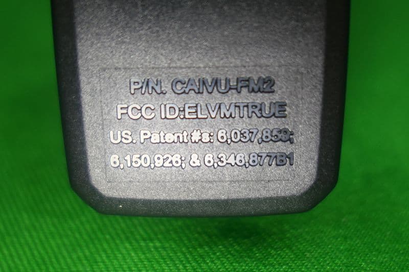
ELVMTRUE
May 29, 2021Transceiver
Equipment Class
DXX - Part 15 Low Power Communication Device Transmitter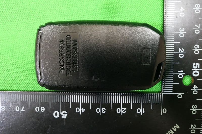
ELVMTUD
May 24, 2021Transmitter
Equipment Class
DXX - Part 15 Low Power Communication Device Transmitter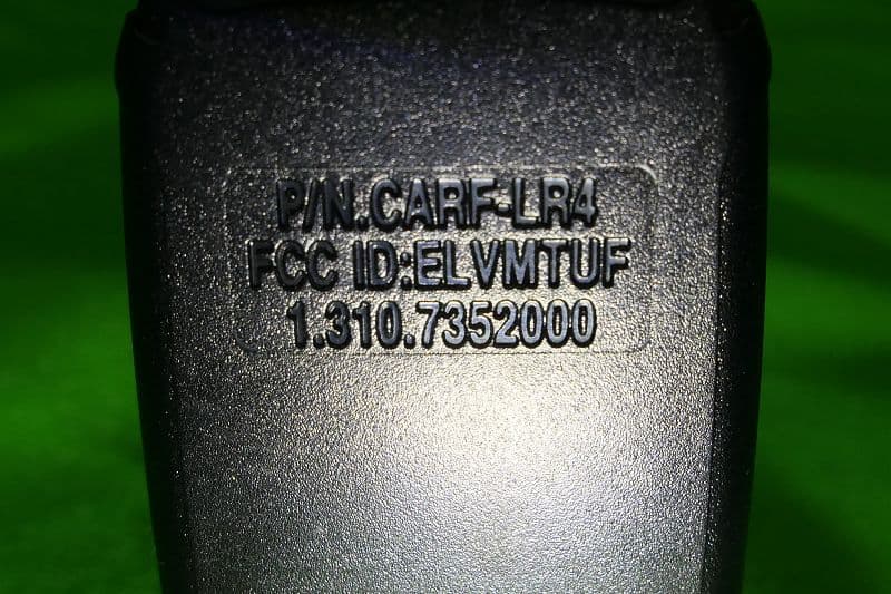
ELVMTUF
May 17, 2021Transmitter
Equipment Class
DXX - Part 15 Low Power Communication Device Transmitter