ELVATRIGTRANSCEIVER
Nutek Corporation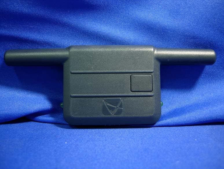
Click to zoom
Application Details
- Equipment Class
- DSS - Part 15 Spread Spectrum Transmitter
- Date of Grant
- Dec 13, 2010
- Application Purpose
- Original Equipment
- Date of Application
- Dec 08, 2010
- Equipment Note
- TRANSCEIVER
- Frequency Range
- 909.60000000 - 919.02400000
- Company
- Nutek Corporation
- Country
- Taiwan
Documents & Files
Document Text
Text extracted from the exhibit documents filed with the FCC. Open a document above to read the original.
Users Manual
128-8839 1 of 24 1 The selectable features can be set manually as explained below, or with the RF feature programmer.To set features using the RF programmer, follow the instructions packaged with the programmer.Factory default settings are indicated by bold text.Note : The method of manual override can either be selected to operate from the valet switch or operate as custom code. Be certain to place a check mark indicating the method used in the box located on the last page of the owner's manual.Note: Keyless Entry Models with no horn output will Flash the Parking Lights instead of chirp where chirp is indicated.Also, No data will be indicated if a feature is not available for a particular model. The unit will enter the feature but no se lection will be available. RF Programmable Feature Bank 1 Is For Transmitter Programming. See The Transmitter Programming Guide.RF Programmable Features Bank 2 Is Alarm Selectable Features:Feature Selection 1 Chirp 2 Chirps 3 Chirps 4 Chirps 5 Chirps 6 Chirps 1st DoorL/UL 1 Sec. 3.5 Sec. 1 Sec L, Dbl. U/L Dbl L, 1 Sec UL Dbl L, Dbl UL 1 S l/350 mS ul 2nd Accy Lock Auto Lock On Auto Lock Off 3rd Accy . UL Auto UL Dr. Auto UL All Auto UL Off ` 4th Headlights Not Available 5th Passive Locks Not Available 6th Pass/Act Arm Not Available 7th Siren/Horn Not Available 8th Horn Chirp 10 mS 16 mS 30 mS 40 mS 50 mS 9th O/R Method Not Available 10th 2 S tep U/L On Off 1 1th Chp Del Tx On Off 12th Vlot Sense/Hd Wire Not Available 13th Trigger Circuits Not Available 14th L/UL Poll Not Available 15th Aux Ch 5 Sel Pulse Push & Hold 10 Sec 20 Sec Latch On/Off Hold 3/S For O/P 16th Aux Ch 6 Sel Pulse Push & Hold 10 Sec 20 Sec Latch On/Off Hold 3/S For O/P 17th Aux Ch 7 Sel Pulse Push & Hold 10 Sec 20 Sec Latch On/Off Hold 3/S For O/P 18th Trigger Delay Not Available When using the RF programmer, enter the program mode as follows:1. Turn the ignition on.2. Press and release valet switch 3 times.3. Turn ignition off then on.4. Press and hold valet switch for 5 seconds.5. The siren and or lights chirp/flash 2 times, indicating access to RF feature program mode. Model SS6900 Installation Manual 128-8839 2 of 24 2 To program these selectable features; ActionSystem Response Turn ignition onNo response Press and release the valet switch 3 times1 chirp - LED 1 flash Within 3 seconds, turn ignition Off Then OnShort chirp, then long chirp This Action Accesses Feature Bank 2 Alarm Selectable Features FirstPress and release the valet switch 1 time1 chirp = 1 second door lock & unlock Press transmitter Lock button to change2 chirps = 3.5 second door lock & unlock Press transmitter Lock button to change3 chirps = 1 sec. lock, dbl 1 sec. unlock Press transmitter Lock button to change4 chirps = dbl 1 sec lock, 1 sec unlock Press transmitter Lock button to change5 chirps = dbl 1 sec lock, dbl 1 sec unlock Press transmitter Lock button to change6 chirps = 350 mS unlock. 1 sec lock or SecondPress and release the valet switch2 chirps = auto locks off Press transmitter Lock button to change1 chirp = auto locks on or ThirdPress and release the valet switch3 chirps = auto unlock off Press transmitter Lock button to change1 chirp = auto unlock drivers door only Press transmitter Lock button to change2 chirps = auto unlock all doors or FourthPress and release the valet switchNon Functional On This Unit or FifthPress and release the valet switchNon Functional On This Unit or SixthPress and release the valet switchNon Functional On This Unit or SeventhPress and release the valet switchNon Functional On This Unit or EighthPress and release the valet switch2 chirps = horn chirp output 16 mS Press transmitter Lock button to change3 chirps = horn chirp output 30 mS Press transmitter Lock button to change4 chirps = horn chirp output 40 mS Press transmitter Lock button to change5 chirps = horn chirp output 50 mS Press transmitter Lock button to change1 chirp = horn chirp output 10 mS or NinthPress and release the valet switchNon Functional On This Unit or TenthPress and release the valet switch2 chirps = 2 step unlock off Press transmitter Lock button to change1 chirp = 2 step unlock on or EleventhPress and release the valet switch2 chirps = chirp delete from transmitter inactive Press transmitter Lock button to change1 chirp = chirp delete from transmitter active or TwelfthPress and release the valet switchNon Functional On This Unit or ThirteenthPress and release the valet switchNon Functional On This Unit or FourteenthPress and release the valet switchNon Functional On This Unit or FifteenthPress and release the valet switch1 chirp = ch 5 pulsed output Press transmitter Lock button to change2 chirps = ch 5 output as long as button held Press transmitter Lock button to change3 chirps = ch 5-10 second output Press transmitter Lock button to change4 chirps = ch 5-20 second output Press transmitter Lock button to change5 chirps = ch 5 latch on/latch off output Press transmitter Lock button to change6 chirps = ch 5 hold 3 sec for pulsed output or SixteenthPress and release the valet switch1 chirp = ch 6 pulsed output Press transmitter Lock button to change2 chirps = ch 6 output as long as button held Press transmitter Lock button to change3 chirps = ch 6-10 second output Press transmitter Lock button to change4 chirps = ch 6-20 second output Press transmitter Lock button to change5 chirps = ch 6 latch on/latch off output Press transmitter Lock button to change6 chirps = ch 6 hold 3 sec for pulsed output or SeventeenthPress and release the valet switch1 chirp = ch 7 pulsed output Press transmitter Lock button to change2 chirps = ch 7 output as long as button held Press transmitter Lock button to change3 chirps = ch 7-10 second output Press transmitter Lock button to change4 chirps = ch 7-20 second output Press transmitter Lock button to change5 chirps = ch 7 latch on/latch off output Press transmitter Lock button to change6 chirps = ch 7 hold 3 sec for pulsed output or EighteenthPress and release the valet …
Text truncated - open the document above for the full version.
Cover Letter(s)
NUTEK CORPORATION FCC ID.: ELVATRIG No.167,Lane 235,Bauchiau Rd.,Shindian City,Taipei County,Taiwan Tel : 886 2 2912-3347 Federal Communications Commission Dec. 03 , 2010 Authorization and Evaluation Division ATTESTATION FCC ID: ELVATRIG Product: TRANSCEIVER Model: SS2PBL We don't provide any controls or software to allow operation outside the USA frequency band when we sell this product in USA.
Cover Letter(s)
RF_160, Issue 02 NUTEK CORPORATION Declaration of Authorization We Name: NUTEK CORPORATION Address: No.167,Lane 235,Bauchiau Rd.,Shindian City,Taipei County,Taiwan City: Taipei County . Country: Taiwan. . Declare that: Name Representative of agent: Gene Chang (1) Agent Company name: QuieTek Corp. Address: Fl.2, No.345, Xin-hu 2 nd Rd., Nei-hu District City: Taipei Country Taiwan is authorized to apply for Certification of the following product(s): Product description: TRANSCEIVER Type designation: SS2PBL Trademark: NUTEK on our behalf. Date: 2010/12/03 .. City: Taipei County .. Name: Charles Chen .. (2) Function: President Signature: Notes: (1): Required for FCC application (2): For FCC it must be the Grantee Code “owner” or the authorized agent.
External Photos
Report No.: 10B274R-RFUSP43V01 Page : 1 of 6 Version:1.0 Attachment 2 : EUT Detailed Photographs (1) EUT Photo (2) EUT Photo Report No.: 10B274R-RFUSP43V01 Page : 2 of 6 Version:1.0 (3) EUT Photo (4) EUT Photo
ID Label/Location Info
NUTEK CORPORATION FCC ID.: ELVATRIG No.167,Lane 235,Bauchiau Rd.,Shindian City,Taipei County,Taiwan Tel : 886 2 2912-3347 FCC ID Label The FCC ID and Doc Label will be placed on the equipment as shown in the photograph below.
ID Label/Location Info
NUTEK CORPORATION FCC ID.: ELVATRIG No.167,Lane 235,Bauchiau Rd.,Shindian City,Taipei County,Taiwan Tel : 886 2 2912-3347 FCC ID Label The FCC ID and Doc Label will be placed on the equipment as shown in the photograph below.
Internal Photos
Report No.: 10B274R-RFUSP43V01 Page : 3 of 6 Version:1.0 (5) EUT Photo (6) EUT Photo Report No.: 10B274R-RFUSP43V01 Page : 4 of 6 Version:1.0 (7) EUT Photo (8) EUT Photo Report No.: 10B274R-RFUSP43V01 Page : 5 of 6 Version:1.0 (9) EUT Photo (10) EUT Photo Report No.: 10B274R-RFUSP43V01 Page : 6 of 6 Version:1.0 (11) EUT Photo (12) EUT Photo
Operational Description
Report No. 10B274R-RFUSP43V01 Page: 7 of 53 1.2. Operational Description The EUT is a TRANSCEIVER with built-in 900MHz FHSS transceiver. The number of the channels is 25 in 909 - 919MHz. The device adapts the frequency hopping spread spectrum modulation. The antenna is monopole and solder on PCB and provides diversity function to improve the receiving function. The system receivers have input bandwidths that match the hopping channel bandwidths of their corresponding transmitters and shift frequencies in synchronization with the transmitted signals Frequency hopping spread spectrum systems are not required to employ all available hopping channels during each transmission. The transmitter is presented with a continuous data stream. In addition, a system employing short transmission bursts must comply with the definition of a frequency hopping system and must distribute its 25 channels and over the minimum number of hopping channels (25 channels). The incorporation of intelligence within a frequency hopping spread spectrum system that permits the system to recognize other users within the spectrum band so that it individually and independently chooses and adapts its hop sets to avoid hopping on occupied channels is permitted. The coordination of frequency hopping systems in any other manner for the express purpose of avoiding the simultaneous occupancy of individual hopping frequencies by multiple transmitters is not permitted. The frequency shift keying (FSK) transceiver intended for use in half-duplex, bidirectional RF links. The multi-channeled FSK transceiver is intended for UHF radio equipment. The transmitter consists of a PLL frequency synthesizer and power amplifier. The frequency synthesizer consists of a voltage-controlled oscillator (VCO), a crystal oscillator, dual modulus prescaler, programmable frequency dividers, and a phasedetector. The loop-filter is external for flexibility and can be a simple passive circuit. The output power of the power amplifier can be programmed to seven levels. A lock-detect circuit detects when the PLL is in lock. In receive mode, the PLL synthesizer generates the local oscillator (LO) signal. The N, M, and A values that give the LO frequency are stored in the N0, M0, and A0 registers. Another detail information please refer to spec of chipset.
Operational Description
1.Frequency Hopping Table CH0 0C CH4 00 CH8 03 CH120F CH1610 CH20 16 CH2411 CH1 08 CH5 05 CH9 09 CH1313 CH1712 CH21 15 CH2 06 CH6 01 CH10 04 CH140D CH180E CH22 18 CH3 02 CH7 07 CH11 0A CH150B CH1914 CH23 17 2.TX Every time transfer new package, it starts transmission from the next channel after last package’s end. 每次傳送新的封包會從上一次結束傳送的下一個channel開始傳送 3.RX Receiver receives signal by scanning. Every channel stops about 1.5ms. If it didn’t receive the correct synchronal data, it would jump to next channel for receiving. Receiver是以SCAN的方式做接收,每個channel大約停留1.5ms,若無接收到正確的同步資料,則 會跳到下一個channel重新接收
RF Exposure Info
Report No. 10B274R-RFUSP43V01 Page: 1 of 3 Version: 1.0 RF Exposure Evaluation declaration Product Name TRANSCEIVER Model No. SS2PBL FCC ID ELVATRIG Applicant NUTEK CORPORATION Address No.167,Lane 235,Bauchiau Rd.,Shindian City,Taipei County,Taiwan Date of Receipt Nov. 12, 2010 Date of Declaration Dec. 02, 2010 Report No. 10B274R-RFUSP43V01 The declaration results relate only to the samples calculated. The declaration shall not be reproduced except in full without the written approval of QuieTek Corporation. This report must not be used to claim product endorsement by NVLAP any agency of the U.S. Government Report No. 10B274R-RFUSP43V01 Page: 2 of 3 Version: 1.0 1. RF Exposure Evaluation 1.1. Limits According to FCC 1.1310: The criteria listed in the following table shall be used to evaluate the environment impact of human exposure to radio frequency (RF) radiation as specified in 1.1307(b) LIMITS FOR MAXIMUM PERMISSIBLE EXPOSURE (MPE) Frequency Range (MHz) Electric Field Strength (V/m) Magnetic Field Strength (A/m) Power Density (mW/cm 2 ) Average Time (Minutes) (A) Limits for Occupational/ Control Exposures 300-1500 -- -- F/300 6 1500-100,000 -- -- 5 6 (B) Limits for General Population/ Uncontrolled Exposures 300-1500 -- -- F/1500 6 1500-100,000 -- -- 1 30 F= Frequency in MHz Friis Formula Friis transmission formula: Pd = (Pout*G)/(4*pi*r 2 ) Where Pd = power density in mW/cm 2 Pout = output power to antenna in mW G = gain of antenna in linear scale Pi = 3.1416 R = distance between observation point and center of the radiator in cm Pd id the limit of MPE, 1 mW/cm 2 . If we know the maximum gain of the antenna and the total power input to the antenna, through the calculation, we will know the distance r where the MPE limit is reached. 1.2. Test Procedure Software provided by client enabled the EUT to transmit and receive data at lowest, middle and highest channel individually. The temperature and related humidity: 18°Cand 78% RH. Report No. 10B274R-RFUSP43V01 Page: 3 of 3 Version: 1.0 1.3. Test Result of RF Exposure Evaluation Product : TRANSCEIVER Test Item : RF Exposure Evaluation Test Site : No.3 OATS Antenna Gain Antenna Gain: The maximum Gain measured in fully anechoic chamber is 0dBi in logarithm scale. 1Mbps (FSK) –ANT A+ANT B Output Power Into Antenna & RF Exposure Evaluation Distance (0dBi): Channel Frequency (MHz) Output Power to Antenna (mW) Power Density at R = 20 cm (mW/cm2) 00 909.600 2.5704 0.000511 12 914.759 2.7669 0.000550 24 919.024 2.6792 0.000533
Test Report
Report No. 10B274R-RFUSP43V01 Page: 1 of 53 Test Report Product Name TRANSCEIVER Model No. SS2PBL FCC ID. ELVATRIG Applicant NUTEK CORPORATION Address No.167,Lane 235,Bauchiau Rd.,Shindian City,Taipei County,Taiwan Date of Receipt Nov. 12, 2010 Issued Date Dec. 02, 2010 Report No. 10B274R-RFUSP43V01 Report Version V1.0 The Test Results relate only to the samples tested. The test report shall not be reproduced except in full without the written approval of QuieTek Corporation. This report must not be used to claim product endorsement by NVLAP any agency of the U.S. Government Report No. 10B274R-RFUSP43V01 Page: 2 of 53 Test Report Certification Issued Date: Dec. 02, 2010 Report No.: 10B274R-RFUSP43V01 Product Name TRANSCEIVER Applicant NUTEK CORPORATION Address No.167,Lane 235,Bauchiau Rd.,Shindian City,Taipei County,Taiwan Manufacturer NUTEK CORPORATION Model No. SS2PBL FCC ID. ELVATRIG EUT Rated Voltage DC 12V EUT Test Voltage DC 12V by Battery Trade Name NUTEK Applicable Standard FCC CFR Title 47 Part 15 Subpart C: 2009 ANSI C63.4: 2003 Test Result Complied The Test Results relate only to the samples tested. The test report shall not be reproduced except in full without the written approval of QuieTek Corporation. This report must not be used to claim product endorsement by NVLAP any agency of the U.S. Government Documented By : (Senior Adm. Specialist / Leven Huang) Tested By : (Assistant Engineer / Sabrina Tsai) Approved By : (Manager / Vincent Lin ) Report No. 10B274R-RFUSP43V01 Page: 3 of 53 TABLE OF CONTENTS Description Page 1. GENERAL INFORMATION ...............................................................................................................5 1.1. EUT Description......................................................................................................................................5 1.2. Operational Description...........................................................................................................................7 1.3. Tested System Details..............................................................................................................................8 1.4. Configuration of Tested System ..............................................................................................................8 1.5. EUT Exercise Software ...........................................................................................................................8 1.6. Test Facility .............................................................................................................................................9 2. CONDUCTED EMISSION ................................................................................................................10 2.1. Test Equipment ......................................................................................................................................10 2.2. Test Setup ..............................................................................................................................................10 2.3. Limits.....................................................................................................................................................11 2.4. Test Procedure .......................................................................................................................................11 2.5. Uncertainty ............................................................................................................................................11 2.6. Test Result of Conducted Emission .......................................................................................................12 3. PEAK POWER OUTPUT ..................................................................................................................12 3.1. Test Equipment ......................................................................................................................................13 3.2. Test Setup ..............................................................................................................................................13 3.3. Limit .....................................................................................................................................................13 3.4. Test Procedure .......................................................................................................................................13 3.5. Uncertainty ............................................................................................................................................13 3.6. Test Result of Peak Power Output .........................................................................................................14 4. RADIATED EMISSION .....................................................................................................................17 4.1. Test Equipment ......................................................................................................................................17 4.2. Test Setup ..............................................................................................................................................17 4.3. Limits.....................................................................................................................................................18 4.4. Test Procedure .......................................................................................................................................19 4.5. Uncertainty ............................................................................................................................................19 4.6. Test Result of Radiated Emission ..........................................................................................................20 5. RF ANTENNA CONDUCTED TEST................................................................................................25 5.1…
Text truncated - open the document above for the full version.
Test Setup Photos
Report No.: 10B274R-RFUSP43V01 Page : 1 of 2 Attachment 1: EUT Test Setup Photographs Front View of Radiated Test Back View of Radiated Test Report No.: 10B274R-RFUSP43V01 Page : 2 of 2 Front View of Radiated Test (Horn) Back View of Radiated Test (Horn)
Contact Information
Applicant
Jason Wang
Technical Contact
QuieTek CorporationSabina Chen
[email protected]886-2-8601-3788
No. 5-22, Ruei-Shu Valley, Ruei-Ping Tsuen, · Taipei County · Taiwan
Test Firm
DEKRA Testing and Certification Co., Ltd.Sky Hsu
Technical Specifications
| # | Rule Parts | Frequency Range | Power Output |
|---|---|---|---|
| 1 | 15C | 909.6 MHz - 919.024 MHz | 3.00 mW |
Other Applications from Nutek Corporation
ELVATR6A
Sep 07, 2026Alarm module
Equipment Class
DTS - Digital Transmission SystemELVATR6B
Aug 19, 2026Vehicle Security and Remote Start System
Equipment Class
DSS - Part 15 Spread Spectrum TransmitterELVATRYA
Aug 13, 2024Transceiver
Equipment Class
DTS - Digital Transmission System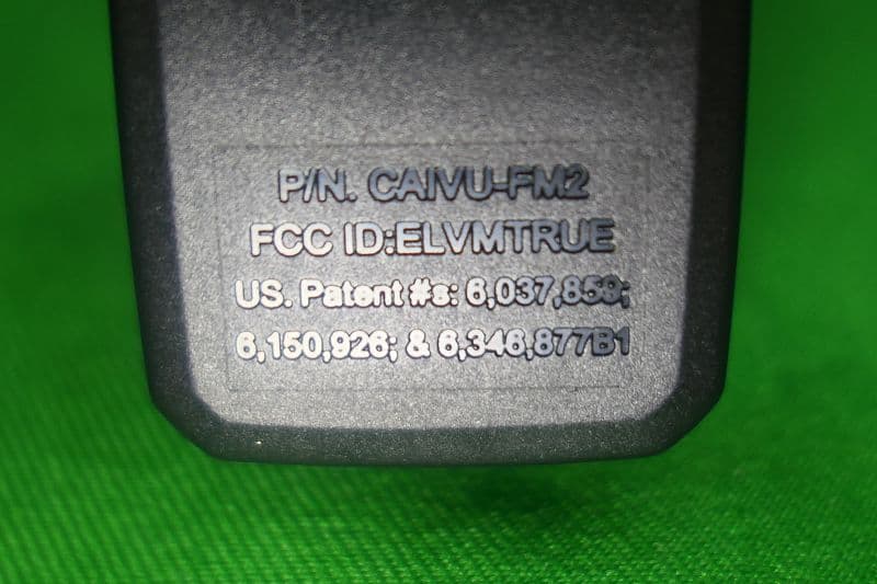
ELVMTRUE
May 29, 2021Transceiver
Equipment Class
DXX - Part 15 Low Power Communication Device Transmitter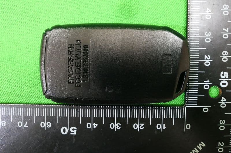
ELVMTUD
May 24, 2021Transmitter
Equipment Class
DXX - Part 15 Low Power Communication Device Transmitter