ELVATRJATransmitter
Nutek Corporation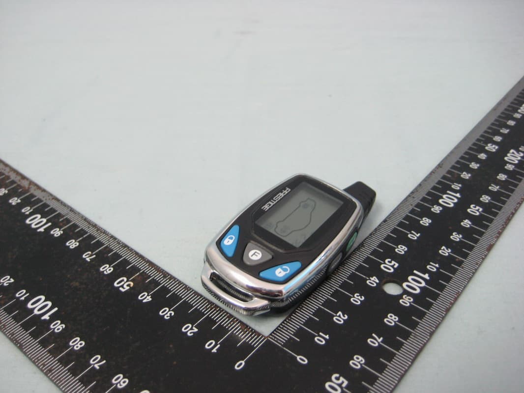
Click to zoom
Application Details
- Equipment Class
- DSC - Part 15 Security/Remote Control Transmitter
- Date of Grant
- Jun 27, 2010
- Application Purpose
- Original Equipment
- Date of Application
- Jun 27, 2010
- Equipment Note
- Transmitter
- Frequency Range
- 433.92000000 - 433.92000000
- Company
- Nutek Corporation
- Country
- Taiwan
Documents & Files
Document Text
Text extracted from the exhibit documents filed with the FCC. Open a document above to read the original.
Users Manual
128-8776 1 of 8 Your Alarm and or Remote Start unit has a configurable receiver that allows the transmitter to be programmed to operate the Lock Unlock functions with one transmitter button or with two transmitter buttons (separate Lock/ Unlock). In addition, the receiver also allows driver priority function. This driver priority function takes place when ever a particular transmitter is used to unlock the vehicle regardless of the selection of one button or two button operation. The following indicates the receiver programmable slots. 1 Lock/Unlock or Lock 2 Unlock if Programmed 3 Trunk Release & or Remote Start (Optional on some models) 4 Auxiliary Output 5 Auxiliary Output 6 Driver 1 Priority or Sperate Output 7 Driver 2 Priority or Separate Output Receiver channels 6 or 7 will accept the programming of transmitter channel 1 if used as the Lock/Unlock button, or Channel 2 when separate Lock Unlock buttons are programmed. In this way, whenever the transmit- ter is used to unlock the vehicle, channel 6 or 7, when programmed, will provide a pulsed ground output. This output can be connected to the driver priority function of the vehicle to reset preset user features. Please consult with your installation center technician to see if this feature is available in your vehicle. NOTE: A total of 4 transmitters may be programmed into any receiver channel. Force programming a transmitter, removing a transmitter, or reprioritizing a transmitter is covered later in this manual. Also, if you do not program a transmitter button into channel 2 which is the separate unlock/disarm channel, then whatever button is programmed into channel 1 will serve as both lock/arm & unlock/disarm. Note: The RED Button serves as a function button in combination with other buttons explained in your owners manual. This button may not be used to operate a receiver channel. NOTE: The Option Button is predetermined and programmed for access to Time Start, and Temperature Start & Check so it cannot be used for multiple button operation of any other feature. It will however operate for any single button programming. This transmitter is also capable of one button programming for certain model Audiovox Alarms. If your alarm is one of these models, then when step 3 is completed on the following page, you can turn the ignition switch off and Model 5BCR10P Programming Guide 128-8776 2 of 8 2 THIS PAGE LEFT BLANK INTENTIONALLY 128-8776 3 of 8 programming with the default button configurations for the first four chan- nels will be complete. TO ENTER THE PROGRAM MODE: 1. Turn the ignition switch to the “ON” position. 2. Within 10 seconds, Press and release the valet/program switch three times. (Siren emits 1 short chirp indicating channel 1 has been entered) 3. Within 10 Seconds, Press and hold the button of the first transmitter you wish to control the Lock&Arm feature of your security system until a long chirp is heard from the siren. (Repeat this for each transmitter you wish to operate the Lock/Arm feature). 4. Within 10 seconds, Press and release the valet program switch one time. (Siren emits 2 short chirps indicating channel 2 has been entered) 5. Within 10 Seconds, Press and hold any unused button(s) of the first transmitter you wish to control the Unlock/Disarm feature of your security system until a long chirp is heard from the siren. NOTE: This channel is used only if you desire separate control of the Lock/Unlock feature. If you wish to operate the Lock/Unlock features from a single button, move onto step 6 as whatever button is programmed into channel 1 will control both Lock & Arm/Unlock & Disarm. (Repeat this for each transmitter you wish to operate the Unlock/Disarm feature). 6. Within 10 seconds, Press and release the valet program switch one time. (Siren emits 3 short chirps indicating channel 3 has been entered) 7. Within 10 Seconds, Press and hold any unused button(s) of the first transmitter you wish to control Channel 3 output, (Trunk Release) until a long chirp is heard from the siren. (Repeat this for each transmitter you wish to operate the Channel 3 output (Trunk Release) 8. Within 10 seconds, Press and release the valet program switch one time. (Siren emits 4 short chirps indicating channel 4 has been entered) 9. Within 10 Seconds, Press and hold any unused button(s) of the first transmitter you wish to control Channel 4 output, (Auxiliary Output 1) until a long chirp is heard from the siren. (Repeat this for each transmitter you wish to operate the Channel 4 output) 10. Within 10 seconds, Press and release the valet program switch one time. (Siren emits 5 short chirps indicating channel 5 has been entered) 3 128-8776 4 of 8 11. Within 10 Seconds, Press and hold any unused button(s) of the first transmitter you wish to control Channel 5 output, (Auxiliary Output 2) until a long chirp is heard from the siren. (Repeat this for each transmitter you wish to operate the Channel 5 output) 12. Within 10 seconds, Press and release the valet program switch one time. (Siren emits 6 short chirps indicating channel 6 has been entered) 13. Within 10 Seconds, Press and hold the unlock button, (or any unused button(s)), of the first transmitter you wish to control Channel 6 output, (Driver Priority 1) until a long chirp is heard from the siren. (Repeat this for each transmitter you wish to operate the Channel 6 output, Driver Priority 1) 14. Within 10 seconds, Press and release the valet program switch one time. (Siren emits 7 short chirps indicating channel 7 has been entered) 15 .Within 10 Seconds, Press and hold the unlock button (or any unused button(s)) of the first transmitter you wish to control Channel 7 output, (Driver Priority 2) until a long chirp is heard from the siren. (Repeat this for each transmitter you wish to operate the Channel 7 output, Driver Priority 2) NOTE: Channels 6 and 7 can be used as a separate output to control a function other than driver priority. Simply programming any unused transmitte…
Text truncated - open the document above for the full version.
Cover Letter(s)
SCS-F18: Project and Product Certification Representative Authorization Letter Page 1 of 2 Rev 2.0 2206 Ringwood Avenue San Jose, CA 95131 Tel: 408-526-1188 Fax: 408-526-1088 Email: [email protected] Project and Product Certification Representative Authorization Letter Revision History Reason for Amendment (current / obsolete) From To Approved Date Initial Release (current) 1.0 1.0 Nov-14-2006 Revised wording (current) 1.0 2.0 Sept–25-2007 SCS-F18: Project and Product Certification Representative Authorization Letter Page 1 of 1 Rev 2.0 Jun. 24, 2010 To: SIEMIC, INC. 2206 Ringwood Avenue, San Jose, CA 95131 USA Dear Sir/Madam, Re: Project and Product Certification Representative Authorization Letter We, Nutek Corporation hereby authorize SIEMIC, INC. to act as a Certification Body for certifying for the following project(s): Product: Transmitter, Model No.: 5BCR10P, FCC ID: ELVATRJA We affirm that between SIEMIC and Nutek Corporation, any difference in understanding, including test plan, measurement methods, applicable standards and relevant procedures and processes have been resolved prior to commencement of testing activities. Sincerely, Charles Chen / President Nutek Corporation Tel: +886 2 2918 9478 Fax: +886 2 2917 9069 E-mail: [email protected]
Cover Letter(s)
SCS-F19: Confidentiality Request Letter Rev 1.0 Nov 14, 2006 Confidentiality Request Letter Revision History Reason for Amendment (current / obsolete) From To Approved Date Initial Release (current) 1.0 1.0 Nov-14-2006 SCS-F19: Confidentiality Request Letter Rev 1.0 Nov 14, 2006 Jun.24, 2010 To: Federal Communications Commission Authorization and Evaluation Division Confidentiality Request regarding application for certification of FCC ID: ELVATRJA We hereby request confidential treatment of information accompanying this application as outlined below: • Block Diagram • Schematics • Operational Description The above materials contain trade secrets and proprietary information not customarily released to the public. The public disclosure of these materials may be harmful to the applicant and provide unjustified benefits to its competitors. The applicant understands that pursuant to Section 0.457 of the Rules, disclosure of this application and all accompanying documentation will not be made before the date of the Grant for this application. Sincerely, Charles Chen / President Nutek Corporation Tel: +886 2 2918 9478 Fax: +886 2 2917 9069 E-mail: [email protected]
External Photos
Report No.:10A060902FR FCC ID: ELVATRJA Page 22 of 25 Interocean EMC Technology Corp. Test Report 7 Photographs of EUT Front View of EUT Rear View of EUT
ID Label/Location Info
O P T I O N BODY MATERIAL : ABS+PC MT-11010 0.2 Eason YYS Victor P A R T N O . 5 B C R 1 0 P 8 0 0 - 2 2 5 - 6 0 7 4 F C C I D : E L V A T R J A X X m o b i l e . a u d i o v o x . c o m
Internal Photos
Report No.:10A060902FR FCC ID: ELVATRJA Page 23 of 25 Interocean EMC Technology Corp. Test Report Inner View of EUT Antenna Location Report No.:10A060902FR FCC ID: ELVATRJA Page 24 of 25 Interocean EMC Technology Corp. Test Report Component View of PCB Board-1 Solder View of PCB Board-1 Report No.:10A060902FR FCC ID: ELVATRJA Page 25 of 25 Interocean EMC Technology Corp. Test Report Component View of PCB Board-2 Solder View of PCB Board-2
Test Report
Report No.:10A060902FR FCC ID: ELVATRJA Page 1 of 25 Interocean EMC Technology Corp. Test Report CFR 47 FCC Part 15.231 TEST REPORT Product: Transmitter Trade Name: N/A Model Number: 5BCR10P FCC ID: ELVATRJA Prepared for Nutek Corporation NO.167, Lane 235, Bauchiau Rd., Shindian City, Taipei County 23145, Taiwan TEL.: +886 2 2918 9478 FAX.: +886 2 2917 9069 Prepared by Interocean EMC Technology Corp. 244 No.5-2, Lin 1, Tin-Fu Tsun, Lin-Kou Hsiang, Taipei County, Taiwan, R.O.C. TEL.: +886 2 2600 6861 FAX.: +886 2 2600 6859 Remark: The test report consists of 25 pages in total. It shall not be reproduced except in full, without the written approval of IETC. This document may be altered or revised by IETC only, and shall be noted in the revision section of the document. The test results in the report only to the tested sample. Report No.:10A060902FR FCC ID: ELVATRJA Page 3 of 25 Interocean EMC Technology Corp. Test Report Table of Contents 1 Summary of Measurement 4 2 General Information 5 2.1 Description of Equipment Under Test 5 2.2 Details of tested peripheral equipment 6 2.3 Test Facility 7 3 Test specifications 8 3.1 Test standard 8 3.2 Operation mode 8 3.3 Test Equipment 9 4 Radiated emission test 10 4.1 Limits 10 4.2 Calculation of Average Factor 11 4.3 Configuration of Measurement 16 4.4 Test Procedure 16 4.5 Test Result 16 5 Emission bandwidth 19 5.1 Limits 19 5.2 Test Result 19 6 Photographs of Test 21 6.1 Radiated Emission Measurement 21 7 Photographs of EUT 22 Report No.:10A060902FR FCC ID: ELVATRJA Page 4 of 25 Interocean EMC Technology Corp. Test Report 1 Summary of Measurement Report Clause Test Parameter Reference Document CFR47 Part15 Results 4 Radiated Emission §15.231(b), 15.209 Pass 5 Emission bandwidth §15.231(c) Pass Report No.:10A060902FR FCC ID: ELVATRJA Page 5 of 25 Interocean EMC Technology Corp. Test Report 2 General Information 2.1 Description of Equipment Under Test Product : Transmitter Model Number : 5BCR10P Applicant : Nutek Corporation NO.167, Lane 235, Bauchiau Rd., Shindian City, Taipei County 23145, Taiwan Manufacturer : Nutek Corporation NO. 167, Lane 235, Bauchiau Rd., Shindian City, Taipei County 23145, Taiwan Power Supply : 1.5Vdc Battery Operating Frequency : 433.92MHz Channel Number : 1 channel Type of Modulation : ASK Antenna description : This device uses Spring antenna. The antenna is integral to the device, thereby meeting the requirement of FCC 15.203. Date of Receipt Sample : Jun. 09, 2010 Date of Test : Jun. 09 ~ 23, 2010 Additional Description : 1) The Model Number “5BCR10P” is representative selected in the test and included in this report. 2) For more detail specification about EUT, please refer to the user’s manual. Report No.:10A060902FR FCC ID: ELVATRJA Page 6 of 25 Interocean EMC Technology Corp. Test Report 2.2 Details of tested peripheral equipment N/A Report No.:10A060902FR FCC ID: ELVATRJA Page 7 of 25 Interocean EMC Technology Corp. Test Report 2.3 Test Facility Site Description : OATS 2 Name of Firm : Interocean EMC Technology Corp. Company web : http://www.ietc.com.tw Site 1, 2 Location : No.5-2, Lin 1, Tin-Fu Tsun, Lin-Kou Hsiang, Taipei County, Taiwan, R.O.C. Site 3, 4 Location : No. 12, Ruei-Shu Valley, Ruei-Ping Tsun, Lin-Kou Hsiang, Taipei County, Taiwan, R.O.C. Site Filing : z Federal Communication Commissions – USA Registration No.: 96399 (OATS 1 & 2) Registration No.: 518958 (OATS 3 & 4) Designation No.: TW1020 z Voluntary Control Council for Interference by Information Technology Equipment (VCCI) – Japan Member No.: 1349 Registration No. (Conducted Room): C-1094 Registration No. (Conducted Room): T-1562 Registration No. (OATS 1): R-1040 Registration No. (OATS 2): R-1041 z Industry Canada (IC) OUR FILE: 46405-4437 Submission: 130946 Registration No. (OATS 1): 4437A-1 Registration No. (OATS 2): 4437A-2 Registration No. (OATS 3): 4437A-3 Registration No. (OATS 4): 4437A-4 Site Accreditation : z Bureau of Standards and Metrology and Inspection (BSMI) – Taiwan, R.O.C. Accreditation No.: SL2-IN-E-0026 for CNS13438 / CISPR22 SL2-R1-E-0026 for CNS13439 / CISPR13 SL2-R2-E-0026 for CNS13439 / CISPR13 SL2-A1-E-0026 for CNS13783-1 / CISPR14-1 SL2-L1-E-0026 for CNS 14115 / CISPR 15 z Taiwan Accreditation Foundation (TAF) Accrditation No.: 1113 z TüV NORD Certificate No: TNTW0801R-02 Report No.:10A060902FR FCC ID: ELVATRJA Page 8 of 25 Interocean EMC Technology Corp. Test Report 3 Test specifications 3.1 Test standard The EUT was performed according to FCC Part 15 Subpart C Section 15.231 procedure and setup followed by ANSI C63.4, 2003 requirements. 3.2 Operation mode By preliminary testing and verifying three axis (X, Y and Z) position of EUT transmitted status, it was found that “X axis” position was the worst, then the final test was executed the worst condition and test data were recorded in this report The EUT was operated in continuous transmission mode during all of the tests. X axis mode Y axis mode Z axis mode Report No.:10A060902FR FCC ID: ELVATRJA Page 9 of 25 Interocean EMC Technology Corp. Test Report 3.3 Test Equipment Instrument ManufacturerModel Serial No. Next Cal. Date Spectrum Analyzer R&S FSP30 100002 2010/12/08 Spectrum Analyzer R&S FSP40 100478 2011/04/20 Preamplifier Agilent 8449B 3008A01434 2011/04/20 Preamplifier Agilent 83050A 3950A00225 2010/08/10 Preamplifier SCHAFFNER CA30100 2 2010/11/03 Horn Antenna Schwarzbeck BBHA 9120 9120D-583 2011/02/09 Wide Bandwidth Sensor Anritsu MA2491A 728133 2010/11/13 Power Meter Anritsu ML2495A 736010 2010/11/13 Temp & Humidity chamber GIAN FORCE GTH-150-40-2P-U MAA0305-012 2011/05/07 Note: The above equipments are within the valid calibration period. Report No.:10A060902FR FCC ID: ELVATRJA Page 10 of 25 Interocean EMC Technology Corp. Test Report 4 Radiated emission test 4.1 Limits According to FCC 15.231(b) requirement: In addition to the provisions of §15.205, the field strength of emissions from intentional radiator operated under this section shall not exceed the foll…
Text truncated - open the document above for the full version.
Test Setup Photos
Report No.:10A060902FR FCC ID: ELVATRJA Page 21 of 25 Interocean EMC Technology Corp. Test Report 6 Photographs of Test 6.1 Radiated Emission Measurement Front View Rear View
Contact Information
Applicant
Jason Wang
Test Firm
Interocean EMC Technology Corp.Mike Huang
Technical Specifications
| # | Rule Parts | Frequency Range | Power Output |
|---|---|---|---|
| 1 | 15.231 | 433.92 MHz - 433.92 MHz | - |
Other Applications from Nutek Corporation
ELVATR6A
Sep 07, 2026Alarm module
Equipment Class
DTS - Digital Transmission SystemELVATR6B
Aug 19, 2026Vehicle Security and Remote Start System
Equipment Class
DSS - Part 15 Spread Spectrum TransmitterELVATRYA
Aug 13, 2024Transceiver
Equipment Class
DTS - Digital Transmission System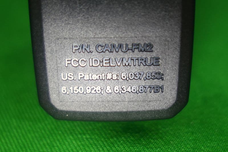
ELVMTRUE
May 29, 2021Transceiver
Equipment Class
DXX - Part 15 Low Power Communication Device Transmitter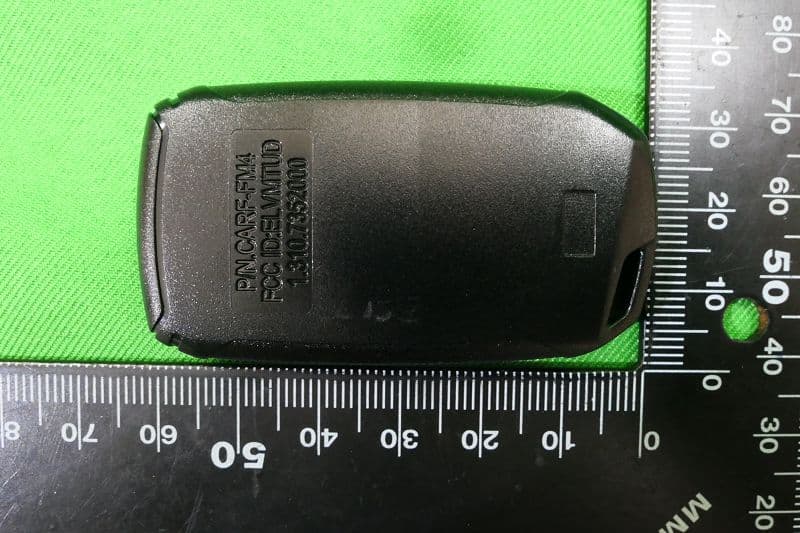
ELVMTUD
May 24, 2021Transmitter
Equipment Class
DXX - Part 15 Low Power Communication Device Transmitter