ELVATRKBTransmitter
Nutek Corporation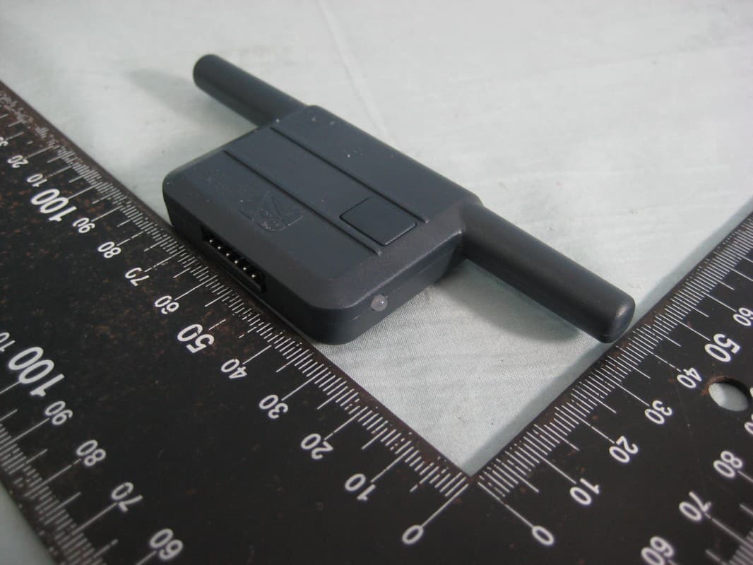
Click to zoom
Application Details
- Equipment Class
- DSS - Part 15 Spread Spectrum Transmitter
- Date of Grant
- May 10, 2011
- Application Purpose
- Original Equipment
- Date of Application
- May 10, 2011
- Equipment Note
- Transmitter
- Frequency Range
- 909.50000000 - 919.02400000
- Company
- Nutek Corporation
- Country
- Taiwan
Documents & Files
Document Text
Text extracted from the exhibit documents filed with the FCC. Open a document above to read the original.
Users Manual
128-8843a 1 of 28 1 Model SS9000 Installation Manual SELECT ABLE FEA TURES The selectable features can be set manually as explained below, or with the RF feature programmer.To set features using the RF programmer, follow the instructions packaged with the programmer.Factory default settings are indicated by bold text. Note : The method of manual override can either be selected to operate from the valet switch or operate as custom code. Be certain to place a check mark indicating the method used in the box located on the last page of the owner's manual.NOTE: Keyless Entry Models with no horn output will Flash the Parking Lights instead of chirp where chirp is indicated.Also, No data will be indicated if a feature is not available for a particular model. The unit will enter the feature but no s election will be available. RF Programmable Feature Bank 1 Is For Transmitter Programming See Transmitter Programming Guide.RF Programmable Features Bank 2 Is Alarm Selectable Features:Feature Selection 1 Chirp 2 Chirps 3 Chirps 4 Chirps 5 Chirps 6 Chirps 1st DoorL/UL 1 Sec. 3.5 Sec. 1 Sec L, Dbl. U/L Dbl L, 1 Sec UL Dbl L, Dbl UL 1 S l/350mS ul 2nd Accy Lock Auto Lock On Auto Lock Off 3rd Accy . UL Auto UL Dr. Auto UL All Auto UL Off 4th Headlights On Arm On Disarm On Both Off 5th Passive Locks Passive Active 6th Pass/Act Arm Passive Arm Active Arm 7th Siren/Horn Siren/Horn Siren Only Horn Only 8th Horn Chirp 10mS 16mS 30mS 40mS 50mS 9th O/R Method Custom Code Valet 10th 2 S tep U/L On Off 1 1th Chp Del Tx On Off 12th V olt s/HdW ire Not Available 13th Trigger Circuits All On Doors Off Hood/Trunk Off All Off 14th L/UL Poll Not Available 15th Aux Ch 5 Sel Pulse Push & Hold 10 Sec 20 Sec Latch On/Off Hold 3/S For O/P 16th Aux Ch 6 Sel Pulse Push & Hold 10 Sec 20 Sec Latch On/Off Hold 3/S For O/P 17th Aux Ch 7 Sel Pulse Push & Hold 10 Sec 20 Sec Latch On/Off Hold 3/S For O/P 18th Trigger Delay Not Available When using the RF programmer, enter the program mode as follows:Turn the ignition onPress and release valet switch 3 timesturn ignition off then onPress and hold valet switch for 5 secondsSiren chirps 2 times indicating access to RF feature program mode. Rev a Modify FCC Statement 5/06/11 128-8843a 2 of 28 2 To program these selectable features; ActionSystem Response Turn ignition onNo response Press and release the valet switch 3 times1 Chirp - LED 1 flash Within 3 seconds, turn ignition Off Then OnShort chirp, then long chirp This Action Accesses Feature Bank 2 AlarmSelectable Features FirstPress and release the valet switch 1 time1 chirp = 1 second door lock & unlock Press transmitter Lock button to change2 chirps = 3.5 second door lock & Unlock Press transmitter Lock button to change3 chirps = 1 sec. lock, dbl 1 sec. unlock Press transmitter Lock button to change4 chirps = dbl 1 sec lock, 1 sec unlock Press transmitter Lock button to change5 chirps = dbl 1 sec lock, dbl 1 sec unlock Press transmitter Lock button to change6 chirps = 350mS unlock. 1 sec lock or SecondPress and release the valet switch2 chirps = auto locks off Press transmitter Lock button to change1 chirp = auto locks on or ThirdPress and release the valet switch3 chirps = auto unlock off Press transmitter Lock button to change1 chirp = auto unlock drivers door only Press transmitter Lock button to change2 chirps = auto unlock all doors or FourthPress and release the valet switch3 chirps = headlight output when arming and disarming Press transmitter Lock button to change4 chirps = headlight output off Press transmitter Lock button to change1 chirp = headlight output when arming Press transmitter Lock button to change2 chirps = headlight output when disarming or FifthPress and release the valet switch2 chirps = active locks Press transmitter Lock button to change1 chirp = passive locks or SixthPress and release the valet switch2 chirps = active arming Press transmitter Lock button to change1 chirp = passive arming or SeventhPress and release the valet switch1 chirp = siren and horn output Press transmitter Lock button to change2 chirps = siren output only Press transmitter Lock button to change3 chirps = horn output only or EighthPress and release the valet switch2 chirps = horn chirp output 16mS Press transmitter Lock button to change3 chirps = horn chirp output 30mS Press transmitter Lock button to change4 chirps = horn chirp output 40mS Press transmitter Lock button to change5 chirps = horn chirp output 50mS Press transmitter Lock button to change1 chirp = horn chirp output 10 mS or NinthPress and release the valet switch2 chirps = valet switch override operation Press transmitter Lock button to change1 chirp = custom code override operation or TenthPress and release the valet switch2 chirps = 2 step unlock off Press transmitter Lock button to change1 chirp = 2 step unlock on or EleventhPress and release the valet switch2 chirps = chirp delete from transmitter inactive Press transmitter Lock button to change1 chirp = chirp delete from transmitter active or TwelfthPress and release the valet switchNon Functional On This Unit or ThirteenthPress and release the valet switch1 chirp - all on Press transmitter lock button to change2 chirps = doors off Press transmitter lock button to change3 chirps = hood & trunk off Press transmitter lock button to change4 chirps = all off or FourteenthPress and release the valet switchNon Functional On This Unit or FifteenthPress and release the valet switch1 chirp = ch 5 pulsed output Press transmitter Lock button to change2 chirps = ch 5 output as long as button held Press transmitter Lock button to change3 chirps = ch 5-10 second output Press transmitter Lock button to change4 chirps = ch 5-20 second output Press transmitter Lock button to change5 chirps =ch 5 latch on/latch off output Press transmitter Lock button to change6 chirps = ch 5 hold 3 sec for pulsed output or SixteenthPress and release the valet switch1 chirp = ch 6 pulsed output Press transmitter Lock button to change2 chirps = ch 6…
Text truncated - open the document above for the full version.
Cover Letter(s)
SCS-F18: Project and Product Certification Representative Authorization Letter Page 1 of 2 Rev 2.0 2206 Ringwood Avenue San Jose, CA 95131 Tel: 408-526-1188 Fax: 408-526-1088 Email: [email protected] Project and Product Certification Representative Authorization Letter Revision History Reason for Amendment (current / obsolete) From To Approved Date Initial Release (current) 1.0 1.0 Nov-14-2006 Revised wording (current) 1.0 2.0 Sept–25-2007 SCS-F18: Project and Product Certification Representative Authorization Letter Page 2 of 2 Rev 2.0 Apr. 29, 2011 To: SIEMIC, INC. 2206 Ringwood Avenue, San Jose, CA 95131 USA Dear Sir/Madam, Re: Project and Product Certification Representative Authorization Letter We, Nutek Corporation hereby authorize SIEMIC, INC. to act as a Certification Body for certifying for the following project(s): Product: Transmitter, Model No.: SS2PBL; REC-2N900, FCC ID: ELVATRKB We affirm that between SIEMIC and Nutek Corporation, any difference in understanding, including test plan, measurement methods, applicable standards and relevant procedures and processes have been resolved prior to commencement of testing activities. Sincerely, Charles Chen / President Nutek Corporation Tel: +886 2 2918 9478 Fax: +886 2 2917 9069 E-mail: [email protected]
Cover Letter(s)
SCS-F19: Confidentiality Request Letter Rev 1.0 Nov 14, 2006 Confidentiality Request Letter Revision History Reason for Amendment (current / obsolete) From To Approved Date Initial Release (current) 1.0 1.0 Nov-14-2006 SCS-F19: Confidentiality Request Letter Rev 1.0 Nov 14, 2006 Apr. 29, 2011 To: Federal Communications Commission Authorization and Evaluation Division Confidentiality Request regarding application for certification of FCC ID: ELVATRKB We hereby request confidential treatment of information accompanying this application as outlined below: • Block Diagram • Schematics • Operational Description The above materials contain trade secrets and proprietary information not customarily released to the public. The public disclosure of these materials may be harmful to the applicant and provide unjustified benefits to its competitors. The applicant understands that pursuant to Section 0.457 of the Rules, disclosure of this application and all accompanying documentation will not be made before the date of the Grant for this application. Sincerely, Charles Chen / President Nutek Corporation Tel: +886 2 2918 9478 Fax: +886 2 2917 9069 E-mail: [email protected]
External Photos
Report No.: 11A033003FR FCC ID:ELVATRKB Page 39 of 46 Interocean EMC Technology Corp. Test Report 11 Photographs of EUT 11.1 Model No.: SS2PBL Front View of EUT Rear View of EUT
ID Label/Location Info
Eason YYS Victor MT-10010 BODY MATERIAL : HIGH HEAT ABS+UV MTF02008x2 DARK GRAY(#432C) 0.2 A ± C ±± B FCC ID:ELVATRKB 800-225-6074 PART NO.SS2PBL FCC ID:ELVATRIG
Internal Photos
Report No.: 11A033003FR FCC ID:ELVATRKB Page 40 of 46 Interocean EMC Technology Corp. Test Report Inner View of EUT Antenna Location Report No.: 11A033003FR FCC ID:ELVATRKB Page 41 of 46 Interocean EMC Technology Corp. Test Report Front View of Main Board -1 Front View of Main Board -2 Report No.: 11A033003FR FCC ID:ELVATRKB Page 42 of 46 Interocean EMC Technology Corp. Test Report Rear View of Main Board Report No.: 11A033003FR FCC ID:ELVATRKB Page 43 of 46 Interocean EMC Technology Corp. Test Report 11.2 Model No.: REC-2N900 Front View of EUT Rear View of EUT Report No.: 11A033003FR FCC ID:ELVATRKB Page 44 of 46 Interocean EMC Technology Corp. Test Report Inner View of EUT Report No.: 11A033003FR FCC ID:ELVATRKB Page 45 of 46 Interocean EMC Technology Corp. Test Report Front View of Main Board -1 Front View of Main Board -2 Report No.: 11A033003FR FCC ID:ELVATRKB Page 46 of 46 Interocean EMC Technology Corp. Test Report Rear View of Main Board
RF Exposure Info
FCC ID:ELVATRKB Report No.:11A033003FR Page 1 of 5 Maximum Permissible Exposure (MPE) Evaluation Report E.U.T.: Transmitter Model Number: SS2PBL; REC-2N900 According: FCC Guidelines for Human Exposure IEEE C95.1 The test report consists of 5 pages in total. It shall not be reproduced except in full, without the written approval of IETC. This document may be altered or revised by IETC only, and shall be noted in the revision section of the document. The test results in the report only to the tested sample. Report Issued: 2011/05/04 Project Engineer: Approved: Elli Chang Jerry Liu Applicant: Nutek Corporation Address: NO.167, LANE235, BAUCHIAU RD., XINDIAN DISTRICT , NEW TAIPEI CITY 231, TAIWAN Issued By: Interocean EMC Technology Corp. LAB Location: No. 5-2, Lin 1, Tin-Fu, Lin-Kou Dist., New Taipei City, Taiwan 244, R.O.C. FCC ID:ELVATRKB Report No.:11A033003FR Page 2 of 5 Table of Contents 1 Introduction 4 2 Classification 4 3 RF Exposure Limit 4 4 Friis Formula 5 5 EUT Operating condition 5 6 Test Results 5 FCC ID:ELVATRKB Report No.:11A033003FR Page 3 of 5 Summary of Tests Local Control Node Module Model: SS2PBL; REC-2N900 Test Reference Results MPE Evaluation FCC Guidelines for Human Exposure IEEE C95.1 Pass FCC ID:ELVATRKB Report No.:11A033003FR Page 4 of 5 RF Exposure Measurement (Fixed use Device) 1 Introduction The manufacturer whose product is working in this frequency band is obligatory to prove the harmfulness of his product. In this document, we try to prove the safety of radiation harmfulness to the human body for our product. The limit for Maximum Permissible Exposure (MPE) specified in FCC 1.1310 is followed. The Gain of the antenna used in this product is measured in a Fully Anechoic Chamber (FAC), and the maximum total power input to the antenna is measured. Through the Friis transmission formula and the maximum gain of the antenna, we can calculate the distance, away from the product, where the limit of MPE is reached. 2 Classification The antenna of the product, under normal use condition, is at least 20cm away from the body of the user. Warning statement for keeping 20cm separation distance and the prohibition of operating next to a person has been printed on the user’s manual. So, this product is classified as the Fixed use Device 3 RF Exposure Limit According to FCC 1.1310: The criteria listed in the following table shall be used to evaluate the environmental impact of human exposure to radio-frequency (RF) radiation as specified in 1.1307(b). LIMITS FOR MAXIMUM PERMISSIBLE EXPOSURE (MPE) Frequency Range (MHz) Electric Field Strength (V/m) Magnetic Field Strength (A/m) Power Density (mW/cm 2 ) Average Time (minutes) (A) Limits For Occupational / Control Exposures 30-300 61.4 0.163 1.0 6 300-1500 ... ... F/300 6 1500-100,000 ... ... 5 6 (B)Limits For General Population / Uncontrolled Exposure 30-300 27.5 0.073 0.2 30 300-1500 ... ... F/1500 30 1500-100,000 ... ... 1.0 30 F = Frequency in MHz FCC ID:ELVATRKB Report No.:11A033003FR Page 5 of 5 4 Friis Formula Friis transmission formula: Pd = (Pout*G) / (4*pi*r 2 ) where Pd = power density in mW/cm2 Pout = output power to antenna in mW G = gain of antenna in linear scale Pi = 3.1416 R = distance between observation point and center of the radiator in cm Pd is the limit of MPE, 1 mW/cm2. If we know the maximum Gain of the antenna and the total power input to the antenna, through the calculation, we will know the distance r where the MPE limit is reached. 5 EUT Operating condition The software provided by Manufacturer enabled the EUT to transmit and receive data at lowest, middle and highest channel individually. 6 Test Results Frequency (MHz) Maximum Antenna gain (numeric) Output power To antenna (mW) Power density (mW/cm 2 ) Limit of Power density (mW/cm 2 ) 909.5 to 919.024MHz 1 12.735 0.00253 0.6 The minimum allowable distance is very close to the enclosure of the antenna. So, the user has no need to worry about the harmfulness of radiation. But it is recommended to always keep, at least, 20cm separation distance with the antenna.
Test Report
Report No.: 11A033003FR FCC ID:ELVATRKB Page 1 of 46 Interocean EMC Technology Corp. Test Report CFR 47 FCC Part 15.247 TEST REPORT Product: Transmitter Trade Name: N/A Model Number: SS2PBL; REC-2N900 FCC ID: ELVATRKB Prepared for Nutek Corporation NO. 167, LANE 235, BAUCHIAU RD., XINDIAN DISTRICT, NEW TAIPEI CITY 231, TAIWAN TEL.: +886 2 2918 9478 FAX.: +886 2 2917 9069 Prepared by Interocean EMC Technology Corp. 244 No.5-2, Lin 1, Tin-Fu Tsun, Lin-Kou Hsiang, Taipei County, Taiwan, R.O.C. TEL.: +886 2 2600 6861 FAX.: +886 2 2600 6859 Remark: The test report consists of 46 pages in total. It shall not be reproduced except in full, without the written approval of IETC. This document may be altered or revised by IETC only, and shall be noted in the revision section of the document. The test results in the report only to the tested sample. Report No.: 11A033003FR FCC ID:ELVATRKB Page 2 of 46 Interocean EMC Technology Corp. Test Report Table of Contents 1 General Information 5 1.1 Description of Equipment Under Test 5 1.2 Table for Carrier Frequencies 6 1.3 Details of Tested Supporting System 6 1.4 Test Facility 7 1.5 Test Equipment 8 1.6 Summary of Measurement 9 1.7 Justification 10 2 Test specifications 11 2.1 Test standard 11 2.2 Operation mode 11 3 20dB Bandwidth test 12 3.1 Limit 12 3.2 Configuration of Measurement 12 3.3 Test Procedure 12 3.4 Test Result 12 4 Carrier Frequency Separation test 15 4.1 Limit 15 4.2 Configuration of Measurement 15 4.3 Test Procedure 15 4.4 Test Result 15 5 Number of hopping frequencies test 17 5.1 Configuration of Measurement 17 5.2 Test Procedure 17 5.3 Test Result 17 6 Time of Occupancy (dwell time) test 19 6.1 Limit 19 6.2 Configuration of Measurement 19 6.3 Test Procedure 19 6.4 Test Result 19 7 Maximum Output Power test 21 7.1 Limit 21 7.2 Configuration of Measurement 21 7.3 Test Procedure 21 7.4 Test Result 21 Report No.: 11A033003FR FCC ID:ELVATRKB Page 3 of 46 Interocean EMC Technology Corp. Test Report 8 RF Conducted spurious emission 25 8.1 Limit 25 8.2 Configuration of Measurement 25 8.3 Test Procedure 25 8.4 Test Result 25 9 RF Radiated spurious emission test 31 9.1 Limit 31 9.2 Configuration of Measurement 31 9.3 Test Procedure 32 9.4 Test Result 32 10 Photographs of Test 37 10.1 Radiated Emission Measurement 37 11 Photographs of EUT 39 11.1 Model No.: SS2PBL 39 11.2 Model No.: REC-2N900 43 Report No.: 11A033003FR FCC ID:ELVATRKB Page 4 of 46 Interocean EMC Technology Corp. Test Report Statement of Compliance Applicant: Nutek Corporation Manufacturer: Nutek Corporation Product: Transmitter Model No.: SS2PBL; REC-2N900 Tested Power Supply: DC12V from battery Date of Final Test: Apr. 20, 2011 Revision of Report: Rev. 00 Configuration of Measurements and Standards Used: FCC Rules and Regulations Part 15 Subpart C I HEREBY CERTIFY THAT: The data shown in this report were made in accordance with the procedures given in ANSI C63.4, and the energy emitted by the device was founded to be within the limits applicable. I assume full responsibility for accuracy and completeness of these data. Note: 1. The result of the testing report relate only to the item tested. 2. The testing report shall not be reproduced expect in full, without the written approval of IETC Report Issued: 2011/04/29 Project Engineer: Approved: Elli Chang Jerry Liu Report No.: 11A033003FR FCC ID:ELVATRKB Page 5 of 46 Interocean EMC Technology Corp. Test Report 1 General Information 1.1 Description of Equipment Under Test Product : Transmitter Model Number : SS2PBL; REC-2N900 Applicant : Nutek Corporation NO.167, Lane 235, Bauchiau Rd., Shindian City, Taipei County 23145, Taiwan Manufacturer : Nutek Corporation NO.167, Lane 235, Bauchiau Rd., Shindian City, Taipei County 23145, Taiwan Power Supply : DC12V from battery Operating Frequency : 909.5MHz ~ 919.024MHz Channel Number : 25 channels Type of Modulation : FSK Antenna Description : This device uses Helix antenna. The antenna is integral to the device, thereby meeting the requirement of FCC 15.203. Date of Test : Mar. 30~Apr. 20, 2011 Additional Description : 1) The Model Number “SS2PBL” is representative selected in the test and included in this report. 2) The difference between those series are the color of LED indicator limiting resistor and connector. 3) For more detail specification about EUT, please refer to the user’s manual. Report No.: 11A033003FR FCC ID:ELVATRKB Page 6 of 46 Interocean EMC Technology Corp. Test Report 1.2 Table for Carrier Frequencies Channel Frequency (MHz) Channel Frequency (MHz) CH0 909.5000 CH13 915.1110 CH1 909.9570 CH14 915.4590 CH2 910.2860 CH15 915.8100 CH3 910.6380 CH16 916.1900 CH4 911.0000 CH17 916.5280 CH5 911.3600 CH18 916.8890 CH6 912.6270 CH19 917.2310 CH7 912.9800 CH20 917.5810 CH8 913.3620 CH21 917.9430 CH9 913.7140 CH22 918.3030 CH10 914.0650 CH23 918.6670 CH11 914.4000 CH24 919.0240 CH12 914.7430 1.3 Details of Tested Supporting System Battery Manufacturer : YUASA Model No. : ST-CLN126 Power Cable : Non-shielded, Detachable, 2.5m, without core : Report No.: 11A033003FR FCC ID:ELVATRKB Page 7 of 46 Interocean EMC Technology Corp. Test Report 1.4 Test Facility Site Description : OATS 2 RF Test Room Name of Firm : Interocean EMC Technology Corp. Company web : http://www.ietc.com.tw Site 1, 2, 3 Location : No.5-2, Lin 1, Tin-Fu Tsun, Lin-Kou Hsiang, Taipei County, Taiwan, R.O.C. Site Filing : z Federal Communication Commissions – USA Registration No.: 96399 (OATS 1 & 2) Registration No.: 518958 (OATS 3) Designation No.: TW1020 z Voluntary Control Council for Interference by Information Technology Equipment (VCCI) – Japan Member No.: 1349 Registration No. (Conducted Room): C-1094 Registration No. (Conducted Room): T-1562 Registration No. (OATS 1): R-1040; G-274 Registration No. (OATS 2): R-1041 z Industry Canada (IC) OUR FILE: 46405-4437 Submission: 145171 Registration No. (OATS 1): Site# 4437A-1 Registration No. (OATS 2): Site# 4437A-2 Registration No. (OATS 3): Site# 4437A-3 Site Accredit…
Text truncated - open the document above for the full version.
Test Setup Photos
Report No.: 11A033003FR FCC ID:ELVATRKB Page 37 of 46 Interocean EMC Technology Corp. Test Report 10 Photographs of Test 10.1 Radiated Emission Measurement Front View (Frequency below 1GHz) Rear View (Frequency below 1GHz) Report No.: 11A033003FR FCC ID:ELVATRKB Page 38 of 46 Interocean EMC Technology Corp. Test Report Front View (Frequency above 1GHz) Rear View (Frequency above 1GHz)
Contact Information
Applicant
Jason Wang
Test Firm
Interocean EMC Technology Corp.Benson Tsai
Technical Specifications
| # | Rule Parts | Frequency Range | Power Output |
|---|---|---|---|
| 1 | 15C | 909.5 MHz - 919.024 MHz | 12.70 mW |
Other Applications from Nutek Corporation
ELVATR6A
Sep 07, 2026Alarm module
Equipment Class
DTS - Digital Transmission SystemELVATR6B
Aug 19, 2026Vehicle Security and Remote Start System
Equipment Class
DSS - Part 15 Spread Spectrum TransmitterELVATRYA
Aug 13, 2024Transceiver
Equipment Class
DTS - Digital Transmission System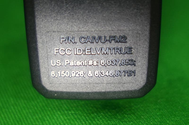
ELVMTRUE
May 29, 2021Transceiver
Equipment Class
DXX - Part 15 Low Power Communication Device Transmitter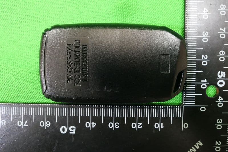
ELVMTUD
May 24, 2021Transmitter
Equipment Class
DXX - Part 15 Low Power Communication Device Transmitter