ELVATUATransmitter
Nutek Corporation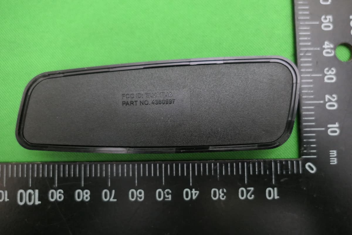
Click to zoom
Application Details
- Equipment Class
- DXX - Part 15 Low Power Communication Device Transmitter
- Date of Grant
- Nov 19, 2020
- Application Purpose
- Original Equipment
- Date of Application
- Nov 18, 2020
- Equipment Note
- Transmitter
- Frequency Range
- 2402.00000000 - 2480.00000000
- Company
- Nutek Corporation
- Country
- Taiwan
Documents & Files
Document Text
Text extracted from the exhibit documents filed with the FCC. Open a document above to read the original.
Users Manual
INSTALL GUIDE WIRELESS KEYPAD ADVENTPRODUCTS.COM 22020 Voxx Electronics Corporation. All rights reserved. Installation Installation The Pursuit wireless keypad is designed to be placed on the driver’s door “B Pillar.” The rear slanted keypad should be places on the door pillar with the keypad angled to the rear. Clean and prep the installation area with a isopropyl alcohol based solution. Allow the surface to dry completely before placing the keypad on the pillar. Remove the red plastic backing from the adhesive pad on the rear of the keypad. Place the keypad on the door pillar so that the keypad is angled (Slanted) to the rear. Press firmly for 60 seconds to ensure the adhesive properly adheres to the vehicle. Programming Locate the valet override button inside the vehicle. The vehicle’s door must be open until programming is complete. To Program the keypad: 1. Set the vehicle’s ignition to the ON position. 2. Press and release the valet override button three (3) times. The system will beep one (1) time to confirm it has entered remote programming. 3. Press and release the 7/8 and the 9/0 buttons. The system will beep one (1) time to confirm the keypad has be programmed successfully. Note: The security system can store up to four (4) remote controls in its memory banks. This can be any combination of four (4) keypad or key chain remote controls. Any remote control programmed after four (4) will automatically delete the oldest remote control in the memory bank. Programming Personal Pin Code (Optional) The keypad master unlock code cannot be changed or deleted. The keypad can learn and store a personal pin code. This code can be changed at any time. To Program a Personal Pin Code: 1. Enter the five (5) digit master code. 2. Within five (5) seconds press and hold the 1/2 button for one (1) second. The keypad LED will flash two (2) times. 3. Within five (5) seconds, enter the new Personal Pin Code. The keypad LED will flash two (2) times to confirm the Pin Code has been stored. 32020 Voxx Electronics Corporation. All rights reserved. Using Your Remote Control Locking the Vehicle To lock the vehicle, exit the vehicle, close all doors, then press and release the 7/8 & 9/0 buttons at the same time. The parking lights will flash one (1) time, indicating the system is armed, has locked the doors (if equipped and connected) and activated the starter disable feature. The LED status indicator will blink steadily, once per second. NOTE: The system is equipped with a feature called Silent Choice. If enabled, the system requires a second press of the 7/8 & 9/0 buttons to activate an audible arming response from the vehicle. Two Stage Door Unlock (Optional) If this feature is enabled entering the five (5) digit unlock code will unlock the driver’s door only. To unlock all doors, enter the five (5) digit unlock code then press and release the 3/4 button within five (5) seconds Unlocking the Vehicle To unlock the vehicle enter the five (5) digit unlock code. The parking lights will flash two (2) times, indicating the system is disarmed and has unlocked the doors (if equipped and connected). Activating the Trunk Release Feature (Optional) If this feature is enabled on your system, enter the five (5) digit unlock code then press and release the 7/8 button within five (5) seconds. Using the Personal Protection Alarm (Panic) To activate the Panic alarm, enter the five (5) digit unlock code then press and hold the 5/6 button for five (5) seconds. To stop the alarm, enter the five (5) digit unlock code or press the lock functions (Press and release the 7/8 & 9/0 buttons). The system will automatically stop after thirty (30) seconds. Deleting Personal Pin Code To deleted the Personal Pin Code: 1. Enter the five (5) digit master code. 2. Within five (5) seconds press and hold the 1/2 button for five (5) second. The keypad LED will flash four (4) times to confirm the pin code has been deleted. 42020 Voxx Electronics Corporation. All rights reserved. Voxx Electronics Corporation. Customer Service 1-800-225-6074 www.AdventProducts.com PATENTED: www.voxxintl.com/company/patents FCC COMPLIANCE This device complies with Part 15 of the FCC rules. Operation is subject to the following two conditions: 1. This device may not cause harmful interference, and 2. This device must accept any interference received, including any interference that may cause undesired operation. Warning! Changes or modifications not expressly approved by the party responsible for compliance could void the user’s authority to operate the equipment.
External Photos
Report No.: 20A073005R-FR2 FCC ID:ELVATUA Page 32 of 37 Interocean EMC Technology Corp. Test Report 7 Photographs of EUT Front View of EUT Rear View of EUT Report No.: 20A073005R-FR2 FCC ID:ELVATUA Page 33 of 37 Interocean EMC Technology Corp. Test Report FCC ID Location
Internal Photos
Report No.:20A073005R-FR1 FCC ID:ELVATUA Page 23 of 26 Interocean EMC Technology Corp. Test Report Inner View of EUT-1 Inner View of EUT-2 Report No.:20A073005R-FR1 FCC ID:ELVATUA Page 24 of 26 Interocean EMC Technology Corp. Test Report Inner View of EUT-3 Inner View of EUT-4 Report No.:20A073005R-FR1 FCC ID:ELVATUA Page 25 of 26 Interocean EMC Technology Corp. Test Report Component View of Main Board Solder View of Main Board Report No.:20A073005R-FR1 FCC ID:ELVATUA Page 26 of 26 Interocean EMC Technology Corp. Test Report View of Module View of Antenna Location Report No.: 20A073005R-FR2 FCC ID:ELVATUA Page 34 of 37 Interocean EMC Technology Corp. Test Report Inner View of EUT-1 Inner View of EUT-2 Report No.: 20A073005R-FR2 FCC ID:ELVATUA Page 35 of 37 Interocean EMC Technology Corp. Test Report Inner View of EUT-3 Inner View of EUT-4 Report No.: 20A073005R-FR2 FCC ID:ELVATUA Page 36 of 37 Interocean EMC Technology Corp. Test Report Component View of Main Board Solder View of Main Board Report No.: 20A073005R-FR2 FCC ID:ELVATUA Page 37 of 37 Interocean EMC Technology Corp. Test Report View of Module View of Antenna Location
Test Report
Report No.: 20A073005R-FR2 FCC ID:ELVATUA Page 1 of 37 Interocean EMC Technology Corp. Test Report 47 CFR Part 15 Subpart C Section 15.249 Test Report Product: Transmitter Trade Name: Pursuit Model Number: 4360997 FCC ID: ELVATUA Prepared for Nutek Corporation No.167, Lane 235, Bauchiau Rd., Xindian District, New Taipei City 23145, Taiwan TEL.: +886 2 2918 9478 FAX.: +886 2 2917 9069 Prepared by Interocean EMC Technology Corp. Interocean EMC Technology Tin-Fu Laboratory No. 5-2, Lin 1, Tin-Fu, Lin-Kou Dist., New Taipei City, Taiwan 244, R.O.C. TEL.: +886 2 2600 6861 FAX.: +886 2 2600 6859 Remark: The test report consists of 37 pages in total. It shall not be reproduced except in full, without the written approval of IETC. This document may be altered or revised by IETC only, and shall be noted in the revision section of the document. The test result in this report is only subjected to the test sample. Report No.: 20A073005R-FR2 FCC ID:ELVATUA Page 2 of 37 Interocean EMC Technology Corp. Test Report Table of Contents 1 General Information 4 1.1 Description of Equipment Under Test 4 1.2 Table for Carrier Frequencies 5 1.3 Test Facility 6 1.4 Test Equipment 7 1.5 Measurement Uncertainty 7 1.6 Summary of Measurement 8 2 Test Specifications 9 2.1 Test Standard 9 2.2 Operation Mode 9 2.3 Test Step of EUT 9 3 20dB Bandwidth test 10 3.1 Limit 10 3.2 Test Procedure 10 3.3 Test Result 10 4 RF Radiated spurious emission test 12 4.1 Limit 12 4.2 Configuration of Measurement 12 4.3 Test Procedure 13 4.4 The description of operation mode 13 4.5 Test Result 13 5 Emission on the Band Edge test 22 5.1 Limit 22 5.2 Configuration of Measurement 22 5.3 Test Procedure 22 5.4 Test Result 22 6 Photographs of Test 31 6.1 Radiated Emission Measurement (Below 1 GHz) 31 6.2 Radiated Emission Measurement (Above 1 GHz) 31 7 Photographs of EUT 32 Report No.: 20A073005R-FR2 FCC ID:ELVATUA Page 3 of 37 Interocean EMC Technology Corp. Test Report Statement of Compliance Applicant: Nutek Corporation Manufacturer: Nutek Corporation Product: Transmitter Model No.: 4360997 Tested Power Voltage: DC 3V Date of Final Test: Nov. 17, 2020 Revision of Report: Rev. 04 Configuration of Measurements and Standards Used: FCC Rules and Regulations Part 15 Subpart C I HEREBY CERTIFY THAT: The data shown in this report were made in accordance with the procedures given in ANSI C63.10, and the energy emitted by the device was founded to be within the limits applicable. I assume full responsibility for accuracy and completeness of these data. Note: 1. The result of the testing report relate only to the item tested. 2. This report shall not be partial reproduced without written approval by Interocean EMC Technology Corporation. 3. Judgment of conformity is based on test result, regardless of measurement uncertainty. Report Issued: 2020/11/18 Project Engineer: Approved: Ivan Wang K.C. Chen Report No.: 20A073005R-FR2 FCC ID:ELVATUA Page 4 of 37 Interocean EMC Technology Corp. Test Report 1 General Information 1.1 Description of Equipment Under Test Product : Transmitter Model Number : 4360997 Applicant : Nutek Corporation No.167, Lane 235, Bauchiau Rd., Xindian District, New Taipei City 23145, Taiwan Manufacturer : Nutek Corporation No.167, Lane 235, Bauchiau Rd., Xindian District, New Taipei City 23145, Taiwan Operating Frequency : 2402 MHz - 2480 MHz Output Power : 84.88 dBμV/m Channel Number : 40 Type of Modulation : ASK Antenna Description : PCB Antenna. maximum Peak gain: 0dBi. Measurement Software : e3; Ver: 8.120803a7-2 Date of Test : Oct. 06 ~ Nov. 17, 2020 Additional Description : 1) The test model is “4360997” and included in this report. 2) For more detail specification about EUT, please refer to the user’s manual. Report No.: 20A073005R-FR2 FCC ID:ELVATUA Page 5 of 37 Interocean EMC Technology Corp. Test Report 1.2 Table for Carrier Frequencies Channel Frequency (MHz) Channel Frequency (MHz) Channel Frequency (MHz) Channel Frequency (MHz) 1 2402 11 2422 21 2442 31 2462 2 2404 12 2424 22 2444 32 2464 3 2406 13 2426 23 2446 33 2466 4 2408 14 2428 24 2448 34 2468 5 2410 15 2430 25 2450 35 2470 6 2412 16 2432 26 2452 36 2472 7 2414 17 2434 27 2454 37 2474 8 2416 18 2436 28 2456 38 2476 9 2418 19 2438 29 2458 39 2478 10 2420 20 2440 30 2460 40 2480 Report No.: 20A073005R-FR2 FCC ID:ELVATUA Page 6 of 37 Interocean EMC Technology Corp. Test Report 1.3 Test Facility Site Description : Chamber 3 Name of Firm : Interocean EMC Technology Corp. Company web : http://www.ietc.com.tw Location : No. 5-2, Lin 1, Tin-Fu, Lin-Kou Dist., New Taipei City, Taiwan 244, R.O.C. Site Filing : Federal Communication Commissions – USA Designation No.: TW1020 (Test Firm Registration #: 651092) Designation No.: TW1113 (Test Firm Registration #: 959554) Innovation, Science and Economic Development Canada (ISED) CAB identifier: TW1113 (Ref. No 14962756) Voluntary Control Council for Interference by Information Technology Equipment (VCCI) – Japan Member No.: 1349 Registration No. (Conducted Room): C-11094 Registration No. (Conducted Room): T-11562 Registration No. (OATS 1): R-11040 Registration No. (Chamber 3): G-20080 Site Accreditation : Bureau of Standards and Metrology and Inspection (BSMI) – Taiwan, R.O.C. Accreditation No.: SL2-IN-E-0026 for CNS 13438 / CISPR 22 SL2-R1-E-0026 for CNS 13439 / CISPR 13 SL2-R2-E-0026 for CNS 13439 / CISPR 13 SL2-L1-E-0026 for CNS 14115 / CISPR 15 Taiwan Accreditation Foundation (TAF) Accreditation No.: 1113 American Association for Laboratory Accreditation (A2LA) Certificate Number: 4891.01 Vehicle Safety Certification Center (VSCC) Approval No.: TW16-11 Report No.: 20A073005R-FR2 FCC ID:ELVATUA Page 7 of 37 Interocean EMC Technology Corp. Test Report 1.4 Test Equipment Instrument Manufacturer Model Serial No. Next Cal. Date EMI Test Receiver R&S ESI7 830154/002 2021/05/05 Spectrum Analyzer R&S FSP30 100002 2021/05/12 Bilog Antenna ETC MCTD 2786B BLB17S04020 2021/05/04 Horn Antenna Schwarzbeck BBHA9120 9120D-1051 2…
Text truncated - open the document above for the full version.
Test Setup Photos
Report No.: 20A073005R-FR2 FCC ID:ELVATUA Page 31 of 37 Interocean EMC Technology Corp. Test Report 6 Photographs of Test 6.1 Radiated Emission Measurement (Below 1 GHz) 6.2 Radiated Emission Measurement (Above 1 GHz)
Contact Information
Applicant
Jason Wang
Test Firm
Interocean EMC Technology Corp.Benson Tsai
Technical Specifications
| # | Rule Parts | Frequency Range | Power Output |
|---|---|---|---|
| 1 | 15C | 2.40 GHz - 2.48 GHz | - |
Other Applications from Nutek Corporation
ELVATR6A
Sep 07, 2026Alarm module
Equipment Class
DTS - Digital Transmission SystemELVATR6B
Aug 19, 2026Vehicle Security and Remote Start System
Equipment Class
DSS - Part 15 Spread Spectrum TransmitterELVATRYA
Aug 13, 2024Transceiver
Equipment Class
DTS - Digital Transmission System
ELVMTRUE
May 29, 2021Transceiver
Equipment Class
DXX - Part 15 Low Power Communication Device Transmitter
ELVMTUD
May 24, 2021Transmitter
Equipment Class
DXX - Part 15 Low Power Communication Device Transmitter