ELVMTUCTransmitter
Nutek Corporation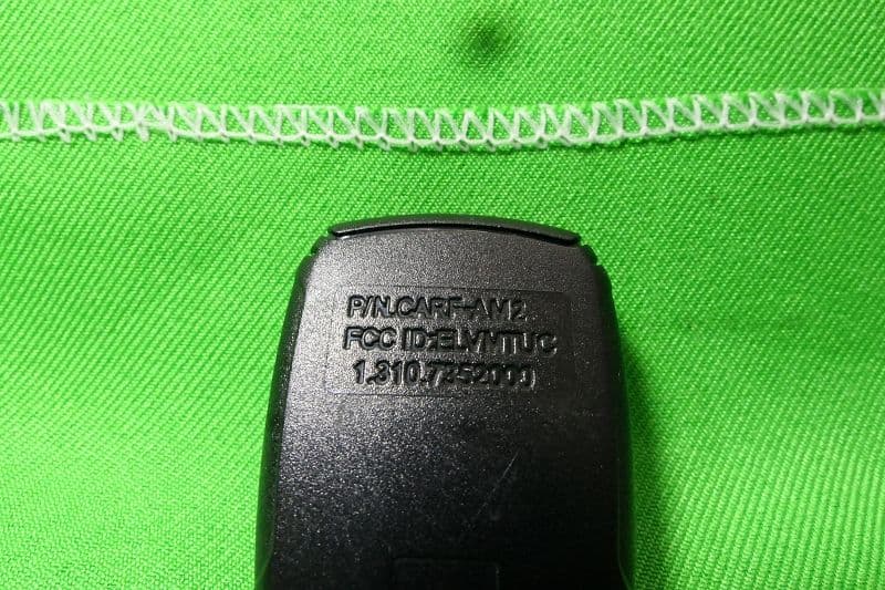
Click to zoom
Application Details
- Equipment Class
- DSC - Part 15 Security/Remote Control Transmitter
- Date of Grant
- May 12, 2021
- Application Purpose
- Original Equipment
- Date of Application
- May 11, 2021
- Equipment Note
- Transmitter
- Frequency Range
- 433.92000000 - 433.92000000
- Company
- Nutek Corporation
- Country
- Taiwan
Documents & Files
Document Text
Text extracted from the exhibit documents filed with the FCC. Open a document above to read the original.
Users Manual
1 OWNER’ S MANUAL REMOTE START with KEYLESS ENTRY SYSTEM ® 3 Congratulations Congratulations on the purchase of this CARBINE keyless entry and remote start system. Reading this owners guide prior to using the system will familiarize you with it’s many features. If issues arise or you have questions, contact your installing dealer first. Additionally, you can contact us online at www.carbine.com or call 310-735-2000. 4 Replacement Remote Controls To purchase replacement remote controls, please see your authorized dealer/installer or visit us at www.carbine.com Remote part numbers are found on the back of the remote control. 5 Contents Congratulations .............................................................................3 Replacement Remote Controls .......................................................4 Remote Control Functions ..............................................................6 Default 2-Button Remote Configuration ..........................................7 Car Finder ......................................................................................8 Start / Lock Button .........................................................................8 Timer Start Mode ...........................................................................9 Garage Mode .................................................................................9 Remote Starting the Vehicle .........................................................10 Key Takeover ...............................................................................11 Quick Stop Mode .........................................................................12 Disabling the Remote Start System ..............................................13 Pairing a Replacement Remote Control ........................................13 Safety Features ............................................................................14 Battery Replacement ...................................................................15 6 Remote Controls 2-Button Functions ButtonFeatureComment Lock the doorsPress and release Panic ModePress and hold for 3 sec or Stop the Panic Mode Press and Release Unlock the Doors with Chirps Press and Release Silent Unlock Press for 1 sec Trunk/ Hatch Release Press and hold for 3 sec + Initiate Timer Start Mode Press and release both at the same time + Car Finder Press and hold together for 1.5 seconds (2 LED flashes) Start /Stop Remote Start Sequence Press and hold for 1.5 sec (2 LED flashes) 7 Remote Controls 2-Button Functions ButtonFeatureComment Lock the doorsPress and release Panic ModePress and hold for 3 sec or Stop the Panic Mode Press and Release Unlock the Doors with Chirps Press and Release Silent Unlock Press for 1 sec Trunk/ Hatch Release Press and hold for 3 sec + Initiate Timer Start Mode Press and release both at the same time + Car Finder Press and hold together for 1.5 seconds (2 LED flashes) Start /Stop Remote Start Sequence Press and hold for 1.5 sec (2 LED flashes) Default Configuration Button - Press and release the button to lock the doors. The parking lights will flash one time. (door lock control must be installed) Button - Press and release the button to unlock the doors. The parking lights will flash two times. (door lock control must be installed) Panic Mode - Press and hold the button for 3 LED light flashes to activate panic mode. Once activated, the panic mode will sound the horn or siren and flash the parking lights for 30 seconds. - Press and release the or button to stop the panic mode Button Trunk Release Press and hold the button for 2 LED light flashes to release the trunk/ hatch lid - The vehicle must have electronic trunk control - The trunk release control option must be installed 8 Car Finder Press the and buttons together for 1.5 seconds (2 LED flashes) to initiate the Car Finder function. The parking lights will flash slowly five times. Note: This feature can be activated whether the vehicle is locked or not. Button Press and hold this button for 1.5 sec (2 LED flashes) to initiate the remote start sequence. Once the engine is running, press and release the button again for 1.5 sec (2 LED flashes) to stop the remote start operation if needed. Note: The default setting for the remote start feature is one press. This control can be re-programmed by the installer to require up to three presses to initiate the remote start function. 9 Timer Start Mode: Press the and buttons at the same time to activate timer start mode. When timer start mode is activated, the parking lights will flash four times. After a one second delay, the engine starts. Use the button to turn the engine off without exiting the timer start mode. With timer mode active, the engine will auto start every (3) hours for a maximum of (6) start cycles. Turning ON the ignition key or pressing the bake will shut off the timer start mode. When the timer mode is shut down, the parking lights will flash (4) times. Garage Mode Garage mode is a safety feature that disables the remote start function if the vehicle is parked in a garage for a long period of time or if the vehicle is being serviced. When the garage model is active, any attempt to start the engine by remote control, timer start or Quick Stop mode will be denied. Garage Mode Operation 1. Turn the ignition key On then Off. 2. Press and release the RCC button one time. - The RCC LED will turn On. 3. The parking lights will flash - 9 Times fast to indicate Garage Mode is Active - 9 Times slow to indicate that Garage Mode is Off 4. Repeat 1 and 2 turn Garage Mode off. 10 Remote Starting the Vehicle Warning! 1) Never remote start your vehicle when the keys are in the ignition. 2) Never start the vehicle unless the transmission is in PARK or NEUTRAL. 3) Never start your vehicle while it is inside a building that has minimal ventilation. 1. Make sure the parking brake is set ON. 2. Press and release the one time (or the amount of times programmed by the installer). 3. The p…
Text truncated - open the document above for the full version.
Cover Letter(s)
DATE : 2021/05/03 FCC ID: ELVMTUC D ear Sir, I hereby have entrusted the following person to be a proxy regarding application for Type Certification. Company name: Interocean EMC Technology Tin-Fu Laboratory Ad dress: No. 5-2, Lin 1, Tin-Fu, Lin-Kou Dist., New Taipei City, Taiwan 244, R.O.C. Name: Jerry Chang For instances where our authorized agent signs the application for certification on our behalf, I acknowledge that all responsibility for complying with the terms and conditions for certification, as specified by Nemko North America, Inc, still resides with us. Signature FCC grantee contact person information. N ame/Title: Jason Wang / Senior Manager Company Name: Nutek Corporation Address: No.167, Lane 235, Bauchiau Rd., Xindian District, New Taipei City 23145, Taiwan TEL: +886 2 2918 9478 FA X: +886 2 2917 9069 Em ail: [email protected]
Cover Letter(s)
DATE : 2021/0 5/03 Equipment Autorisation Division Federal Communications Commission 7 435 Oakland Mills Road Columbia, MD 21046 F CC ID: ELVMTUC Request for Confidentiality Pursuant to Sections 0.457 and 0.459 of the commissions rules, we hereby request that the following documents be held confidential: • Schematics • Block diagram • Operation description These materials contain trade secrets and proprietary information and are not customarily released to the public. The public disclosure of this information might be harmful to the company and provide unjustified benefits to our competitors. Signature FCC grantee contact person information. Name/Title: Jason Wang / Senior Manager Company Name: Nutek Corporation Address: No.167, Lane 235, Bauchiau Rd., Xindian District, New Taipei City 23145, Taiwan TEL: +886 2 2918 9478 FAX: +886 2 2917 9069 Email: [email protected]
External Photos
Report No.:21A032502R-FR FCC ID:ELVMTUC Page 21 of 25 Interocean EMC Technology Corp. Test Report 8 Photographs of EUT 8.1 Model No.: CARF-AM2 Front View of EUT Rear View of EUT Report No.:21A032502R-FR FCC ID:ELVMTUC Page 22 of 25 Interocean EMC Technology Corp. Test Report FCC ID Location
Internal Photos
Report No.:21A032502R-FR FCC ID:ELVMTUC Page 23 of 25 Interocean EMC Technology Corp. Test Report Inner View of EUT-1 Inner View of EUT-2 Report No.:21A032502R-FR FCC ID:ELVMTUC Page 24 of 25 Interocean EMC Technology Corp. Test Report Component View of Main Board Solder View of Main Board Report No.:21A032502R-FR FCC ID:ELVMTUC Page 25 of 25 Interocean EMC Technology Corp. Test Report View of Module View of Antenna Location
Test Report
Report No.:21A032502R-FR FCC ID:ELVMTUC Page 1 of 25 Interocean EMC Technology Corp. Test Report 47 CFR Part 15 Subpart C Section 15.231 Test Report Product: Transmitter Trade Name: N/A Model Number: CARF-AM2; SLRF-AM2 FCC ID: ELVMTUC Prepared for Nutek Corporation No.167, Lane 235, Bauchiau Rd., Xindian District, New Taipei City 23145, Taiwan TEL.: +886 2 2918 9478 FAX.: +886 2 2917 9069 Prepared by Interocean EMC Technology Corp. Interocean EMC Technology Tin-Fu Laboratory No. 5-2, Lin 1, Tin-Fu, Lin-Kou Dist., New Taipei City, Taiwan 244, R.O.C. TEL.: +886 2 2600 6861 FAX.: +886 2 2600 6859 Remark: The test report consists of 25 pages in total. It shall not be reproduced except in full, without the written approval of IETC. This document may be altered or revised by IETC only, and shall be noted in the revision section of the document. The test result in this report is only subjected to the test sample. Report No.:21A032502R-FR FCC ID:ELVMTUC Page 2 of 25 Interocean EMC Technology Corp. Test Report Table of Contents 1 General Information 4 1.1 Description of Equipment Under Test 4 1.2 Test Facility 5 1.3 Test Equipment 6 1.4 Measurement Uncertainty 6 1.5 Summary of Measurement 7 2 Test Specifications 8 2.1 Test Standard 8 2.2 Operation Mode 8 2.3 Test Step of EUT 8 3 Duty Cycle 9 3.1 Limits 9 3.2 Test Procedure 9 3.3 Test Result 9 4 Transmitter Deactivation Time 12 4.1 Limits 12 4.2 Test Procedure 12 4.3 Test Result 12 5 Radiated Emission Test 13 5.1 Limits 13 5.2 Configuration of Measurement 14 5.3 Test Procedure 14 5.4 Test Result 14 6 Emission Bandwidth 19 6.1 Limits 19 6.2 Test Procedure 19 6.3 Test Result 19 7 Photographs of Test 20 7.1 Radiated Emission Measurement (Below 1 GHz) 20 7.2 Radiated Emission Measurement (Above 1 GHz) 20 8 Photographs of EUT 21 8.1 Model No.: CARF-AM2 21 Report No.:21A032502R-FR FCC ID:ELVMTUC Page 3 of 25 Interocean EMC Technology Corp. Test Report Statement of Compliance Applicant: Nutek Corporation Manufacturer: Nutek Corporation Product: Transmitter Model No.: CARF-AM2; SLRF-AM2 Tested Power Voltage: DC 3V Date of Final Test: Apr. 22, 2021 Revision of Report: Rev. 00 Configuration of Measurements and Standards Used: FCC Rules and Regulations Part 15 Subpart C I HEREBY CERTIFY THAT: The data shown in this report were made in accordance with the procedures given in ANSI C63.10, and the energy emitted by the device was founded to be within the limits applicable. I assume full responsibility for accuracy and completeness of these data. Note: 1. The result of the testing report relate only to the item tested. 2. This report shall not be partial reproduced without written approval by Interocean EMC Technology Corporation. 3. Judgment of conformity is based on test result, regardless of measurement uncertainty. Report Issued: 2021/05/07 Prepared by: Approved: Ivan Wang Jerry Chang Report No.:21A032502R-FR FCC ID:ELVMTUC Page 4 of 25 Interocean EMC Technology Corp. Test Report 1 General Information 1.1 Description of Equipment Under Test Product : Transmitter Model Number : CARF-AM2; SLRF-AM2 Applicant : Nutek Corporation No.167, Lane 235, Bauchiau Rd., Xindian District, New Taipei City 23145, Taiwan Manufacturer : Nutek Corporation No.167, Lane 235, Bauchiau Rd., Xindian District, New Taipei City 23145, Taiwan Power Supply : DC 3V Operating Frequency : 433.92 MHz Output Power : 80.66 dBμV/m Type of Modulation : ASK Antenna Description : PCB Antenna. maximum Peak gain: 0dBi. Measurement Software : e3; Ver: 8.120803a7-2 Receipt Date of EUT : Mar. 29, 2021 Date of Test : Apr. 19 ~ 22, 2021 Additional Description : 1) The test model is “CARF-AM2”, designated by the applicant and included in this report. 2) The differences of all models included in this report are provided by the applicant, and the lab disclaims any liability related to reporting, if incorrect, from such provision. The difference of all models is only for different market. 3) For more detailed specification about EUT, please refer to the user’s manual. Report No.:21A032502R-FR FCC ID:ELVMTUC Page 5 of 25 Interocean EMC Technology Corp. Test Report 1.2 Test Facility Site Description :Chamber 3 Name of Firm :Interocean EMC Technology Corp. Company web :http://www.ietc.com.tw Location :No. 5-2, Lin 1, Tin-Fu, Lin-Kou Dist., New Taipei City, Taiwan 244, R.O.C. Site Filing : Federal Communication Commissions – USA Designation No.: TW1020 (Test Firm Registration #: 651092) Designation No.: TW1113 (Test Firm Registration #: 959554) Innovation, Science and Economic Development Canada (ISED) CAB identifier: TW1113 (Ref. No 14962756) Voluntary Control Council for Interference by Information Technology Equipment (VCCI) – Japan Member No.: 1349 Registration No. (Conducted Room): C-11094 Registration No. (Conducted Room): T-11562 Registration No. (OATS 1): R-11040 Registration No. (Chamber 3): G-20080 Site Accreditation : Bureau of Standards and Metrology and Inspection (BSMI) – Taiwan, R.O.C. Accreditation No.: SL2-IN-E-0026 for CNS 13438 / CISPR 22 SL2-R1-E-0026 for CNS 13439 / CISPR 13 SL2-R2-E-0026 for CNS 13439 / CISPR 13 SL2-L1-E-0026 for CNS 14115 / CISPR 15 Taiwan Accreditation Foundation (TAF) Accreditation No.: 1113 American Association for Laboratory Accreditation (A2LA) Certificate Number: 4891.01 Vehicle Safety Certification Center (VSCC) Approval No.: TW16-11 Report No.:21A032502R-FR FCC ID:ELVMTUC Page 6 of 25 Interocean EMC Technology Corp. Test Report 1.3 Test Equipment Instrument Manufacturer Model Serial No. Next Cal. Date EMI Test Receiver R&S ESI7 830154/002 2021/05/05 Spectrum Analyzer R&S FSP30 100002 2021/05/12 Loop Antenna Electro-Metrics EM-6879 261 2021/09/16 Bilog Antenna ETC MCTD 2786B BLB17S04020 2021/05/04 Horn Antenna Schwarzbeck BBHA9120 9120D-1051 2021/08/03 Pre-Amplifier EMCI EMC001150 980130 2021/08/02 Pre-Amplifier EMCI EMC051845 980110 2021/07/02 RF Cable HARBOUR 27478LL142 CBL65 2021/07/28 RF Cable Marvelous Microwave MCBL-LL266.50 CBL70 2021/07/28 Meas…
Text truncated - open the document above for the full version.
Test Setup Photos
Report No.:21A032502R-FR FCC ID:ELVMTUC Page 20 of 25 Interocean EMC Technology Corp. Test Report 7 Photographs of Test 7.1 Radiated Emission Measurement (Below 1 GHz) 7.2 Radiated Emission Measurement (Above 1 GHz)
Contact Information
Applicant
Jason Wang
Test Firm
Interocean EMC Technology Tin-Fu LaboratoryBenson Tsai
Technical Specifications
| # | Rule Parts | Frequency Range | Power Output |
|---|---|---|---|
| 1 | 15.231 | 433.92 MHz - 433.92 MHz | - |
Other Applications from Nutek Corporation
ELVATR6A
Sep 07, 2026Alarm module
Equipment Class
DTS - Digital Transmission SystemELVATR6B
Aug 19, 2026Vehicle Security and Remote Start System
Equipment Class
DSS - Part 15 Spread Spectrum TransmitterELVATRYA
Aug 13, 2024Transceiver
Equipment Class
DTS - Digital Transmission System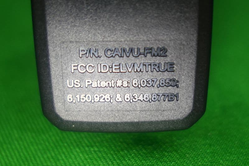
ELVMTRUE
May 29, 2021Transceiver
Equipment Class
DXX - Part 15 Low Power Communication Device Transmitter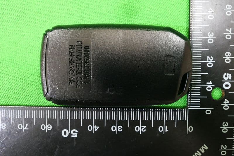
ELVMTUD
May 24, 2021Transmitter
Equipment Class
DXX - Part 15 Low Power Communication Device Transmitter