ELVNTRLFTransceiver
Nutek Corporation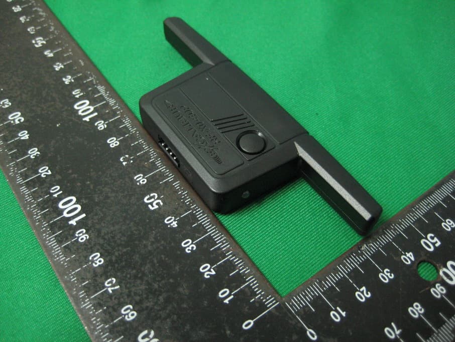
Click to zoom
Application Details
- Equipment Class
- DSR - Part 15 Remote Control/Security Device Transceiver
- Date of Grant
- Jan 06, 2013
- Application Purpose
- Original Equipment
- Date of Application
- Jan 06, 2013
- Equipment Note
- Transceiver
- Frequency Range
- 433.92000000 - 433.92000000
- Company
- Nutek Corporation
- Country
- Taiwan
Documents & Files
Document Text
Text extracted from the exhibit documents filed with the FCC. Open a document above to read the original.
Users Manual
Status Lights Valet Switch RF-50-EDP / RF-30-EDP / RF-10-EDP Range Extender / OEM Upgrade Kit Installation Guide IS_RF-X0-EDP 10/19/2012 Feature Programming: Ignition on, off, press valet 5 times # Feature Lock Button or Brake Pedal x 1 Unlock button or Brake Pedal x 2 Trunk button or Brake Pedal x 3 ”START” button or Brake Pedal x 4 1 Ignition Lock/UnlockOnLock onlyUnlock onlyOff 2 Last Door LockingOnOff 3 Automatic RelockingOnOffEnhanced 4 Unlock w/ Trunk ReleaseOnOff 5 Remote Start Activation1 press2 presses3 presses4 presses Step 1 Turn the ignition key “ON”, then “OFF” Step 2 Within 5 seconds of step 1, press the valet switch 5 times to access features ~ The built in beeper will sound and the status light will turn on. Step 3 Within 10 seconds of step 2, press the valet switch the number of times cor- responding with the desired feature’s number. ~ The built in beeper will chirp equal to the selected feature. Step 4 for RF-50-EDP & RF-30-EDP Change the feature by pressing the transmitter button that corresponds with the desired setting. Step 4 for RF-10-EDP Turn the ignition key back “ON”, some brake circuits require ignition power to operate. Change the feature by pressing the brake pedal the number of times that corresponds with the desired setting. ~ The built in beeper will chirp equal to the selected setting. Step 5 If you wish to change more features, repeat steps 3 & 4 at this time. Step 6 To exit programming, turn the ignition key “ON” then “OFF”. Or, you can wait 10 seconds for programming mode to expire. PROGRaMMInG FEatURES Programmable Features Wiring Overview Lock (-) Input - BROWn Remote Start activation (-) Input - RED/WHItE Unlock (-) Input - PURPLE/YELLOW adding Omega-Carlink Directly to RS Firmware Kit Connect the Carlink AUX outputs to these inputs and program the outputs for “1 second pulse” in the installation details during activation/configuration. Visit www.omegaweblink.com/rs for more info and current vehicle applications. RF-X0-EDP Omega Carlink Input trigger Wires { 5 AMP Constant 12 v (+) Input - RED (Not required if using a T-harness) Chassis Ground (-) Input - BL aCK (Not required if using a T-harness) Omegalink module flashed with RS firmware ~ REQUIRED ~ Window module/antenna: Mount to windshield for easy access and visibility. Programming transmitters/Controllers Step 1 Have all transmitters which are to operate the system at hand. Then, turn the ignition “on”. Step 3 2-way and 4-button controllers: Press the “lock” button on each transmitter one at a time. When the first controller is learned, all previous controllers are erased from memory. The transmitter’s other three button’s functions will automatically be assigned when the “lock” button is learned. 1-button controllers: Press the “start” button on each transmitter one at a time. When the first controller is learned, all previous controllers are erased from memory. The antenna will beep once to confirm that each was learned. NOTE: If a code is not received within a 10 second period, the learning process will automatically terminate, as indicated by a long beep. Step 2 Within 5 seconds of turning on the ignition, press the Valet Switch 5 times. The beeper in the antenna will briefly sound, confirming that for the next 10 seconds the system is ready to learn a transmitter/controller code. Installation Overview 1) Install the Omegalink RS module per the instructions provided with the chosen firmware and test for proper operation. 2) Connect to the Omegalink RS module: If using a T-harness - Connect one end of the ribbon harness to the 4 pin black connector on the T-harness. The T-harness will supply power and ground to the antenna module. the RED power and BLaCK ground wires aren’t used so make sure they are cut/capped to prevent a short circuit. If NOT using a T-harness - Connect one end of the ribbon harness to the 4 pin black connector on the RS module. Connect the RED wire to a constant +12 volt source and connect the BLaCK wire to a good chassis ground point free of paint, grease, or dirt. This will provide power to the RF module and the Omegalink RS module. 3) Connect to the RF-X0-EDP antenna module: Connect the other end of the 4 pin ribbon harness to the antenna module and test for all primary functions. 4) Mount the antenna module: Choose a mounting location high on the windshield for best operating range. Be sure that the location will not obstruct the driver’s view and is easily reached to access the valet switch. Route the ribbon harness up the A-pillar to your chosen location avoiding sharp or moving objects in the vehicle. Clean the mounting surface and attach the antenna module with the provided double-stick tape. www.caralarm.com | www.omegaweblink.com | www.wiresheet.com | www.facebook.com/omegard | 800.554.4053 This device complies with FCC Rules Part 15 Operation is subject to the following two conditions (1) This device may not cause harmful interference and (2) this device must accept any interference that may be received, including interference that may cause undesired operation. NOTE:The manufacturer is not responsible for any radio or TV interference caused by unauthorized modifications to this equipment. Such modifications could void the user’s authority to operate the equipment. FCC ID:ELVTR
Cover Letter(s)
SCS-F18: Project and Product Certification Representative Authorization Letter Page 1 of 2 Rev 3.0 775 Montague Expressway Milpitas, CA 95035 Tel: 408-526-1188 Fax: 408-526-1088 Email: [email protected] Project and Product Certification Representative Authorization Letter Revision History Reason for Amendment (current / obsolete) From To Approved Date Initial Release (obsolete) 1.0 1.0 Nov-14-2006 Revised wording (obsolete) 1.0 2.0 Sept–25-2007 Updated company template (current) 2.0 3.0 Jan-31-2012 SCS-F18: Project and Product Certification Representative Authorization Letter Page 2 of 2 Rev 3.0 Dec. 19, 2012 To: SIEMIC, INC. 775 Montague Expressway, Milpitas, CA 95035 USA Dear Sir/Madam, Re: Project and Product Certification Representative Authorization Letter We, Nutek Corporation hereby authorize SIEMIC, INC. to act as a Certification Body for certifying for the following project(s): Product: Transceiver, Model No.: RF-X0-EDP, FCC ID: ELVNTRLF We affirm that between SIEMIC and Nutek Corporation , any difference in understanding, including test plan, measurement methods, applicable standards and relevant procedures and processes have been resolved prior to commencement of testing activities. Sincerely, Client’s signature: Client’s name / title: Charles Chen / President Contact information / address: Nutek Corporation Tel: +886 2 2918 9478 Fax: +886 2 2917 9069 E-mail: [email protected]
Cover Letter(s)
SCS-F19: Confidentiality Request Letter Page 1 of 2 Rev 3.0 775 Montague Expressway Milpitas, CA 95035 Tel: 408-526-1188 Fax: 408-526-1088 Email: [email protected] Confidentiality Request Letter Revision History Reason for Amendment (current / obsolete) From To Approved Date Initial Release (obsolete) 1.0 1.0 Nov-14-2006 Adding CFR 2.459 (obsolete) 1.0 2.0 August – 11 - 2008 Updated company template & Added text box (current) 2.0 3.0 Jan-31-2012 SCS-F19: Confidentiality Request Letter Page 2 of 2 Rev 3.0 Dec. 13, 2012 To: Federal Communications Commission Authorization and Evaluation Division 7435 Oakland Mills Road Columbia, MD Subject: Permanent Confidentiality Request for FCC ID: ELVNTRLF We hereby request confidential treatment of information accompanying this application as outlined below: - Block Diagram - Schematics - Operational Description The above materials contain trade secrets and proprietary information not customarily released to the public. The public disclosure of these materials may be harmful to the applicant and provide unjustified benefits to its competitors. The applicant understands that pursuant to Section 0.457 & 0.459 of the Rules, disclosure of this application and all accompanying documentation will not be made before the date of the Grant for this application. Sincerely, Client’s signature: Client’s name / title: Charles Chen / President Contact information / address: Nutek Corporation Tel: +886 2 2918 9478 Fax: +886 2 2917 9069 E-mail: [email protected]
Cover Letter(s)
Power of Attorney Date: 2012/12/17 To whom it may concern Dear Sir / Madam, I hereby have entrusted the following person to be a proxy regarding application for FCC Certification. I am therefore responsible for the contents of the application. Project Information Product : Transceiver Model No. : RF-X0-EDP FCC ID : ELVNTRLF Company Name : Interocean EMC Technology Corp. Company Address : No., 5-2, Lin 1, Tin-Fu, Lin-Kou Dist., New Taipei City, Taiwan 244, R.O.C. Name : Jerry Liu Job Title : Manager Applicant’s Company Name : Nutek Corporation Company Address : No.167, Lane 235, Bauchiau Rd., Shindian City, Taipei County 231, Taiwan Signature : Name : Charles Chen Job Title : President E-mail : [email protected]
External Photos
Report No.:12A112102R-FR FCC ID: ELVNTRLF Page 23 of 26 Interocean EMC Technology Corp. Test Report 7 Photographs of EUT Front View of EUT Rear View of EUT Report No.:12A112102R-FR FCC ID: ELVNTRLF Page 24 of 26 Interocean EMC Technology Corp. Test Report FCC ID Location
ID Label/Location Info
MT-10010 BODY MATERIAL : HIGH HEAT ABS+UV MTF02008x2 BLACK 0.2 A ± C ± ± B NTABA0B0 R F- X 0 - E DP FCC ID : ELVNTRLF Omega Part# RF-X0-EDP433
Internal Photos
Report No.:12A112102R-FR FCC ID: ELVNTRLF Page 25 of 26 Interocean EMC Technology Corp. Test Report Inner View of EUT Antenna Location Report No.:12A112102R-FR FCC ID: ELVNTRLF Page 26 of 26 Interocean EMC Technology Corp. Test Report Component View of Main Board Solder View of Main Board
Test Report
Report No.:12A112102R-FR FCC ID: ELVNTRLF Page 1 of 26 Interocean EMC Technology Corp. Test Report CFR 47 FCC Part 15.231 TEST REPORT Product: Transceiver Trade Name: N/A Model Number: RF-X0-EDP FCC ID: ELVNTRLF Prepared for Nutek Corporation NO.167, Lane 235, Bauchiau Rd., Shindian City, Taipei County 23145, Taiwan TEL.: +886 2 2918 9478 FAX.: +886 2 2917 9069 Prepared by Interocean EMC Technology Corp. No. 5-2, Lin 1, Tin-Fu, Lin-Kou Dist., New Taipei City, Taiwan 244, R.O.C. TEL.: +886 2 2600 6861 FAX.: +886 2 2600 6859 Remark: The test report consists of 26 pages in total. It shall not be reproduced except in full, without the written approval of IETC. This document may be altered or revised by IETC only, and shall be noted in the revision section of the document. The test result in the report is only subjected to the test sample. Report No.:12A112102R-FR FCC ID: ELVNTRLF Page 2 of 26 Interocean EMC Technology Corp. Test Report Statement of Compliance Applicant: Nutek Corporation Manufacturer: Nutek Corporation Product: Transceiver Model No.: RF-X0-EDP Tested Power Supply: 12Vdc Battery Date of Final Test: Dec. 03, 2012 Configuration of Measurements and Standards Used: FCC Rules and Regulations Part 15 Subpart C 1. The result of the testing report relate only to the item tested. 2. The testing report shall not be reproduced expect in full, without the written approval of IETC. Report Issued: 2012/12/21 Project Engineer: Approved: Elli Chang Jerry Liu Report No.:12A112102R-FR FCC ID: ELVNTRLF Page 3 of 26 Interocean EMC Technology Corp. Test Report Table of Contents 1 Summary of Measurement 4 2 General Information 5 2.1 Description of Equipment Under Test 5 2.2 Details of tested peripheral equipment 6 2.3 Test Facility 7 3 Test specifications 8 3.1 Test standard 8 3.2 Operation mode 8 3.3 Test Equipment 9 4 Radiated emission test 10 4.1 Limits 10 4.2 Calculation of Average Factor 11 4.3 Configuration of Measurement 15 4.3 Configuration of Measurement 16 4.4 Test Procedure 16 4.5 Test Result 16 5 Emission bandwidth 19 5.1 Limits 19 5.2 Test Result 19 6 Photographs of Test 21 6.1 Radiated Emission Measurement 21 7 Photographs of EUT 23 Report No.:12A112102R-FR FCC ID: ELVNTRLF Page 4 of 26 Interocean EMC Technology Corp. Test Report 1 Summary of Measurement Report Clause Test Parameter Reference Document CFR47 Part15 Results 4 Timing requirement §15.231(a) Pass 4 Radiated Emission §15.231(b), 15.209 Pass 5 Emission bandwidth §15.231(c) Pass Report No.:12A112102R-FR FCC ID: ELVNTRLF Page 5 of 26 Interocean EMC Technology Corp. Test Report 2 General Information 2.1 Description of Equipment Under Test Product : Transceiver Model Number : RF-X0-EDP Applicant : Nutek Corporation NO. 167, Lane 235, Bauchiau Rd., Shindian City, Taipei County 23145, Taiwan Manufacturer : Nutek Corporation NO. 167, Lane 235, Bauchiau Rd., Shindian City, Taipei County 23145, Taiwan Power Supply : 12Vdc Battery Operating Frequency : 433.92MHz Channel Number : 1 channel Type of Modulation : ASK Antenna description : This device uses Helix antenna. The antenna is integral to the device, thereby meeting the requirement of FCC 15.203. Date of Test : Nov. 21 ~ Dec. 03, 2012 Additional Description : 1) The Model Number “RF-X0-EDP” is representative selected in the test and included in this report. 2) For more detail specification about EUT, please refer to the user’s manual. Report No.:12A112102R-FR FCC ID: ELVNTRLF Page 6 of 26 Interocean EMC Technology Corp. Test Report 2.2 Details of tested peripheral equipment N/A Report No.:12A112102R-FR FCC ID: ELVNTRLF Page 7 of 26 Interocean EMC Technology Corp. Test Report 2.3 Test Facility Site Description : OATS 2 Name of Firm : Interocean EMC Technology Corp. Company web : http://www.ietc.com.tw Site 1, 2, 3 Location : No. 5-2, Lin 1, Tin-Fu, Lin-Kou Dist., New Taipei City, Taiwan 244, R.O.C. Site Filing : z Federal Communication Commissions – USA Registration No.: 96399 (OATS 1 & 2) Registration No.: 518958 (OATS 3) Designation No.: TW1020 z Voluntary Control Council for Interference by Information Technology Equipment (VCCI) – Japan Member No.: 1349 Registration No. (Conducted Room): C-1094 Registration No. (Conducted Room): T-1562 Registration No. (OATS 1): R-1040; G-274 Registration No. (OATS 2): R-1041 z Industry Canada (IC) OUR FILE: 46405-4437 Submission: 145171 Registration No. (OATS 1): Site# 4437A-1 Registration No. (OATS 2): Site# 4437A-2 Registration No. (OATS 3): Site# 4437A-3 Site Accreditation : z Bureau of Standards and Metrology and Inspection (BSMI) – Taiwan, R.O.C. Accreditation No.: SL2-IN-E-0026 for CNS13438 / CISPR22 SL2-R1-E-0026 for CNS13439 / CISPR13 SL2-R2-E-0026 for CNS13439 / CISPR13 SL2-A1-E-0026 for CNS13783-1 / CISPR14-1 SL2-L1-E-0026 for CNS 14115 / CISPR 15 z Taiwan Accreditation Foundation (TAF) Accreditation No.: 1113 z TüV NORD Certificate No: TNTW0801R-04 Report No.:12A112102R-FR FCC ID: ELVNTRLF Page 8 of 26 Interocean EMC Technology Corp. Test Report 3 Test specifications 3.1 Test standard The EUT was performed according to FCC Part 15 Subpart C Section 15.231 procedure and setup followed by ANSI C63.4, 2003 requirements. 3.2 Operation mode N/A 3.3 Test Step of EUT 3.3.1 Setup the fixture to EUT for power supplying. 3.3.2 Turn on the power of all equipment. 3.3.3 Let the EUT continuous transmission. Executed the test. Report No.:12A112102R-FR FCC ID: ELVNTRLF Page 9 of 26 Interocean EMC Technology Corp. Test Report 3.4 Test Equipment Instrument Manufacturer Model Serial No. Next Cal. Date Spectrum Analyzer R&S FSP40 100478 2013/05/29 Preamplifier Agilent 8449B 3008A01434 2013/05/02 Preamplifier Agilent 83050A 3950A00225 2013/08/28 Horn Antenna COM-POWER AH-118 10081 2013/05/29 Horn Antenna Schwarzbeck BBHA 9120 9120D-583 2013/05/01 Horn Antenna Schwarzbeck BBHA 9170 213 2013/07/24 Cable HARBOUR 27478LL142 CBL22 2013/09/27 EMI Test Receiver Rohde & Schwarz ESCI 100836 2013/08/08 Biconical Antenna Schwarzbeck BBA 9106 VHA 9103-2419 2013/0…
Text truncated - open the document above for the full version.
Test Setup Photos
Report No.:12A112102R-FR FCC ID: ELVNTRLF Page 21 of 26 Interocean EMC Technology Corp. Test Report 6 Photographs of Test 6.1 Radiated Emission Measurement Front View of Below 1GHz Rear View of Below 1GHz Report No.:12A112102R-FR FCC ID: ELVNTRLF Page 22 of 26 Interocean EMC Technology Corp. Test Report Front View of Above 1GHz Rear View of Above 1GHz
Contact Information
Applicant
Jason Wang
Test Firm
Interocean EMC Technology Corp.Benson Tsai
Technical Specifications
| # | Rule Parts | Frequency Range | Power Output |
|---|---|---|---|
| 1 | 15.231 | 433.92 MHz - 433.92 MHz | - |
Other Applications from Nutek Corporation
ELVATR6A
Sep 07, 2026Alarm module
Equipment Class
DTS - Digital Transmission SystemELVATR6B
Aug 19, 2026Vehicle Security and Remote Start System
Equipment Class
DSS - Part 15 Spread Spectrum TransmitterELVATRYA
Aug 13, 2024Transceiver
Equipment Class
DTS - Digital Transmission System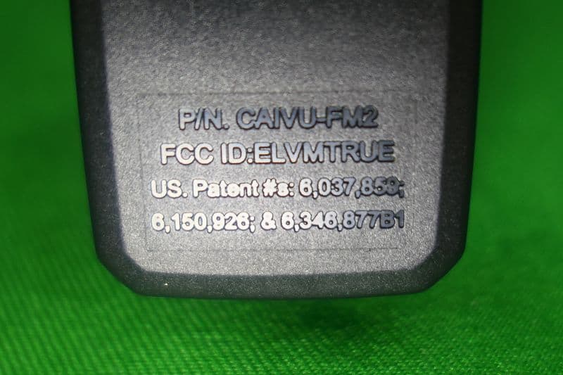
ELVMTRUE
May 29, 2021Transceiver
Equipment Class
DXX - Part 15 Low Power Communication Device Transmitter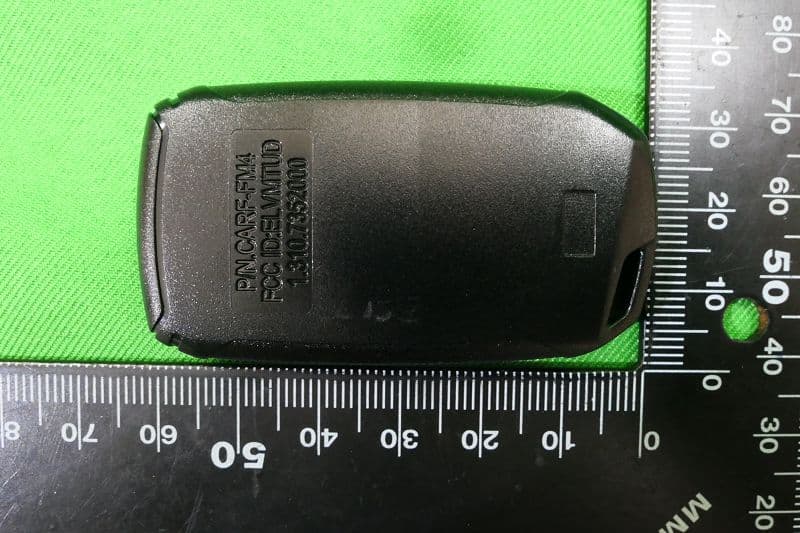
ELVMTUD
May 24, 2021Transmitter
Equipment Class
DXX - Part 15 Low Power Communication Device Transmitter