EMJHRF-QX4Wireless Bluetooth Headset
Primax Electronics Ltd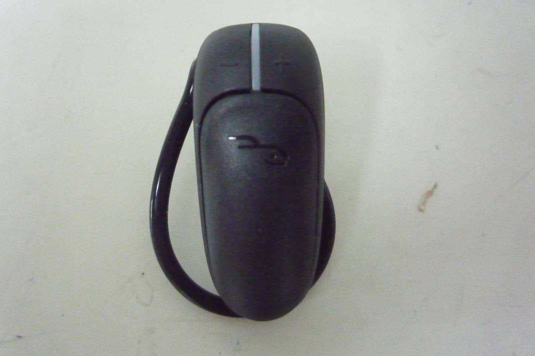
Click to zoom
Application Details
- Equipment Class
- DSS - Part 15 Spread Spectrum Transmitter
- Date of Grant
- May 08, 2011
- Application Purpose
- Original Equipment
- Date of Application
- May 04, 2011
- Equipment Note
- Wireless Bluetooth Headset
- Frequency Range
- 2402.00000000 - 2480.00000000
- Company
- Primax Electronics Ltd
- Country
- Taiwan
Documents & Files
Document Text
Text extracted from the exhibit documents filed with the FCC. Open a document above to read the original.
Users Manual
Wireless Bluetooth Headset RF-QX4/RF-QX4-T/ RF-QX4-E/RF-QX4-J User Guide 2 RF-QX4/RF-QX4-T/RF-QX4-E/RF-QX4-J Wireless Bluetooth Headset Contents Important safety instructions.......................................................3 Introduction........................................................................................4 Features ................................................................................................4 Package contents ..................................................................4 Components ...........................................................................5 Using your headset ..........................................................................6 Headset functions.................................................................6 Charging the battery ...........................................................7 Turning the headset on or off...........................................7 Pairing the headset with a compatible phone ...........7 Disconnecting the headset from the phone...............8 Reconnecting the headset to the phone .....................8 Making a call ...........................................................................8 Answering or ending a call ................................................9 Rejecting a call .......................................................................9 Redialing the last number dialed ....................................9 Muting a call............................................................................9 Using voice dialing ...............................................................9 Adjusting the headset volume...................................... 10 Switching between the headset and phone............ 10 Erasing all pairing information...................................... 10 Turning the indicator on or off ...................................... 10 Checking the battery status ........................................... 11 Resetting the headset (hardware reset)..................... 11 3 RF-QX4/RF-QX4-T/RF-QX4-E/RF-QX4-J Maintaining...................................................................................... 11 Troubleshooting............................................................................. 12 Specifications .................................................................................. 12 Legal notices.................................................................................... 12 One-year limited warranty ......................................................... 13 Important safety instructions 1Read these instructions. 2Keep these instructions. 3Heed all warnings. 4Follow all instructions. 5Do not expose the headset to water. 6Clean only with a dry cloth. 7Do not plug in the wall charger near any heat sources such as radiators, heat registers, stoves, or other chargers that produce heat. 8Do not defeat the safety purpose of the polarized or grounding-type plug. A polarized plug has two blades with one wider than the other. A grounding type plug has two blades and a third grounding prong. The wide blade or the third prong are provided for your safety. If the provided plug does not fit into your outlet, consult an electrician for replacement of the obsolete outlet. 9Protect the power cord from being walked on or pinched particularly at plugs, convenience receptacles, and the point where they exit from the charger. 10Only use attachments/accessories specified by the manufacturer. 11Unplug this charger during lightning storms or when unused for long periods of time. 12Refer all servicing to qualified service personnel. Servicing is required when the apparatus has been damaged in any way, such as power-supply cord or plug is damaged, liquid has been spilled or objects have fallen into the apparatus, the apparatus has been exposed to rain or moisture, does not operate normally, or has been dropped. 13To reduce the risk of fire or electric shock, do not expose the charger to rain, moisture, dripping, or splashing. 4 RF-QX4/RF-QX4-T/RF-QX4-E/RF-QX4-J 14An apparatus with a three-prong, grounding-type plug is a Class I apparatus, which needs to be grounded to prevent possible electric shock. Make sure that you connect this Class I device to a grounding-type, three-prong outlet. 15In order to charge your headset correctly, the wall outlet must be in correct working condition. 16Batteries should not be exposed to excessive heat. Caution: Danger of explosion if battery is incorrectly replaced. Replace only with the same or equivalent type. Wa rning: If the volume is set too high, excessive sound pressure from earphones and headphones can cause hearing loss. Introduction Congratulations on your purchase of the RF-QX4 wireless headset. This headset represents the state of the art in wireless headset design and is designed for reliable and trouble-free performance. Note: Your RF-QX4 model number may end in a letter depending on what region you are in. We use RF-QX4 in this User Guide to refer to all of the following models: •RF-QX4—United States •RF-QX4-T—Canada •RF-QX4-E—Europe •RF-QX4-J—Japan Features Package contents •RF-QX4 headset • Ear loop • Earbuds (small, medium, and large) • USB charging cable and A/C wall charger • Quick Setup Guide Note: The ear loop and medium earbud come preattached. 5 RF-QX4/RF-QX4-T/RF-QX4-E/RF-QX4-J Components #ComponentDescription 1 Power/Send/End button• Switches the headset on and off. • Answers incoming calls. • Ends active calls. • Rejects incoming calls. 2 MicrophoneTransmits your voice. 3 EarpieceTransmits the caller’s voice. 4 – (volume down button)Press to decrease the headset volume. 5 Indicator lightPower on—Lights solid green for one second and the headset beeps once. Pairing mode— Rapidly flashes green-red. The flashing continues for approximately three minutes or until the headset is connected to a compatible phone. If the headset is not connected to a phone during this time, the headset enters connectable…
Text truncated - open the document above for the full version.
External Photos
Page 1 of 3 Type Designation: RF-QX4 Report Number: 17019986 001 Fig. 1: External view Fig. 2: External view Page 2 of 3 Type Designation: RF-QX4 Report Number: 17019986 001 Fig. 3: Side view Fig. 4: Side view Page 3 of 3 Type Designation: RF-QX4 Report Number: 17019986 001 Fig. 5: Side view
ID Label/Location Info
0.2 東聚電子電訊制品有限公司 2011/04/27 此料無需承認 4 2 . 3 3 m m 18.2 mm 1:12:1 H= 3.25mm W=11.5mm H= 7mm W=5mm H= 5mm W=5mm NOTE: 1. SN FORMAT: YYMDDASSSSSS YY is a code for manufacturing year (10=2010, 11=2011......) M is a code for manufacturing mouth (Jan=A, Feb=B, Mar=C, ......Del=L) DD is a code for manufacturing day of mouth (01,02,03,......31) A is a code for factory ( Dongguan=A) SSSSSS (6 digits) is a serial number (000001~999999) Requirement of PRIMAX Green Part: 1. Comply with PRIMAX QW-5Q002“Green Product Chemical Substances Specification“. 2. Follow customer's specification as required. 3. Follow Halogen- Free requirement : Br<900 ppm, Cl<900 ppm, Br+Cl< 1500 ppm if required RF-GPS31204 LASER MARKING Quanyu Chang Sunger Lee Hongmin Hu THIS DRAWING MAY BE USED IN WHOLE OR PART T - R R 0 2 4 R E V I S E D J A N . 9 5 " B Y T H O M A S H S U MODEL: RF-GPS31204 FCC ID: EMJHRF-QX4 IC: 4251A-HRFQX4T S/N: YYMDDASSSSSS MADE IN CHINA 11.5 mm 1 6 . 4 m m MODEL: RF-GPS31204 FCC ID: EMJHRF-QX4 IC: 4251A-HRFQX4T S/N: YYMDDASSSSSS MADE IN CHINA 0.3 東聚電子電訊制品有限公司 2011/04/15 此料無需承認 4 2 . 3 3 m m 18.2 mm MODEL: RF-QX4-T IC: S/N: YYMDDASSSSSS 4251A-HRFQX4T 1:12:1 11.5 mm 1 5 . 4 m m H= 3.25mm W=11.5mm H= 7mm W=5mm H= 5mm W=5mm NOTE: 1. SN FORMAT: YYMDDASSSSSS YY is a code for manufacturing year (10=2010, 11=2011......) M is a code for manufacturing mouth (Jan=A, Feb=B, Mar=C, ......Del=L) DD is a code for manufacturing day of mouth (01,02,03,......31) A is a code for factory ( Dongguan=A) SSSSSS (6 digits) is a serial number (000001~999999) Requirement of PRIMAX Green Part: 1. Comply with PRIMAX QW-5Q002“Green Product Chemical Substances Specification“. 2. Follow customer's specification as required. 3. Follow Halogen- Free requirement : Br<900 ppm, Cl<900 ppm, Br+Cl< 1500 ppm if required RF-QX4 LASER MARKING Quanyu Chang Sunger Lee Hongmin Hu THIS DRAWING MAY BE USED IN WHOLE OR PART T - R R 0 2 4 R E V I S E D J A N . 9 5 " B Y T H O M A S H S U MODEL: RF-QX4-T IC: S/N: YYMDDASSSSSS 4251A-HRFQX4T
Internal Photos
Page 1 of 3 Type Designation: RF-QX4 Report Number: 17019986 001 Fig. 1: Internal view - Front 1 Fig. 2: Internal view - Front 2 Page 2 of 3 Type Designation: RF-QX4 Report Number: 17019986 001 Fig. 3: Internal view - Front 3 (with shielding removed) Fig. 4: Internal view - Rear 1 Page 3 of 3 Type Designation: RF-QX4 Report Number: 17019986 001 Fig. 5: Internal view - Rear 2
Test Report
Produkte Products Prüfbericht - Nr.: Test Report No. 17019986 001 Seite 2 von 50 Page 2 of 50 TEST SUMMARY 5.1.1 ANTENNA REQUIREMENT RESULT: Passed 5.1.2 PEAK OUTPUT POWER RESULT: Passed 5.1.3 20DB BANDWIDTH RESULT: Passed 5.1.4 99% BANDWIDTH RESULT: Passed 5.1.5 CONDUCTED SPURIOUS EMISSIONS MEASURED IN 100KHZ BANDWIDTH RESULT: Passed 5.1.6 SPURIOUS EMISSION RESULT: Passed 5.1.7 FREQUENCY SEPARATION RESULT: Passed 5.1.8 NUMBER OF HOPPING FREQUENCY RESULT: Passed 5.1.9 TIME OF OCCUPANCY RESULT: Passed 5.1.10 CONDUCTED EMISSIONS RESULT: Passed 5.1.11 RADIATED EMISSIONS RESULT: Passed 6.1.1 ELECTROMAGNETIC FIELDS RESULT: Passed Produkte Products Prüfbericht - Nr.: Test Report No. 17019986 001 Seite 3 von 50 Page 3 of 50 Contents 1. GENERAL REMARKS......................................................................................................... 4 1.1 COMPLEMENTARY MATERIALS.......................................................................................... 4 2. TEST SITES...................................................................................................................... 4 2.1 TEST FACILITIES............................................................................................................... 4 2.2 LIST OF TEST AND MEASUREMENT INSTRUMENTS............................................................... 5 2.3 TRACEABILITY.................................................................................................................. 6 2.4 CALIBRATION................................................................................................................... 6 2.5 MEASUREMENT UNCERTAINTY........................................................................................... 6 2.6 LOCATION OF ORIGINAL DATA........................................................................................... 6 2.7 STATUS OF FACILITY USED FOR TESTING........................................................................... 6 3. GENERAL PRODUCT INFORMATION.................................................................................... 7 3.1 PRODUCT FUNCTION AND INTENDED USE........................................................................... 7 3.2 RATINGS AND SYSTEM DETAILS........................................................................................ 7 3.3 INDEPENDENT OPERATION MODES.................................................................................... 8 3.4 NOISE GENERATING AND NOISE SUPPRESSING PARTS....................................................... 9 3.5 SUBMITTED DOCUMENTS.................................................................................................. 9 4. TEST SET-UP AND OPERATION MODES............................................................................ 10 4.1 PRINCIPLE OF CONFIGURATION SELECTION...................................................................... 10 4.2 TEST OPERATION AND TEST SOFTWARE.......................................................................... 10 4.3 SPECIAL ACCESSORIES AND AUXILIARY EQUIPMENT........................................................ 10 4.4 COUNTERMEASURES TO ACHIEVE EMC COMPLIANCE....................................................... 11 4.5 TEST SETUP DIAGRAM.................................................................................................... 11 5. TEST RESULTS............................................................................................................... 13 5.1 TRANSMITTER REQUIREMENT & TEST SUITES.................................................................. 13 5.1.1 Antenna Requirement ................................................................................................................13 5.1.2 Peak Output Power ....................................................................................................................14 5.1.3 20dB Bandwidth .........................................................................................................................18 5.1.4 99% Bandwidth ..........................................................................................................................22 5.1.5 Conducted spurious emissions measured in 100kHz Bandwidth ..............................................26 5.1.6 Spurious Emission .....................................................................................................................32 5.1.7 Frequency Separation................................................................................................................33 5.1.8 Number of hopping frequency....................................................................................................36 5.1.9 Time of Occupancy ....................................................................................................................38 5.1.10 Conducted emissions ............................................................................................................44 5.1.11 Radiated emissions ...............................................................................................................45 6. SAFETY HUMAN EXPOSURE............................................................................................. 46 6.1 RADIO FREQUENCY EXPOSURE COMPLIANCE................................................................... 46 6.1.1 Electromagnetic Fields ...............................................................................................................46 7. PHOTOGRAPHS OF THE TEST SET-UP.............................................................................. 47 Produkte Products Prüfbericht - Nr.: Test Report No. 17019986 001 Seite 4 von 50 Page 4 of 50 8. LIST OF TABLES............................................................................................................. 50 9. LIST OF PHOTOGRAPHS.................................................................................................. 50 1. General Remarks 1.1 Comp…
Text truncated - open the document above for the full version.
Test Setup Photos
Produkte Products Prüfbericht - Nr.: Test Report No. 17019986 001 Seite 41 von 44 Page 41 of 44 7. Photographs of the Test Set-Up Photograph 1: Set-up for Radiated Emissions Photograph 2: Set-up for Coducted Emissions Produkte Products Prüfbericht - Nr.: Test Report No. 17019986 001 Seite 42 von 44 Page 42 of 44 Photograph 3: Set-up for Spurious Emissions (9kHz-30MHz) Photograph 4: Set-up for Spurious Emissions (30MHz-1GHz) Produkte Products Prüfbericht - Nr.: Test Report No. 17019986 001 Seite 43 von 44 Page 43 of 44 Photograph 5: Set-up for Spurious Emissions (1GHz-26GHz)
Contact Information
Applicant
Nelson Chou(Manager)
Test Firm
BTL Inc.Daisy Dai
Technical Specifications
| # | Rule Parts | Frequency Range | Power Output |
|---|---|---|---|
| 1 | 15C | 2.40 GHz - 2.48 GHz | 2.22 mW |
Other Applications from Primax Electronics Ltd
EMJ-BHS2705
Aug 28, 2026Wireless Headset
Equipment Class
DTS - Digital Transmission SystemEMJMMOBTN5O
Aug 22, 2024wegear MW1 Creator Mouse
Equipment Class
DTS - Digital Transmission SystemEMJDDGRFN5
Aug 22, 2024wegear MW1 2.4G Dongle
Equipment Class
DXX - Part 15 Low Power Communication Device Transmitter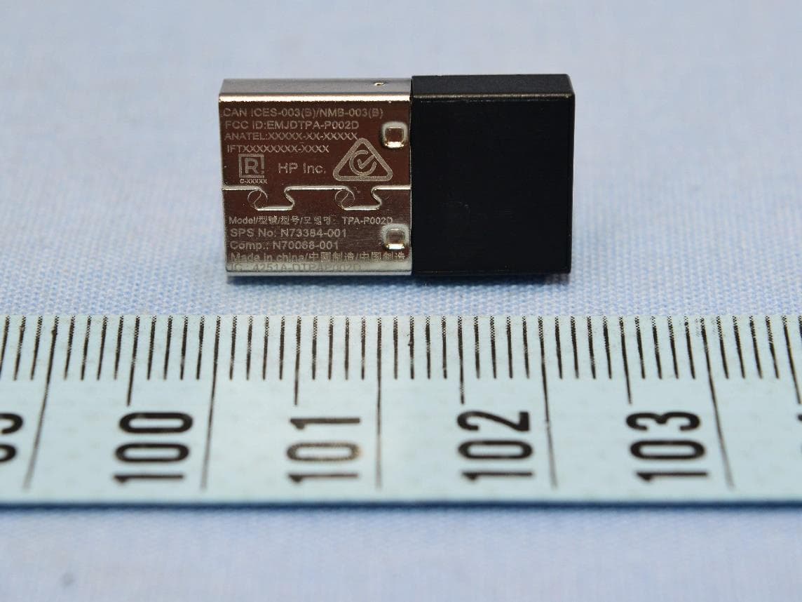
EMJDTPA-P002D
Jan 14, 2024Dongle
Equipment Class
DXX - Part 15 Low Power Communication Device Transmitter
EMJOH1
Oct 29, 2023Level Bridge
Equipment Class
DTS - Digital Transmission System