EMJMMOBTC9LThinkPad Bluetooth Laser Mouse
Primax Electronics Ltd
Click to zoom
Application Details
- Equipment Class
- DSS - Part 15 Spread Spectrum Transmitter
- Date of Grant
- Nov 01, 2007
- Application Purpose
- Original Equipment
- Date of Application
- Nov 01, 2007
- Equipment Note
- ThinkPad Bluetooth Laser Mouse
- Frequency Range
- 2402.00000000 - 2480.00000000
- Company
- Primax Electronics Ltd
- Country
- Taiwan
Documents & Files
Document Text
Text extracted from the exhibit documents filed with the FCC. Open a document above to read the original.
Users Manual
ThinkPad Bluetooth Laser Mouse User Manual About this manual Thank you for your purchase of this Bluetooth mouse set. This topics covered in this manual are listed as following. (This mouse will be sold without dongle.) ◆Introduction ◆Installing and the Batteries ◆Installing and Uninstalling the WIDCOMM Bluetooth Stack ◆Setting up the Laser Mouse ◆Using the Laser Mouse ◆Using the WIDCOMM Bluetooth Stack ◆ Troubleshooting 1. Introduction Features Laser Mouse Features • With scroll wheel and two buttons、tilt wheel • Power saving mode • LED indicator a. Amber:Low battery b. Flashing green: mouse is pairing USB Bluetooth Dongle Features • Bluetooth specification v1.2 and v2.0 compliant • Supports mouse • Supports additional Bluetooth devices System Requirements • Bluetooth / USB mouse supported computer • Microsoft Windows 98/ME/2000/XP or later 2. Installing the Batteries The mouse needs two AA size batteries. Follow the steps below to install the batteries. 1. Press the button and the battery cover pops out. 2. Install two "AA" batteries while observing the polarity (+ and -) indicated inside the mouse. 3. Replace the battery cover 3 Installing and Uninstalling the WIDCOMM Bluetooth Stack 3.1 Installing the WIDCOMM Bluetooth Stack Before installing the WIDCOMM Bluetooth stack, plug the USB Bluetooth dongle into a USB port of your computer. 1. Insert the provided Installation CD in the CD ROM drive. 2. The installation stack loads automatically. If not, click the Setup.exe in the bin folder of the CD ROM. 3. The welcome screen introduces you to the installation process. Click Next to continue. 4. Read the agreement and select “I accept he terms in the license agreement”. Click Next to continue. 5. The program will be installed in the folder as shown. Click Change to install in a different location. Click Next to continue. 6. Click Install to start the installation. The installation may need some time to complete. 7. The following screen appears to indicate the installation is complete. 8. Remove the dongle and plug it back in, the mouse will pair automatically. Click Finish to exit the installation. The following prompt requires you to restart the computer so that the Bluetooth stack takes effect. Click Yes to restart your computer now or No to restart later. 3.2 Uninstalling the WIDCOMM Bluetooth Stack Follow the steps below to uninstall the WIDCOMM Bluetooth stack from your computer. 1. Remove the USB Bluetooth dongle. 2. Click Start > Settings > Control Panel > Add/Remove Programs. 3. Select WIDCOMM Bluetooth Software from the program list and click Remove. 4. The system starts to remove the program, it may take some time to uninstall. 5. When the program has been removed, a prompt requires you to restart the computer. Click Yes to restart your computer now or No to restart later. 4. Setting up the Laser Mouse 4.1 Quick Pairing in Windows The Bluetooth mouse has been set to a pre-pairing mode as the factory default. For quick pairing, enable the pre-pairing mode following the steps below. 1. Plug the USB Bluetooth dongle into a USB port of your computer. 2. For the mouse, press the pairing button at its bottom. Pairing button 3. Press the button on the bottom of the USB Bluetooth dongle until the LED begins to flash once every second. This indicates the. Bluetooth dongle has started to search for device to be paired.( This mouse will be sold without dongle.) 4. Move your mouse to ensure they are connected. Enabling the function of USB mouse in BIOS If the mouse failed to work (refer to “7 Troubleshooting” on page 14 for more probable conditions), check that the USB function of the mouse has been enabled in the BIOS setup. Some old PC systems do not support the USB keyboard/mouse in BIOS/DOS environment. 4.2 Pairing on WIDCOMM Bluetooth Stack Before using the Bluetooth stack for mouse pairing, install the stack as instructed in “3 Installing and Uninstalling the WIDCOMM Bluetooth Stack” . Then follow the steps below. 1. Press the USB Bluetooth dongle button until the following Human Interface Device (HID) screen appears. 2. When the mouse is connected, the following confirmation message appears. Click to confirm that the correct mouse is connected. 5 Using the Laser Mouse After plugging in the USB Bluetooth dongle and setting the mouse in the Bluetooth connection environment as described in “4.Setting up the Laser Mouse” , you can begin using the mouse immediately. 5.1 Power Status of the Laser Mouse The Bluetooth mouse has a battery status LED. When the battery runs out, the LED turns amber. You should change the batteries immediately .(The top LED indicate is the same with bottom LED) To view more detailed information on the mouse battery status, go to the Control panel > Mouse > Bluetooth. LED 6. Using the WIDCOMM Bluetooth Stack 6.1 Using the Stack for the First Time To start using the Bluetooth Stack, double click the Bluetooth icon in the system tray. 1. The Initial Bluetooth Configuration Wizard will launch. Follow the instructions on screen to complete the configuration. 2. When the Bluetooth Configuration is complete, the following HID screen appears and starts to search for Bluetooth devices. 3. Click on the HID device you want to connect with. Then follow the instructions on-screen to enable the selected device. About the Bluetooth icon The Bluetooth icon acts as an indicator for dongle status. 1. A red icon indicates there is no dongle inserted. 2. A white icon indicates the dongle is plugged in. 3. A green icon indicates the dongle has detected the HID devices. 6.2 Connecting to the other HID Devices Besides the mouse, the Bluetooth Stack also allows you to connect to other Bluetooth devices. 1. Make sure the USB Bluetooth dongle has been plugged onto your computer. 2. Set the Bluetooth devices, such as printers, modems, and PDAs, you want to connect to the Bluetooth stack. 3. Press the USB Bluetooth dongle button until the following HID screen appears. 4. Select the type of …
Text truncated - open the document above for the full version.
Cover Letter(s)
Power of Attorney Date: October 25, 2007 To whom it may concern: We, the undersigned PRIMAX ELECTRONICS LTD. hereby authorize Advance Data Technology Corporation (ADT) of Taiwan to act on our behalf in all matters relating to all processes required in the FCC Part 15C approval and any communication needed with the national authority. Any and all acts carried out by ADT on our behalf shall have the same effects as acts of our own. If you have any questions regarding the authorization, please don’t hesitate to contact us. Thank you! Sincerely yours, ------------------------------------------------------------------- C.T. Huang Compliance Dept. / Director Phone: 886-2-2798-9008 ext.1710 Fax: 886-2-8797-1565 Email: [email protected]
Cover Letter(s)
Date: October 25, 2007 Federal Communications Commission Authorization and Evaluation Division Confidentiality Request FCC ID: EMJMMOBTC9L Pursuant to Sections 0.457 and 0.459 of the Commission’s Rules, the Applicant hereby requests confidential treatment of information accompanying this Application as outlined below: Schematics Block Diagram The above materials contain trade secrets and proprietary information not customarily released to the public. The public disclosure of these matters might be harmful to the Applicant and provide unjustified benefits to its competitors. The Applicant understands that pursuant to Rule 0.457, disclosure of this Application and all accompanying documentation will not be made before the date of the Grant for this application. Sincerely yours, ------------------------------------------------------------------- C.T. Huang Compliance Dept. / Director Phone: 886-2-2798-9008 ext.1710 Fax: 886-2-8797-1565 Email: [email protected]
External Photos
Page 1 CONSTRUCTION PHOTOS OF EUT
ID Label/Location Info
FCC ID: EMJMMOBTC9L FCC LABEL LOCATION The label will be permanently affixed at a conspicuous location on the device. Label
Internal Photos
Page 2 Page 3 Page 4 Page 5 Page 6
Operational Description
FCC ID: EMJMMOBTC9L Report No.: RF961004A02 Operational Description The device is a Frequency Hopping device with 79 hopping frequencies. The antenna type is Printed Antenna and there is no antenna connector used. The EUT is a unit that contains a Bluetooth radio module. Bluetooth is a short-range wireless technology operating in the 2.4GHz band. It enables devices to have the ability to form networks and exchange information. The other instruction, please have a look at the user’s manual.
RF Exposure Info
Report No: SA961004A02 1 RF EXPOSURE REPORT REPORT NO.: SA961004A02 MODEL NO.: MOBTC9L, 41U5008, 41U5009, 41U4973 ACCORDING: FCC Guidelines for Human Exposure IEEE C95.1 APPLICANT : PRIMAX ELECTRONICS LTD. ADDRESS : No. 669, Ruey Kuang Road, Neihu, Taipei, Taiwan, R.O.C. ISSUED BY : Advance Data Technology Corporation LAB ADDRESS : No. 47, 14 th Ling, Chia Pau Tsuen, Linko Hsiang 244, Taipei Hsien, Taiwan, R.O.C. Report No: SA961004A02 2 Conclusion No Evaluation Required if power is below this threshold: F(GHz) mW Low 2.402 High 2.480 24.58 Maximum measured transmitter power: Pout (dBm) Pout (mW) Conducted Power 1.21 1.321 EIRP Power -2.45 0.569 *Note: The antenna is Printed antenna with -3.66dBi gain Threshold for no SAR evaluation is 24.58mW Transmitter power is 1.321mW Conclusion: No SAR evaluation required since Transmitter Pout is below FCC threshold
Test Report
Report No.: RF961004A02 1 Report Format Version 2.0.6 FCC TEST REPORT REPORT NO.: RF961004A02 MODEL NO.: MOBTC9L, 41U5008, 41U5009, 41U4973 RECEIVED: Oct. 4, 2007 TESTED: Oct. 8 ~ 15, 2007 ISSUED: Oct. 19, 2007 APPLICANT: PRIMAX ELECTRONICS LTD. ADDRESS: No. 669, Ruey Kuang Road, Neihu, Taipei, Taiwan, R.O.C. ISSUED BY: Advance Data Technology Corporation LAB LOCATION: No. 47, 14th Ling, Chia Pau Tsuen, Lin Kou Hsiang 244, Taipei Hsien, Taiwan, R.O.C. This test report consists of 45 pages in total. It may be duplicated completely for legal use with the approval of the applicant. It should not be reproduced except in full, without the written approval of our laboratory. The client should not use it to claim product endorsement by TAF, A2LA or any government agencies. The test results in the report only apply to the tested sample. Report No.: RF961004A02 2 Report Format Version 2.0.6 TABLE OF CONTENTS 1. CERTIFICATION.............................................................................................4 2. SUMMARY OF TEST RESULTS.....................................................................5 2.1 MEASUREMENT UNCERTAINTY..................................................................6 3. GENERAL INFORMATION.............................................................................7 3.1 GENERAL DESCRIPTION OF EUT................................................................7 3.2 DESCRIPTION OF TEST MODES..................................................................8 3.2.1 CONFIGURATION OF SYSTEM UNDER TEST.............................................8 3.2.2 TEST MODE APPLICABILITY AND TESTED CHANNEL DETAIL..................9 3.3.3 GENERAL DESCRIPTION OF APPLIED STANDARDS...............................10 3.3.4 DESCRIPTION OF SUPPORT UNITS..........................................................10 4. TEST TYPES AND RESULTS.......................................................................11 4.1 CONDUCTED EMISSION MEASUREMENT................................................11 4.2 RADIATED EMISSION MEASUREMENT.....................................................11 4.2.1 LIMITS OF RADIATED EMISSION MEASUREMENT...................................11 4.2.2 TEST INSTRUMENTS..................................................................................12 4.2.3 TEST PROCEDURES...................................................................................13 4.2.4 DEVIATION FROM TEST STANDARD.........................................................13 4.2.5 TEST SETUP................................................................................................14 4.2.6 EUT OPERATING CONDITIONS..................................................................14 4.2.7 TEST RESULTS............................................................................................15 4.3 NUMBER OF HOPPING FREQUENCY USED.............................................19 4.3.1 LIMIT OF HOPPING FREQUENCY USED...................................................19 4.3.2 TEST INSTRUMENTS..................................................................................19 4.3.3 TEST PROCEDURES...................................................................................19 4.3.4 DEVIATION FROM TEST STANDARD.........................................................20 4.3.5 TEST SETUP................................................................................................20 4.3.6 TEST RESULTS............................................................................................20 4.4 DWELL TIME ON EACH CHANNEL.............................................................22 4.4.1 LIMIT OF DWELL TIME USED......................................................................22 4.4.2 TEST INSTRUMENTS..................................................................................22 4.4.3 TEST PROCEDURES...................................................................................22 4.4.4 DEVIATION FROM TEST STANDARD.........................................................22 4.4.5 TEST SETUP................................................................................................23 4.4.6 TEST RESULTS............................................................................................23 4.5 CHANNEL BANDWIDTH...............................................................................26 4.5.1 LIMITS OF CHANNEL BANDWIDTH............................................................26 4.5.2 TEST INSTRUMENTS..................................................................................26 4.5.3 TEST PROCEDURE.....................................................................................26 4.5.4 DEVIATION FROM TEST STANDARD.........................................................27 4.5.5 TEST SETUP................................................................................................27 4.5.6 EUT OPERATING CONDITION....................................................................27 4.5.7 TEST RESULTS............................................................................................27 4.6 HOPPING CHANNEL SEPARATION............................................................30 4.6.1 LIMIT OF HOPPING CHANNEL SEPARATION............................................30 Report No.: RF961004A02 3 Report Format Version 2.0.6 4.6.2 TEST INSTRUMENTS..................................................................................30 4.6.3 TEST PROCEDURES...................................................................................30 4.6.4 DEVIATION FROM TEST STANDARD.........................................................31 4.6.5 TEST SETUP................................................................................................31 4.6.6 TEST RESULTS............................................................................................31 4.7 MAXIMUM PEAK OUTPUT POWER............................................................34 4.7.1 LIMITS OF MAX…
Text truncated - open the document above for the full version.
Test Setup Photos
1 PHOTOGRAPHS OF THE TEST CONFIGURATION RADIATED EMISSION TEST
Contact Information
Applicant
Nelson Chou(Manager)
Technical Contact
Advance Data Technology Corporation (Lin Kou)Ken Liu
[email protected]886-2-2605-2180
No.47, 14 Ling, Chia Pau Tsuen, Lin Kou Hsiang · Linkou, Taipei · Taiwan
Non-Technical Contact
Advance Data Technology CorporationAnnie Chang
[email protected]886-2-2605-2180
Test Firm
Bureau Veritas CPS (H.K.) Ltd. Taoyuan BranchTommy Wu
Technical Specifications
| # | Rule Parts | Frequency Range | Power Output |
|---|---|---|---|
| 1 | 15C | 2.40 GHz - 2.48 GHz | 1.00 mW |
Other Applications from Primax Electronics Ltd
EMJ-BHS2705
Aug 28, 2026Wireless Headset
Equipment Class
DTS - Digital Transmission SystemEMJMMOBTN5O
Aug 22, 2024wegear MW1 Creator Mouse
Equipment Class
DTS - Digital Transmission SystemEMJDDGRFN5
Aug 22, 2024wegear MW1 2.4G Dongle
Equipment Class
DXX - Part 15 Low Power Communication Device Transmitter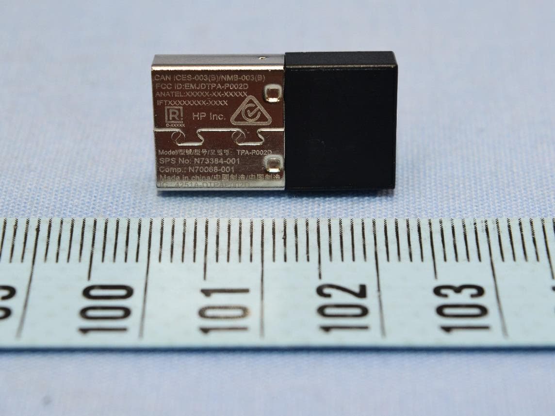
EMJDTPA-P002D
Jan 14, 2024Dongle
Equipment Class
DXX - Part 15 Low Power Communication Device Transmitter
EMJOH1
Oct 29, 2023Level Bridge
Equipment Class
DTS - Digital Transmission System