EMJMMOBTHTLMouse
Primax Electronics Ltd
Click to zoom
Application Details
- Equipment Class
- DXX - Part 15 Low Power Communication Device Transmitter
- Date of Grant
- Dec 22, 2014
- Application Purpose
- Original Equipment
- Date of Application
- Dec 22, 2014
- Equipment Note
- Mouse
- Frequency Range
- 2402.00000000 - 2479.00000000
- Company
- Primax Electronics Ltd
- Country
- Taiwan
Documents & Files
Document Text
Text extracted from the exhibit documents filed with the FCC. Open a document above to read the original.
Users Manual
- 1 - Mouse Federal Communication Commission Interference Statement This device complies with Part 15 of the FCC Rules. Operation is subject to the following two conditions: (1) This device may not cause harmful interference, and (2) this device must accept any interference received, including interference that may cause undesired operation. This equipment has been tested and found to comply with the limits for a Class B digital device, pursuant to Part 15 of the FCC Rules. These limits are designed to provide reasonable protection against harmful interference in a residential installation. This equipment generates, uses and can radiate radio frequency energy and, if not installed and used in accordance with the instructions, may cause harmful interference to radio communications. However, there is no guarantee that interference will not occur in a particular installation. If this equipment does cause harmful interference to radio or television reception, which can be determined by turning the equipment off and on, the user is encouraged to try to correct the interference by one of the following measures: - Reorient or relocate the receiving antenna. - Increase the separation between the equipment and receiver. - Connect the equipment into an outlet on a circuit different from that to which the receiver is connected. - Consult the dealer or an experienced radio/TV technician for help. FCC Caution: Any changes or modifications not expressly approved by the party responsible for compliance could void the user's authority to operate this equipment. This transmitter must not be co-located or operating in conjunction with any other antenna or transmitter. Radiation Exposure Statement: The product comply with the FCC portable RF exposure limit set forth for an uncontrolled environment and are safe for intended operation as described in this manual. The further RF exposure reduction can be achieved if the product can be kept as far as possible from the user body or set the device to lower output power if such function is available. Copyright Copyright 2014 Primax. All rights reserved. No part of this publication may be reproduced, transmitted, transcribed, stored in a retrieval system, or translated into any language or computer language, in any form or by any means, electronic, mechanical, magnetic, optical, chemical, manual, or otherwise, without the prior written permission of Primax Trademarks Primax is a registered trademark of Primax. All other trademarks used in this documentation are the sole property of their respective owners. - 2 - Setting Up Your Mouse Connecting the USB Mouse Note: To use the USB mouse, you need to have Windows Win7,Win8,Win8.1 installed on your computer. • You don’t need to turn off your computer before connect your USB mouse. • Plug the rectangular USB mouse connector into the USB port (normally in the back of the PC). • Insert the software diskette into your disk drive and follow the onscreen instructions to install the device driver. - 3 - Using the Wheel Note: This section is for wheel mouse only. Your new mouse may have a wheel that can be used in two ways: • Rotate it to use it as the wheel. • Click it to use it as the wheel button. Scrolling The wheel on your mouse can be used to scroll through most applications with a scroll bar. • To scroll with your mouse, simply rotate the wheel on your mouse forward or backward. AutoScrolling AutoScroll allows you to automatically scroll through a document without having to move the mouse or mouse wheel constantly in some Microsoft Office 2003 compatible applications (e.g. Microsoft Word 2003). • To AutoScroll while in a document, click the mouse button designated as AutoScroll. An origin mark ( ) will appear at your pointer position. To start AutoScrolling, move your pointer vertically, horizontally, or diagonally away from the origin mark. AutoScroll speed increases as the pointer is moved away from the origin mark. To stop AutoScrolling, press any mouse button or rotate the wheel. Zooming In some Microsoft Office 2003 compatible applications (e.g. Microsoft Word 2003), additional zooming functions are available. You can use the zooming function to “zoom in” for a closer look at a page or “zoom out” to see more of a page. • To zoom in, hold the Ctrl key down and rotate the mouse wheel forward. • To zoom out, hold the Ctrl key down and rotate the mouse wheel backward. - 4 - Troubleshooting Reviewing the following section may help you diagnose any problems you are having with the operation or installation of your new mouse. If the problem you are experiencing is not referred to below, or the suggested solutions do not solve the problem, please contact our Technical Support staff. • Why isn’t my pointer moving smoothly? Your mouse ball and ball cage may require cleaning. Refer to the Maintenance section for proper cleaning procedures. • Why aren’t the scrolling functions of my mouse working with my notebook? On your notebook, you may need to disable the trackball, touchpad, or J-key in the BIOS and enable the external port in order to successfully use all of your mouse’s functions. • My USB mouse was not detected by the system and won’t work! Please check through the below items: • Make sure your USB mouse was completely plugged into the USB port. • Check if the USB port in your system worked properly in the Device Manager page of System Properties. If there is a circled exclamation point through the icon it means this universal serial bus controller has some problem. Please try to remove and install it again or contact the technical support of your PC manufacturer. • Check the version of your operating system. If you are not running Windows 98, Windows 2000 or above, please update your operating system such that the USB device can be enabled. • Make sure that the USB port was enabled in the BIOS setup. • Why isn’t there a pointer on the screen? or Why isn’t the pointer responding to mouse movement? Your mouse is not be…
Text truncated - open the document above for the full version.
Cover Letter(s)
No. 669, Ruey Kuang Road Neihu Taipei, Taiwan, R.O.C. Tel: 883-2-2798-9008 Fax: 886-2-8798-1565 Date: 2014-12-02 FCC ID: EMJMMOBTHTL AUTHORIZATION LETTER To whom it may concern: We, the undersigned, hereby authorize Amanda Wu / Senior Specialist of Bureau Veritas Consumer Products Services (H.K.) Ltd., Taoyuan Branch (BV CPS Taoyuan) of Taiwan to act on our behalf in all manners relating to FCC application for equipment authorization, including signing of all documents relating to these matters. Any and all acts carried out by Amanda Wu / Senior Specialist of BV CPS Taoyuan on our behalf shall have the same effect as acts of our own. If you have any questions regarding the authorization, please don’t hesitate to contact us. Sincerely yours, ------------------------------------------------------------------- C.T. Huang Compliance Dept. / Director Phone: 886-2-2798-9008 ext.1710 Fax: 886-2-8797-1565 Email: [email protected]
Cover Letter(s)
No. 669, Ruey Kuang Road Neihu Taipei, Taiwan, R.O.C. Tel: 883-2-2798-9008 Fax: 886-2-8798-1565 Date: December 2, 2014 Federal Communications Commission Authorization and Evaluation Division Confidentiality Request FCC ID: EMJMMOBTHTL Pursuant to Sections 0.457 and 0.459 of the Commission’s Rules, the Applicant hereby requests confidential treatment of information accompanying this Application as outlined below: Schematics Block Diagram The above materials contain trade secrets and proprietary information not customarily released to the public. The public disclosure of these matters might be harmful to the Applicant and provide unjustified benefits to its competitors. The Applicant understands that pursuant to Rule 0.457, disclosure of this Application and all accompanying documentation will not be made before the date of the Grant for this application. Sincerely yours, ------------------------------------------------------------------- C.T. Huang Compliance Dept. / Director Phone: 886-2-2798-9008 ext.1710 Fax: 886-2-8797-1565 Email: [email protected]
External Photos
Page 1 CONSTRUCTION PHOTOS OF EUT
ID Label/Location Info
Label Location 304009999010 1234567 123457 A B C D E A B C D REV. DESCRIPTION ENG. APPROVAL NOTE: 1. Printing: Pantone black on white backgroud. 2. TOL: +0.3/-0.5mm 1/1 7. Requirement of PRIMAX Part: 1.Comply with PRIMAX QW-5Q002 "Green Substances Specifion." 2.Follow customei s specification as required., Product Chemical Apple.Zhao Helen.Yuan2014/11/27 1 3.Follow Halogen- Free requirement : Br<900 ppm, Cl<900 ppm, Br+Cl< 1500 ppm if required. 80#合成纸+雾P 3. The dimensions marked with "*" are important. 4. Glue T=0.025~0.03mm 5. Stickiness: 3.0kg/cm BOTTOM LABEL 2 6. Product must be halogen free Sarah.Lee Citrix * 4 4 m m *23.5mm 304009999010 8. S/N: YY WW XXXXXX Serial No.(From 000001.000002.000003......999999) Week(01.02...)此周別碼為生產日期,作大貨時請生管提供 Year(2014=14, 2015=15...) 1:1 2:1 S/N:YYWW000001 Rating:1.5V 40mA Model:MOBTHTL Citrix X1 Prototype Mouse FCC ID:EMJMMOBTHTL DA103787 Citrix Systems Internationl GmbH Società di partecipazioni finanziarie Rheinweg 9,8200 Schaffhausen, Switzerland Complies with 21 CFR 1040.10 and 1040.11 except for deviations pursuant to Laser Notice No. 50, dated June 24, 2007 CLASS 1 LASER PRODUCT S/N:YYWW000001 Rating:1.5V 40mA Model:MOBTHTL Citrix X1 Prototype Mouse FCC ID:EMJMMOBTHTL DA103787 Citrix Systems Internationl GmbH Società di partecipazioni finanziarie Rheinweg 9,8200 Schaffhausen, Switzerland Complies with 21 CFR 1040.10 and 1040.11 except for deviations pursuant to Laser Notice No. 50, dated June 24, 2007 CLASS 1 LASER PRODUCT
Internal Photos
Page 2 Page 3 Page 4
Operational Description
FCC ID: EMJMMOBTHTL Report No.: RF141201D09 Operational Description FOR 2.4GHz The transmitter of the EUT (Mouse) is powered by 1.5Vdc from battery. The type of antenna is Printed antenna. The output power of this device is very low. Under normal use condition, the transmitter and the receiver are quite close, so high EIRP power is neither necessary nor allowed because of interference. FOR BLUETOOTH LE4.0 The device is operates in the 2.4GHz frequency spectrum with throughput of 1Mbps which DTS technique will be applied. The transmitter of the EUT is powered by 1.5Vdc from battery. The antenna is Printed antenna. The other instruction, please have a look at the user’s manual.
RF Exposure Info
Report No.: SA141201D09 1 of 6 Report Format Version 5.0.1 RF EXPOSURE REPORT REPORT NO.: SA141201D09 MODEL NO.: MOBTHTL FCC ID: EMJMMOBTHTL RECEIVED: Dec. 1, 2014 TESTED: Dec. 18 ~ 19, 2014 ISSUED: Dec. 22, 2014 APPLICANT: PRIMAX ELECTRONICS LTD. ADDRESS: No. 669, Ruey Kuang Road, Neihu, Taipei, Taiwan, R.O.C. ISSUED BY: Bureau Veritas Consumer Products Services (H.K.) Ltd., Taoyuan Branch LAB LOCATION: No. 47-2, 14th Ling, Chia Pau Vil., Lin Kou Dist., New Taipei City, Taiwan ( R.O.C. ) This report is for your exclusive use. Any copying or replication of this report to or for any other person or entity, or use of our name or trademark, is permitted only with our prior written permission. This report sets forth our findings solely with respect to the test samples identified herein. The results set forth in this report are not indicative or representative of the quality or characteristics of the lot from which a test sample was taken or any similar or identical product unless specifically and expressly noted. Our report includes all of the tests requested by you and the results thereof based upon the information that you provided to us. You have 60 days from date of issuance of this report to notify us of any material error or omission caused by our negligence, provided, however, that such notice shall be in writing and shall specifically address the issue you wish to raise. A failure to raise such issue within the prescribed time shall constitute your unqualified acceptance of the completeness of this report, the tests conducted and the correctness of the report contents. Unless specific mention, the uncertainty of measurement has been explicitly taken into account to declare the compliance or non-compliance to the specification. Report No.: SA141201D09 2 of 6 Report Format Version 5.0.1 Table of Contents RELEASE CONTROL RECORD................................................................................. 3 1. CERTIFICATION .............................................................................................. 4 2. EVALUATION RESULT .................................................................................... 5 3. SAR TEST EXCLUSION THRESHOLDS ......................................................... 6 4. CONCLUSION ................................................................................................. 6 Report No.: SA141201D09 3 of 6 Report Format Version 5.0.1 RELEASE CONTROL RECORD ISSUE NO. REASON FOR CHANGE DATE ISSUED SA141201D09 Original release Dec. 22, 2014 Report No.: SA141201D09 4 of 6 Report Format Version 5.0.1 1. CERTIFICATION PRODUCT: Mouse BRAND NAME: PRIMAX MODEL NO.: MOBTHTL APPLICANT: PRIMAX ELECTRONICS LTD. TESTED: Dec. 18 ~ 19, 2014 TEST SAMPLE: ENGINEERING SAMPLE STANDARDS: FCC Part 2 (Section 2.1093) KDB 447498 D03 IEEE C95.1 The above equipment has been tested by Bureau Veritas Consumer Products Services (H.K.) Ltd., Taoyuan Branch, and found compliance with the requirement of the above standards. The test record, data evaluation & Equipment Under Test (EUT) configurations represented herein are true and accurate accounts of the measurements of the sample’s EMC characteristics under the conditions specified in this report. PREPARED BY : , DATE: Dec. 22, 2014 ( Jessica Cheng / Senior Specialist ) APPROVED BY : , DATE: Dec. 22, 2014 ( Rex Lai / Assistant Manager ) Report No.: SA141201D09 5 of 6 Report Format Version 5.0.1 2. EVALUATION RESULT Following FCC KDB 447498 D01 “General SAR test exclusion guidance” The corresponding SAR Exclusion Threshold condition, listed below: 1) The 1-g and 10-g SAR test exclusion thresholds for 100 MHz to 6 GHz at test separation distances ≤ 50 mm are determined by: [(max. power of channel, including tune-up tolerance, mW)/(min. test separation distance, mm)] ·[√f(GHz)] ≤ 3.0 for 1-g SAR and ≤ 7.5 for 10-g extremity SAR,16 where ÿ f(GHz) is the RF channel transmit frequency in GHz . ÿPower and distance are rounded to the nearest mW and mm befor e calculation. ÿThe result is rounded to one decimal place for comparison The test exclusions are applicable only when the minimum test separation distance is ≤ 50 mm and for transmission frequencies between 100 MHz and 6 GHz. When the minimum test separation distance is < 5 mm, a distance of 5 mm is applied to determine SAR test exclusion. 2) At 100 MHz to 6 GHz and for test separation distances > 50 mm, the SAR test exclusion threshold is determined according to the following: a) [Threshold at 50 mm in step 1) + (test separation distance - 50mm)·( f(MHz)/150)] mW, at 100MHz to 1500 MHz b) [Threshold at 50 mm in step 1) + (test separation distance - 50 mm)·10] mW at > 1500 MHz and ≤ 6 GHz 3) At frequencies below 100 MHz, the following may be considered for SAR test exclusion. a) The threshold at the corresponding test separation distance at 100 MHz in step 2) is multiplied by [1 + log(100/f(MHz))] for test separation distances > 50 mm and < 200 mm. b) The threshold determined by the equation in a) for 50 mm and 100 MHz is multiplied by ½ for test separation distances ≤ 50 mm. c) SAR measurement procedures are not established below 100 MHz. When SAR test exclusion cannot be applied, a KDB inquiry is required to determine SAR evaluation requirements for any test results to be acceptable. Report No.: SA141201D09 6 of 6 Report Format Version 5.0.1 3. SAR TEST EXCLUSION THRESHOLDS Maximum measured transmitter power: Frequency (GHz) Max. Power (mW) Min. test separation distance (mm) SAR test exclusion calculation value (NOTE 2) 1-g SAR test exclusion thresholds Result 2.402 ~ 2.480 0.3 5 0.093 3 Pass NOTE: 1. The antenna type is Printed antenna with -3.06dBi gain. 2. Calculate SAR test exclusion thresholds from condition “1” formulas. 4. CONCLUSION Since Source-base time average power is below SAR test exclusion power thresholds, the SAR evaluation is not required.
Test Report
Report No.: RF141201D09 1 of 33 Report Format Version 5.2.1 FCC TEST REPORT REPORT NO.: RF141201D09 MODEL NO.: MOBTHTL FCC ID: EMJMMOBTHTL RECEIVED: Dec. 1, 2014 TESTED: Dec. 18 ~ 19, 2014 ISSUED: Dec. 22, 2014 APPLICANT: PRIMAX ELECTRONICS LTD. ADDRESS: No. 669, Ruey Kuang Road, Neihu, Taipei, Taiwan, R.O.C. ISSUED BY: Bureau Veritas Consumer Products Services (H.K.) Ltd., Taoyuan Branch LAB ADDRESS: No. 47-2, 14th Ling, Chia Pau Vil., Lin Kou Dist., New Taipei City, Taiwan ( R.O.C. ) This report is for your exclusive use. Any copying or replication of this report to or for any other person or entity, or use of our name or trademark, is permitted only with our prior written permission. This report sets forth our findings solely with respect to the test samples identified herein. The results set forth in this report are not indicative or representative of the quality or characteristics of the lot from which a test sample was taken or any similar or identical product unless specifically and expressly noted. Our report includes all of the tests requested by you and the results thereof based upon the information that you provided to us. You have 60 days from date of issuance of this report to notify us of any material error or omission caused by our negligence, provided, however, that such notice shall be in writing and shall specifically address the issue you wish to raise. A failure to raise such issue within the prescribed time shall constitute your unqualified acceptance of the completeness of this report, the tests conducted and the correctness of the report contents. Unless specific mention, the uncertainty of measurement has been explicitly taken into account to declare the compliance or non-compliance to the specification. This report should not be used by the client to claim product certification, approval, or endorsement by TAF or any government agencies. Report No.: RF141201D09 2 of 33 Report Format Version 5.2.1 Table of Contents RELEASE CONTROL RECORD............................................................................. 4 1. CERTIFICATION .......................................................................................... 5 2. SUMMARY OF TEST RESULTS .................................................................. 6 2.1 MEASUREMENT UNCERTAINTY ............................................................... 6 3. GENERAL INFORMATION .......................................................................... 7 3.1 GENERAL DESCRIPTION OF EUT ............................................................. 7 3.2 DESCRIPTION OF TEST MODES ............................................................... 8 3.2.1 TEST MODE APPLICABILITY AND TESTED CHANNEL DETAIL ............... 9 3.3 DUTY CYCLE OF TEST SIGNAL............................................................... 11 3.4 DESCRIPTION OF SUPPORT UNITS ....................................................... 12 3.4.1 CONFIGURATION OF SYSTEM UNDER TEST ........................................ 12 3.5 GENERAL DESCRIPTION OF APPLIED STANDARDS ............................ 13 4. TEST TYPES AND RESULTS .................................................................... 14 4.1 RADIATED EMISSION AND BANDEDGE MEASUREMENT ..................... 14 4.1.1 LIMITS OF RADIATED EMISSION AND BANDEDGE MEASUREMENT...................................................................................... 14 4.1.2 TEST INSTRUMENTS ............................................................................... 15 4.1.3 TEST PROCEDURES ................................................................................ 16 4.1.4 DEVIATION FROM TEST STANDARD ...................................................... 16 4.1.5 TEST SETUP ............................................................................................. 17 4.1.6 EUT OPERATING CONDITIONS ............................................................... 17 4.1.7 TEST RESULTS ......................................................................................... 18 4.2 CONDUCTED EMISSION MEASUREMENT ............................................. 22 4.3 6DB BANDWIDTH MEASUREMENT ......................................................... 22 4.3.1 LIMITS OF 6DB BANDWIDTH MEASUREMENT ...................................... 22 4.3.2 TEST SETUP ............................................................................................. 22 4.3.3 TEST INSTRUMENTS ............................................................................... 22 4.3.4 TEST PROCEDURE .................................................................................. 22 4.3.5 DEVIATION FROM TEST STANDARD ...................................................... 22 4.3.6 EUT OPERATING CONDITIONS ............................................................... 22 4.3.7 TEST RESULTS ......................................................................................... 23 4.4 CONDUCTED OUTPUT POWER .............................................................. 24 4.4.1 LIMITS OF CONDUCTED OUTPUT POWER MEASUREMENT ............... 24 4.4.2 TEST SETUP ............................................................................................. 24 4.4.3 TEST INSTRUMENTS ............................................................................... 24 4.4.4 TEST PROCEDURES ................................................................................ 24 4.4.5 DEVIATION FROM TEST STANDARD ...................................................... 24 4.4.6 EUT OPERATING CONDITIONS ............................................................... 24 4.4.7 TEST RESULTS ......................................................................................... 25 4.5 POWER SPECTRAL DENSITY MEASUREMENT ..................................... 26 4.5.1 LIMITS OF POWER SPECTRAL DENSITY MEASUREMENT .................. 26 4.5.2 TEST SETUP ............................................................................................. 26 4.5.3 TEST INST…
Text truncated - open the document above for the full version.
Test Report
Report No.: RF141201D09-1 1 of 21 Report Format Version 5.0.0 FCC TEST REPORT REPORT NO.: RF141201D09-1 MODEL NO.: MOBTHTL FCC ID: EMJMMOBTHTL RECEIVED: Dec. 1, 2014 TESTED: Dec. 4, 2014 ISSUED: Dec. 22, 2014 APPLICANT: PRIMAX ELECTRONICS LTD. ADDRESS: No. 669, Ruey Kuang Road, Neihu, Taipei, Taiwan, R.O.C. ISSUED BY: Bureau Veritas Consumer Products Services (H.K.) Ltd., Taoyuan Branch LAB LOCATION: No. 47-2, 14th Ling, Chia Pau Vil., Lin Kou Dist., New Taipei City, Taiwan ( R.O.C. ) This report is for your exclusive use. Any copying or replication of this report to or for any other person or entity, or use of our name or trademark, is permitted only with our prior written permission. This report sets forth our findings solely with respect to the test samples identified herein. The results set forth in this report are not indicative or representative of the quality or characteristics of the lot from which a test sample was taken or any similar or identical product unless specifically and expressly noted. Our report includes all of the tests requested by you and the results thereof based upon the information that you provided to us. You have 60 days from date of issuance of this report to notify us of any material error or omission caused by our negligence, provided, however, that such notice shall be in writing and shall specifically address the issue you wish to raise. A failure to raise such issue within the prescribed time shall constitute your unqualified acceptance of the completeness of this report, the tests conducted and the correctness of the report contents. Unless specific mention, the uncertainty of measurement has been explicitly taken into account to declare the compliance or non-compliance to the specification. This report should not be used by the client to claim product certification, approval, or endorsement by TAF or any government agencies. Report No.: RF141201D09-1 2 of 21 Report Format Version 5.0.0 Table of Contents RELEASE CONTROL RECORD.................................................................................. 3 1. CERTIFICATION ............................................................................................... 4 2. SUMMARY OF TEST RESULTS ....................................................................... 5 2.1 MEASUREMENT UNCERTAINTY .................................................................... 5 3. GENERAL INFORMATION ............................................................................... 6 3.1 GENERAL DESCRIPTION OF EUT .................................................................. 6 3.2 DESCRIPTION OF TEST MODES .................................................................... 7 3.2.1 TEST MODE APPLICABILITY AND TESTED CHANNEL DETAIL .................... 8 3.3 DESCRIPTION OF SUPPORT UNITS .............................................................. 9 3.3.1 CONFIGURATION OF SYSTEM UNDER TEST ............................................... 9 3.4 GENERAL DESCRIPTION OF APPLIED STANDARDS ................................. 10 4. TEST TYPES AND RESULTS ......................................................................... 11 4.1 CONDUCTED EMISSION MEASUREMENT .................................................. 11 4.2 RADIATED EMISSION AND BAND EDGE MEASUREMENT ......................... 11 4.2.1 LIMITS OF RADIATED EMISSION AND BAND EDGE MEASUREMENT ...... 11 4.2.2 TEST INSTRUMENTS .................................................................................... 12 4.2.3 TEST PROCEDURES ..................................................................................... 13 4.2.4 DEVIATION FROM TEST STANDARD ........................................................... 13 4.2.5 TEST SETUP .................................................................................................. 14 4.2.6 EUT OPERATING CONDITIONS .................................................................... 14 4.2.7 TEST RESULTS .............................................................................................. 15 5. PHOTOGRAPHS OF THE TEST CONFIGURATION ...................................... 19 6. INFORMATION ON THE TESTING LABORATORIES .................................... 20 7. APPENDIX A – MODIFICATION RECORDERS FOR ENGINEERING CHANGES TO THE EUT BY THE LAB ......................................................... 21 Report No.: RF141201D09-1 3 of 21 Report Format Version 5.0.0 RELEASE CONTROL RECORD ISSUE NO. REASON FOR CHANGE DATE ISSUED RF141201D09-1 Original release Dec. 22, 2014 Report No.: RF141201D09-1 4 of 21 Report Format Version 5.0.0 1. CERTIFICATION PRODUCT: Mouse BRAND NAME: PRIMAX MODEL NO.: MOBTHTL APPLICANT: PRIMAX ELECTRONICS LTD. TESTED: Dec. 4, 2014 TEST SAMPLE: ENGINEERING SAMPLE STANDARDS: FCC Part 15, Subpart C (Section 15.249) ANSI C63.10-2009 The above equipment has been tested by Bureau Veritas Consumer Products Services (H.K.) Ltd., Taoyuan Branch, and found compliance with the requirement of the above standards. The test record, data evaluation & Equipment Under Test (EUT) configurations represented herein are true and accurate accounts of the measurements of the sample’s EMC characteristics under the conditions specified in this report. PREPARED BY : , DATE: Dec. 22, 2014 ( Jessica Cheng / Senior Specialist ) APPROVED BY : , DATE: Dec. 22, 2014 ( Rex Lai / Assistant Manager ) Report No.: RF141201D09-1 5 of 21 Report Format Version 5.0.0 2. SUMMARY OF TEST RESULTS The EUT has been tested according to the following specifications: APPLIED STANDARD: FCC Part 15, Subpart C (Section 15.249) STANDARD PARAGRAPH TEST TYPE RESULT REMARK 15.207 Conducted Emission Test N/A Power supply is 1.5Vdc from battery 15.209 15.249 15.249 (d) Radiated Emission Test Band Edge Measurement Limit: 50dB less than the peak value of fundamental frequency or meet radiated emission limit in section 15.209 PASS Meet the requirement of limit. Minimum passing margin is -7.0dB at 7323.00MHz. 2.1 MEASUREMENT UNCERTAINTY Where rele…
Text truncated - open the document above for the full version.
Test Setup Photos
1 of 1 PHOTOGRAPHS OF THE TEST CONFIGURATION RADIATED EMISSION TEST
Contact Information
Applicant
Nelson Chou(Manager)
Test Firm
Bureau Veritas CPS (H.K.) Ltd., Taoyuan BranchRichard Chen
Technical Specifications
| # | Rule Parts | Frequency Range | Power Output |
|---|---|---|---|
| 1 | 15C | 2.40 GHz - 2.48 GHz | - |
Other Applications from Primax Electronics Ltd
EMJ-BHS2705
Aug 28, 2026Wireless Headset
Equipment Class
DTS - Digital Transmission SystemEMJMMOBTN5O
Aug 22, 2024wegear MW1 Creator Mouse
Equipment Class
DTS - Digital Transmission SystemEMJDDGRFN5
Aug 22, 2024wegear MW1 2.4G Dongle
Equipment Class
DXX - Part 15 Low Power Communication Device Transmitter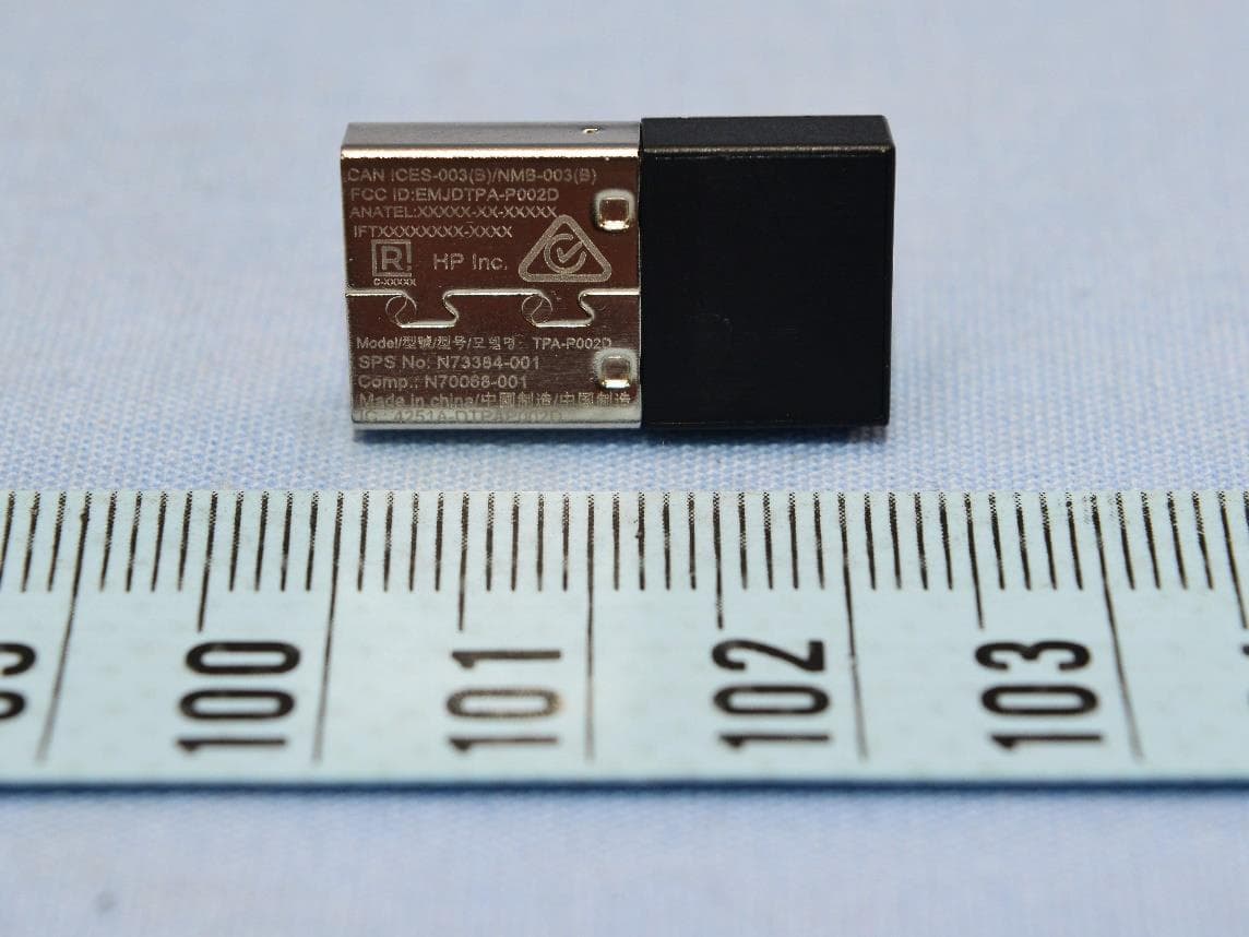
EMJDTPA-P002D
Jan 14, 2024Dongle
Equipment Class
DXX - Part 15 Low Power Communication Device Transmitter
EMJOH1
Oct 29, 2023Level Bridge
Equipment Class
DTS - Digital Transmission System