EMJMMOEMUOA700 BT Gaming Mouse
Primax Electronics Ltd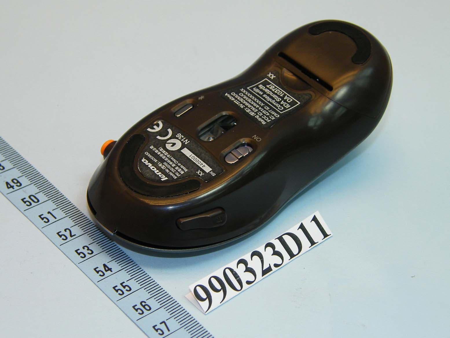
Click to zoom
Application Details
- Equipment Class
- DSS - Part 15 Spread Spectrum Transmitter
- Date of Grant
- Apr 07, 2010
- Application Purpose
- Original Equipment
- Date of Application
- Apr 07, 2010
- Equipment Note
- A700 BT Gaming Mouse
- Frequency Range
- 2402.00000000 - 2480.00000000
- Company
- Primax Electronics Ltd
- Country
- Taiwan
Documents & Files
Document Text
Text extracted from the exhibit documents filed with the FCC. Open a document above to read the original.
Users Manual
Lenovo A700 Series 3-in-1 Mouse User Manual Announcement Thank you for choosing Lenovo products. Please read the information included in the product package thoroughly and carefully before you first install and use this product, which will help you use the product better. Lenovo (Beijing) Ltd. will not be liable for any damages caused by your failure to follow the instructions and requirements herein or by any misoperation of this product due to your misunderstanding of the content of this manual. Lenovo (Beijing) Ltd. has emended and checked the document strictly, but we do not assure that there is no error or oversight. The pictures in this manual are for your reference purpose only. If any of them are different from the actual product, please refer to the actual product. In order to provide better services, Lenovo (Beijing) Ltd. reserves the right to improve and / or modify the product and the software program described in this manual and its content without notice. Lenovo (Beijing) Ltd. will not be responsible for any data loss caused by malfunction of hardware and software, product maintenance, or other situations; nor will we be responsible for associated indirect loss. Please backup your data normally. If you find during the usage the actual product is different from this manual, or you want to get the update information, or you have any question or concern, please visit: Lenovo website: http://www.lenovo.com The content of this manual is protected by the law of copyright. Without a written authorization from Lenovo (Beijing) Ltd., you cannot copy, excerpt, transmit through wired or wireless networks, or translate the manual into any other language. The content of this manual is subject to change without notice. are either trademarks or registered trademarks of Lenovo (Beijing) Limited and/or its affliates. Microsoft and its identification, as well as Windows, Windows 2000, Windows XP, Windows Vista, Windows 7, Windows Media are either registered trademarks or trademarks of Microsoft Corporation in the United States and/or other countries/ territories. Other products or services, brands and trade names mentioned in this manual are either trademarks or registered trademarks of Lenovo or their respective owner. Copyright © 2010 Lenovo (Beijing) Limited. All rights reserved. 2 A700 3-in-1 Mouse User Manual Contents Mouse Blusetooth Connection Guide .........................3 Mouse Usage Mode .....................................................7 Mouse Functions and Status .....................................10 (Motion Drive Game Zone) Game Platform ...............12 Cautions ......................................................................20 Troubleshooting ..........................................................20 3 A700 3-in-1 Mouse User Manual Insert the batteries properly as shown in the diagram. Ensure correct battery polarity. Make sure the one-in-all device is off. Switch the power switch to “ON”. Mouse Blusetooth Connection Guide Prior to the first use, the mouse and the All-In-One PC are in the factory backup status. 4 A700 3-in-1 Mouse User Manual The green light on the front end flashes, indicating the mouse starts the matching process. 1. Press the connect button The green light on the front end flashes, indicating the mouse starts the matching process. After the mouse enters the matching state, the following search and connection process must be completed with ten minutes and otherwise the mouse will enter the sleep mode. Tur n on the computer and it will automatically search the bluetooth device. Once the system window is entered, the mouse will be ready to use. If the mouse is unable to work properly, or it needs to re-connect the PC, you can follow the following steps for mouse connection. 5 A700 3-in-1 Mouse User Manual 2. Search for Bluetooth devices Click the “Bluetooth” icon on the system toolbar and select “Add device” option. The system automatically starts searching for Bluetooth devices. 3. The wireless device “Lenovo Motion Drive Mouse” appears in the list of wireless devices, indicating that the system has found the mouse device. Click this icon and then “Next” to continue the Bluetooth matching operation. 6 A700 3-in-1 Mouse User Manual 4. When the icon “This device has been successfully added to this computer” is displayed. Click “Close” to finish the matching. Now the red light on the front end of the mouse keeps on constantly, which indicates the connection of the mouse to the All-In-One PC is successful and the mouse can work normally. When the Bluetooth connection is established, you need not press again the connect button on the mouse; otherwise the matching process will be re- launched. 7 A700 3-in-1 Mouse User Manual Mouse Usage Mode 1. Description of the Mouse Usage Mode (1) Ordinary mouse mode It can be used as an ordinary optical mouse by placing it on the table. (2) Air mouse mode Hold the mouse in the air and it will automatically enter the air mouse state. The air mouse supports the vertical and horizontal use. This diagram shows he vertical grip of the mouse. Buttons A and B function like left and right buttons, respectively. 8 A700 3-in-1 Mouse User Manual In the air mouse mode, you can move the cursor by moving the mouse up, down, left or right in the air. Air mouse mode This diagram shows the horizontal grip of the mouse. Do not block the optical light at the bottom of the mouse by your fingers. 9 A700 3-in-1 Mouse User Manual (3) Game mode The mouse will switch to the game state when you launch the game platform and enter a game. The mouse should be vertically used in this case. Then the left and right buttons cannot be used but replaced by A and B buttons and the joystick. The mouse will enter the sleep mode if there is no operation for three minutes in the power-on status. At this time, the indicator on the front end of the mouse is off, and the optical lens lamp at the bottom of the mouse keeps blinking. By pressing any button …
Text truncated - open the document above for the full version.
Cover Letter(s)
No. 669, Ruey Kuang Road Neihu Taipei, Taiwan, R.O.C. Tel: 883-2-2798-9008 Fax: 886-2-8798-1565 Date: April 6, 2010 Federal Communications Commission Authorization and Evaluation Division Confidentiality Request FCC ID: EMJMMOEMUO Pursuant to Sections 0.457 and 0.459 of the Commission’s Rules, the Applicant hereby requests confidential treatment of information accompanying this Application as outlined below: Schematics Block Diagram The above materials contain trade secrets and proprietary information not customarily released to the public. The public disclosure of these matters might be harmful to the Applicant and provide unjustified benefits to its competitors. The Applicant understands that pursuant to Rule 0.457, disclosure of this Application and all accompanying documentation will not be made before the date of the Grant for this application. Sincerely yours, ------------------------------------------------------------------- C.T. Huang Compliance Dept. / Director Phone: 886-2-2798-9008 ext.1710 Fax: 886-2-8797-1565 Email: [email protected]
Cover Letter(s)
No. 669, Ruey Kuang Road Neihu Taipei, Taiwan, R.O.C. Tel: 883-2-2798-9008 Fax: 886-2-8798-1565 Power of Attorney Date: April 6, 2010 To whom it may concern: We, the undersigned PRIMAX ELECTRONICS LTD. hereby authorize Bureau Veritas Consumer Products Services (H.K.) Ltd., Taoyuan Branch (BV CPS Taoyuan Branch) of Taiwan to act on our behalf in all matters relating to all processes required in the FCC Part 15C approval and any communication needed with the national authority. Any and all acts carried out by BV CPS Taoyuan Branch on our behalf shall have the same effects as acts of our own. If you have any questions regarding the authorization, please don’t hesitate to contact us. Thank you! Sincerely yours, ----------------------------- C.T. Huang Compliance Dept. / Director Phone: 886-2-2798-9008 ext.1710 Fax: 886-2-8797-1565 Email: [email protected]
External Photos
Page: 1
ID Label/Location Info
Label for Bubble Bag * 1 5 m m *35mm Code type : code 128 Auto Scan data : 25010766 SCALE:1:1 25010766 *26MM *22.6MM *24.5MM *33.3MM Rating (额定): 3V 40mA FCC ID: EMJMMOEMUO IC: 4251A-MMOEMUO CMIIT ID: XXXXXXXXXX Model No (型号).: MOEMUO PN: 25010766 制造商:致伸科技股份有限公司 Made in China (中国制造) 1:1 1:1 固定码 SN: 4 4 0 0 0 0 1 N136 XX XX
Internal Photos
Page: 2 Page: 3 Page: 4 Page: 5 Page: 6 Page: 7 Page: 8
Operational Description
FCC ID: EMJMMOEMUO Report No.: RF990323D11 Operational Description The device is a Frequency Hopping device with 79 hopping frequencies. The antenna type is Printed Antenna and there is no antenna connector used. The EUT is a unit that contains a Bluetooth radio module. Bluetooth is a short-range wireless technology operating in the 2.4GHz band. It enables devices to have the ability to form networks and exchange information. The other instruction, please have a look at the user’s manual.
RF Exposure Info
Report No: SA990323D11 1 Report Format Version 3.0.1 RF EXPOSURE REPORT REPORT NO.: SA990323D11 MODEL NO.: MOEMUO ACCORDING: FCC Guidelines for Human Exposure IEEE C95.1 APPLICANT : PRIMAX ELECTRONICS LTD. ADDRESS : No. 669, Ruey Kuang Road, Neihu, Taipei, Taiwan, R.O.C. ISSUED BY : Bureau Veritas Consumer Products Services (H.K.) Ltd., Taoyuan Branch LAB ADDRESS : No. 47, 14th Ling, Chia Pau Tsuen, Lin Kou Hsiang, Taipei Hsien, 244 Taiwan Report No: SA990323D11 2 Report Format Version 3.0.1 Conclusion No Evaluation Required if power is below this threshold: F(GHz) mW Low 2.402 High 2.480 24.58 Maximum measured transmitter power: Pout (dBm) Pout (mW) Conducted Power 0.6 1.1 EIRP Power -2.3 0.6 *Note: The antenna is Printed antenna with -2.89dBi gain Threshold for no SAR evaluation is 24.58mW Transmitter power is 1.1mW Conclusion: No SAR evaluation required since Transmitter Pout is below FCC threshold ---END---
Test Report
Report No.: RF990323D11 1 Report Format Version 3.0.1 FCC TEST REPORT REPORT NO.: RF990323D11 MODEL NO.: MOEMUO RECEIVED: March 23, 2010 TESTED: March 24, 2010 ISSUED: March 30, 2010 APPLICANT: PRIMAX ELECTRONICS LTD. ADDRESS: No. 669, Ruey Kuang Road, Neihu, Taipei, Taiwan, R.O.C. ISSUED BY: Bureau Veritas Consumer Products Services (H.K.) Ltd., Taoyuan Branch LAB LOCATION: No. 47, 14th Ling, Chia Pau Tsuen, Lin Kou Hsiang, Taipei Hsien, 244 Taiwan This test report consists of 41 pages in total. It may be duplicated completely for legal use with the approval of the applicant. It should not be reproduced except in full, without the written approval of our laboratory. The client should not use it to claim product endorsement by TAF or any government agencies. The test results in the report only apply to the tested sample. Report No.: RF990323D11 2 Report Format Version 3.0.1 TABLE OF CONTENTS 1. CERTIFICATION........................................................................................4 2. SUMMARY OF TEST RESULTS...............................................................5 2.1 MEASUREMENT UNCERTAINTY.............................................................6 3. GENERAL INFORMATION........................................................................7 3.1 GENERAL DESCRIPTION OF EUT..........................................................7 3.2 DESCRIPTION OF TEST MODES............................................................8 3.2.1 CONFIGURATION OF SYSTEM UNDER TEST........................................8 3.2.2 TEST MODE APPLICABILITY AND TESTED CHANNEL DETAIL.............9 3.3.3 GENERAL DESCRIPTION OF APPLIED STANDARDS..........................10 3.3.4 DESCRIPTION OF SUPPORT UNITS.....................................................10 4. TEST TYPES AND RESULTS..................................................................11 4.1 CONDUCTED EMISSION MEASUREMENT...........................................11 4.2 RADIATED EMISSION MEASUREMENT................................................11 4.2.1 LIMITS OF RADIATED EMISSION MEASUREMENT.............................11 4.2.2 TEST INSTRUMENTS.............................................................................12 4.2.3 TEST PROCEDURES.............................................................................13 4.2.4 DEVIATION FROM TEST STANDARD....................................................13 4.2.5 TEST SETUP...........................................................................................14 4.2.6 EUT OPERATING CONDITIONS.............................................................14 4.2.7 TEST RESULTS......................................................................................15 4.3 NUMBER OF HOPPING FREQUENCY USED........................................20 4.3.1 LIMIT OF HOPPING FREQUENCY USED..............................................20 4.3.2 TEST INSTRUMENTS.............................................................................20 4.3.3 TEST PROCEDURES.............................................................................20 4.3.4 DEVIATION FROM TEST STANDARD....................................................21 4.3.5 TEST SETUP...........................................................................................21 4.3.6 TEST RESULTS......................................................................................21 4.4 DWELL TIME ON EACH CHANNEL........................................................23 4.4.1 LIMIT OF DWELL TIME USED................................................................23 4.4.2 TEST INSTRUMENTS.............................................................................23 4.4.3 TEST PROCEDURES.............................................................................23 4.4.4 DEVIATION FROM TEST STANDARD....................................................23 4.4.5 TEST SETUP...........................................................................................24 4.4.6 TEST RESULTS......................................................................................24 4.5 CHANNEL BANDWIDTH.........................................................................27 4.5.1 LIMITS OF CHANNEL BANDWIDTH.......................................................27 4.5.2 TEST INSTRUMENTS.............................................................................27 4.5.3 TEST PROCEDURE................................................................................27 4.5.4 DEVIATION FROM TEST STANDARD....................................................28 4.5.5 TEST SETUP...........................................................................................28 4.5.6 EUT OPERATING CONDITION...............................................................28 4.5.7 TEST RESULTS......................................................................................29 Report No.: RF990323D11 3 Report Format Version 3.0.1 4.6 HOPPING CHANNEL SEPARATION.......................................................30 4.6.1 LIMIT OF HOPPING CHANNEL SEPARATION.......................................30 4.6.2 TEST INSTRUMENTS.............................................................................30 4.6.3 TEST PROCEDURES.............................................................................30 4.6.4 DEVIATION FROM TEST STANDARD....................................................30 4.6.5 TEST SETUP...........................................................................................30 4.6.6 TEST RESULTS......................................................................................31 4.7 MAXIMUM PEAK OUTPUT POWER.......................................................32 4.7.1 LIMITS OF MAXIMUM PEAK OUTPUT POWER MEASUREMENT........32 4.7.2 TEST INSTRUMENTS.............................................................................32 4.7.3 TEST PROCEDURES.............................................................................32 4.7.4 DEVIATION FROM TEST…
Text truncated - open the document above for the full version.
Test Setup Photos
1 PHOTOGRAPHS OF THE TEST CONFIGURATION RADIATED EMISSION TEST
Contact Information
Applicant
Nelson Chou(Manager)
Technical Contact
Bureau Veritas CPS (H.K.) Ltd. Taoyuan BranchGary Chang
[email protected]886-3-3183232
No. 19, Hwa Ya 2nd Rd., Kwei Shan Hsiang · Taoyuan Hsien · Taiwan
Non-Technical Contact
Bureau Veritas CPS (H.K.) Ltd. Taoyuan BranchZoe Chang
[email protected]886-3-3183232
Test Firm
Bureau Veritas CPS (H.K.) Ltd. Taoyuan BranchRichard Chen
Technical Specifications
| # | Rule Parts | Frequency Range | Power Output |
|---|---|---|---|
| 1 | 15C | 2.40 GHz - 2.48 GHz | 1.00 mW |
Other Applications from Primax Electronics Ltd
EMJ-BHS2705
Aug 28, 2026Wireless Headset
Equipment Class
DTS - Digital Transmission SystemEMJMMOBTN5O
Aug 22, 2024wegear MW1 Creator Mouse
Equipment Class
DTS - Digital Transmission SystemEMJDDGRFN5
Aug 22, 2024wegear MW1 2.4G Dongle
Equipment Class
DXX - Part 15 Low Power Communication Device Transmitter
EMJDTPA-P002D
Jan 14, 2024Dongle
Equipment Class
DXX - Part 15 Low Power Communication Device Transmitter
EMJOH1
Oct 29, 2023Level Bridge
Equipment Class
DTS - Digital Transmission System