EMJMMORFFEUODynex 2.4GHz Wireless Optical Mouse
Primax Electronics Ltd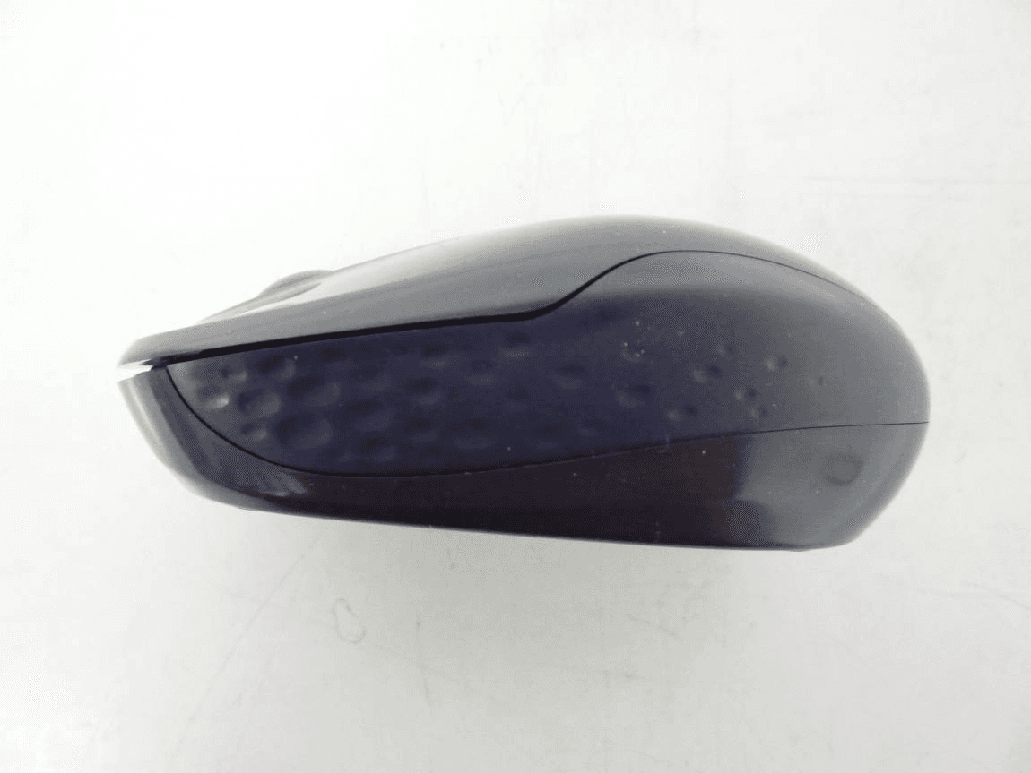
Click to zoom
Application Details
- Equipment Class
- DXX - Part 15 Low Power Communication Device Transmitter
- Date of Grant
- Feb 23, 2011
- Application Purpose
- Original Equipment
- Date of Application
- Feb 15, 2011
- Equipment Note
- Dynex 2.4GHz Wireless Optical Mouse
- Frequency Range
- 2402.00000000 - 2479.00000000
- Company
- Primax Electronics Ltd
- Country
- Taiwan
Documents & Files
Document Text
Text extracted from the exhibit documents filed with the FCC. Open a document above to read the original.
Users Manual
# Component # Component 1 Left button 4 Battery indicator LED 2 Right button 5 Power switch 3 Scroll wheel 6 Optical sensor Quick Setup Guide I DX-NPWLMSE Wireless Optical Mouse Guide d’installation rapide I Souris optique sans fil DX-NPWLMSE Guía de instalación rápida I Ratón óptico inalámbrico DX-NPWLMSE Package contents • 2.4G optical mouse • AA battery (1) • Quick Setup Guide System requirements • Windows® 7, Windows Vista®, Windows® XP, or Mac OS® X 10.4 or later • One available USB port Features Setting up your mouse 1 Open the battery/USB receiver compartment cover as shown. 2 Insert the battery (included), making sure that the + and - on the battery match the + and - in the battery compartment. 3 Close the battery/USB receiver compartment cover. 4 Plug the USB receiver into an available USB port on your computer. 5 Switch the power button on the bottom of the mouse to the ON position. Your computer automatically detects the mouse. Using your mouse 1 Press the left and right mouse buttons to perform standard left and right button functions. 2 Use the scroll wheel to scroll up and down the screen. 3 Press and hold the scroll wheel down, then move the mouse up and down to scroll up and down the screen. Note: This feature may not be available in all programs. Battery indicator LED • The LED indicator lights green for three seconds and then it turns off when the mouse is switched on and pairing is established. • The LED indicator flashes red when the battery level is low. Replace the battery immediately. Cleaning your mouse • Wipe the mouse with a damp, lint-free cloth. Troubleshooting • Make sure that your computer meets the system requirements. • Only use the mouse on a clean, flat, non-slippery surface to ensure smooth and accurate cursor action. • If your computer BIOS setup has mouse options, make sure that they are set to default settings. • If your mouse fails to work, check the USB mouse function in your computer BIOS. The function should be enabled for normal use. FCC statement This device complies with Part 15 of the FCC Rules. Operation is subject to the following two conditions: (1) this device may not cause harmful interference, and (2) this device must accept any interference received, including interference that may cause undesired operation. You are cautioned that changes or modifications not expressly approved by the part responsible for compliance could void the user’s authority to operate the equipment. Class B digital device or peripheral, refer to FCC Part 15.105 (b) FCC ID: EMJMMORFFEUO IC: 4251A-MMORFFEUO IC-RSS210 statement This device complies with Industry Canada licence exempt RSS standard(s). Operation is subject to the following two conditions: (1) this device may not cause interference, and (2) this device must accept any interference, including interference that may cause undesired operation of the device. Le présent appareil est conforme aux CNR d'Industrie Canada applicables aux appareils radio exempts de licence. L'exploitation est autorisée aux deux conditions suivantes : (1) l'appareil ne doit pas produire de brouillage, et (2) l'utilisateur de l'appareil doit accepter tout brouillage radioélectrique subi, même si le brouillage est susceptible d'en compromettre le fonctionnement. ICES-003 statement This Class B digital apparatus complies with Canadian ICES-003; Cet appareil numérique de la classe B est conforme à la norme NMB-003 du Canada. One-year limited warranty For complete warranty, visit www.dynexproducts.com. Contact Dynex: For customer service call 1-800-305-2204 www.dynexproducts.com © 2011 BBY Solutions, Inc. All Rights Reserved. DYNEX is a trademark of BBY Solutions, Inc. Registered in some countries. All other products and brand names are trademarks of their respective owners. ONOFF ONOFF N° Composant N° Composant 1 Bouton gauche 4 Témoin DEL de la pile 2 Bouton droit 5 Interrupteur marche-arrêt 3 Molette de défilement 6 Capteur optique ONOFF ONOFF Contenu de l’emballage • Souris optique 2,4 GHz • Pile AA (1) • Guide d’installation rapide Configuration système requise • Windows MD 7, Windows Vista MD , Windows MD XP et Mac OS MD X 10.4 ou supérieur • Un port USB disponible Caractéristiques Configuration de la souris 1 Ouvrir le couvercle du compartiment de la pile/du récepteur USB tel qu’illustré. 2 Insérer la pile (fournie), en vérifiant que les pôles + et - de la pile coïncident avec les repères + et - figurant à l’intérieur du compartiment. 3 Fermer le couvercle du compartiment de la pile/du récepteur USB. 4 Brancher le récepteur USB sur un port USB de l’ordinateur. 5 Mettre le bouton marche/arrêt situé sur la partie inférieure de la souris sur ON (Marche). L’ordinateur détecte automatiquement la souris. Utilisation de la souris 1 Appuyer sur les boutons gauche et droit de la souris pour obtenir les fonctions classiques de ces boutons. 2 Utiliser la molette de défilement pour faire défiler l’écran vers le haut ou vers le bas. 3 Maintenir la molette de défilement appuyée, puis déplacer la souris vers le haut ou vers le bas pour faire défiler l’écran dans les deux sens. Remarque : Cette fonctionnalité peut ne pas être disponible dans toutes les applications. Témoin DEL de la pile • Le témoin DEL s'allume en vert pendant trois secondes, puis s'éteint quand la souris est activée et que la connexion est établie. • Le témoin DEL clignote en rouge quand le niveau de la pile est faible. Remplacer les piles immédiatement. Nettoyage de la souris • Essuyer la souris avec un chiffon humide non-pelucheux. Problèmes et solutions • Vérifier que l’ordinateur est conforme aux spécifications requises du système. • Utiliser la souris uniquement sur une surface propre, plane et non-glissante pour assurer un mouvement régulier et précis du curseur. • Si la configuration du BIOS de l’ordinateur comporte des options pour la souris, vérifier qu'elles sont réglées en fonction des paramètres par défaut. • Si la souris ne fonctionne pas, vérifier que la foncti…
Text truncated - open the document above for the full version.
External Photos
Page 1 of 3 Type Designation: DX-NPWLMSE Report Number: 17019069 001 Fig. 1: External view Fig. 2: External view Page 2 of 3 Type Designation: DX-NPWLMSE Report Number: 17019069 001 Page 3 of 3 Type Designation: DX-NPWLMSE Report Number: 17019069 001
ID Label/Location Info
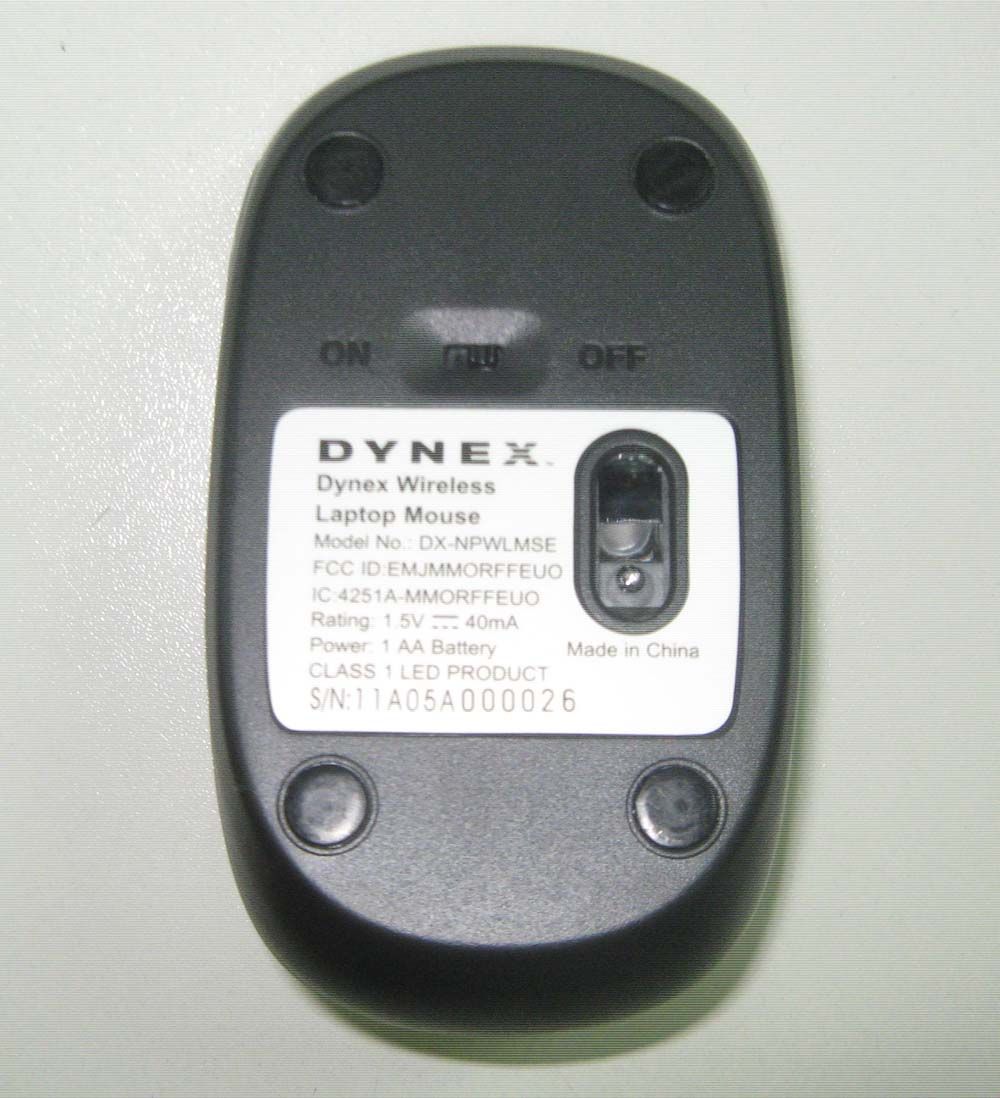
Dynex Wired Optical Mouse Model No.: DX-NPMSE Rating: 5V 100mA Made in China S/N:YYMDDAXXXXXX This Class [B] digital apparatus complies with Canadian ICES-003 Cet appareil numrique de la classe [B] est conforme la norme NMB-003 du Canada. é à Dynex 2.4G Wireless Optical Mouse Model No.: DX-NPWLMSE FCC ID:EMJMMORFFEUO IC:4251A-MMORFFEUO Rating: 1.5V 40mA Power: 1 AA Battery Made in China CLASS 1 LED PRODUCT S/N:YYMDDAXXXXXX *43 mm * 2 4 . 5 m m *40.9 mm * 2 8 . 5 m m Model No.:DX-NPWLMSEA FCC ID:EMJDMORFF3UO IC:4251A-DMORFF3UO S/N:XXXXXXXXXX
Internal Photos
Page 1 of 2 Type Designation: DX-NPWLMSE Report Number: 17019069 001 Page 2 of 2 Type Designation: DX-NPWLMSE Report Number: 17019069 001
Test Report
Produkte Products Prüfbericht - Nr.: Test Report No. 17019069 001 Seite 2 von 25 Page 2 of 25 TEST SUMMARY 5.1.1 ANTENNA REQUIREMENT RESULT: Passed 5.1.2 FIELD STRENGTH OF FUNDAMENTAL AND HARMONICS RESULT: Passed 5.1.3 20DB BANDWIDTH RESULT: Passed 5.1.4 99% BANDWIDTH RESULT: Passed 5.1.5 OUT OF BAND EMISSION RESULT: Passed 5.1.6 RADIATED EMISSION RESULT: Passed 6.1.1 ELECTROMAGNETIC FIELDS RESULT: Passed Produkte Products Prüfbericht - Nr.: Test Report No. 17019069 001 Seite 3 von 25 Page 3 of 25 Contents 1. GENERAL REMARKS......................................................................................................... 4 1.1 COMPLEMENTARY MATERIALS.......................................................................................... 4 2. TEST SITES...................................................................................................................... 4 2.1 TEST FACILITIES............................................................................................................... 4 2.2 LIST OF TEST AND MEASUREMENT INSTRUMENTS............................................................... 5 2.3 TRACEABILITY.................................................................................................................. 5 2.4 CALIBRATION................................................................................................................... 6 2.5 MEASUREMENT UNCERTAINTY........................................................................................... 6 2.6 LOCATION OF ORIGINAL DATA........................................................................................... 6 2.7 STATUS OF FACILITY USED FOR TESTING........................................................................... 6 3. GENERAL PRODUCT INFORMATION.................................................................................... 7 3.1 PRODUCT FUNCTION AND INTENDED USE........................................................................... 7 3.2 RATINGS AND SYSTEM DETAILS........................................................................................ 7 3.3 INDEPENDENT OPERATION MODES.................................................................................... 8 3.4 NOISE GENERATING AND NOISE SUPPRESSING PARTS....................................................... 8 3.5 SUBMITTED DOCUMENTS.................................................................................................. 8 4. TEST SET-UP AND OPERATION MODES.............................................................................. 9 4.1 PRINCIPLE OF CONFIGURATION SELECTION........................................................................ 9 4.2 TEST OPERATION AND TEST SOFTWARE............................................................................ 9 4.3 SPECIAL ACCESSORIES AND AUXILIARY EQUIPMENT.......................................................... 9 4.4 COUNTERMEASURES TO ACHIEVE EMC COMPLIANCE......................................................... 9 4.5 TEST SETUP DIAGRAM.................................................................................................... 10 5. TEST RESULTS............................................................................................................... 12 5.1 TRANSMITTER REQUIREMENT & TEST SUITES.................................................................. 12 5.1.1 Antenna Requirement ................................................................................................................12 5.1.2 Field strength of fundamental and harmonics............................................................................13 5.1.3 20dB Bandwidth .........................................................................................................................14 5.1.4 99% Bandwidth ..........................................................................................................................17 5.1.5 Out of band emission .................................................................................................................20 5.1.6 Radiated emission......................................................................................................................21 6. SAFETY HUMAN EXPOSURE............................................................................................. 22 6.1 RADIO FREQUENCY EXPOSURE COMPLIANCE................................................................... 22 6.1.1 Electromagnetic Fields ...............................................................................................................22 7. PHOTOGRAPHS OF THE TEST SET-UP.............................................................................. 23 8. LIST OF TABLES............................................................................................................. 25 9. LIST OF PHOTOGRAPHS.................................................................................................. 25 Produkte Products Prüfbericht - Nr.: Test Report No. 17019069 001 Seite 4 von 25 Page 4 of 25 1. General Remarks 1.1 Complementary Materials All attachments are integral parts of this test report. This applies especially to the following appendix: Appendix 1: Test Result of Radiated Emissions 2. Test Sites 2.1 Test Facilities TÜV Rheinland (Guangdong) Ltd. EMC Laboratory Guangzhou Auto Market, Yuan Gang Section of Guangshan Road, Guangzhou, P.R. China FCC Registration No.: 833845 Test site Industry Canada No.: 2932C-1 Produkte Products Prüfbericht - Nr.: Test Report No. 17019069 001 Seite 5 von 25 Page 5 of 25 2.2 List of Test and Measurement Instruments Table 1: List of Test and Measurement Equipment Kind of Equipment Manufacturer Type S/N Calibrated until Spurious emission and Radiated emission EMI Test Receiver Rohde & Schwarz ESCI-3 100216 2011-11-26 Spectrum Analyzer Rohde & Schwarz FSP30 100286 2011-08-24 Trilog-Broadband Antenna SCHWARZBECK MESS-ELEKTRONIK VULB9168 209 2011-11-07 Double-Ridged Wavegui…
Text truncated - open the document above for the full version.
Test Setup Photos
Produkte Products Prüfbericht - Nr.: Test Report No. 17019069 001 Seite 23 von 25 Page 23 of 25 7. Photographs of the Test Set-Up Photograph 1: Set-up for Radiated Emissions (9kHz - 30MHz) Photograph 2: Set-up for Radiated Emissions (30MHz-1GHz) Produkte Products Prüfbericht - Nr.: Test Report No. 17019069 001 Seite 24 von 25 Page 24 of 25 Photograph 3: Set-up for Radiated Emissions (1GHz-18GHz) Photograph 4: Set-up for Radiated Emissions (18GHz-25GHz)
Contact Information
Applicant
Nelson Chou(Manager)
Test Firm
TUV Rheinland (GuangDong) Ltd.Yuxin Huang
Technical Specifications
| # | Rule Parts | Frequency Range | Power Output |
|---|---|---|---|
| 1 | 15C | 2.40 GHz - 2.48 GHz | - |
Other Applications from Primax Electronics Ltd
EMJ-BHS2705
Aug 28, 2026Wireless Headset
Equipment Class
DTS - Digital Transmission SystemEMJMMOBTN5O
Aug 22, 2024wegear MW1 Creator Mouse
Equipment Class
DTS - Digital Transmission SystemEMJDDGRFN5
Aug 22, 2024wegear MW1 2.4G Dongle
Equipment Class
DXX - Part 15 Low Power Communication Device Transmitter
EMJDTPA-P002D
Jan 14, 2024Dongle
Equipment Class
DXX - Part 15 Low Power Communication Device Transmitter
EMJOH1
Oct 29, 2023Level Bridge
Equipment Class
DTS - Digital Transmission System