EMJRSP800101Nano Remote Control
Primax Electronics Ltd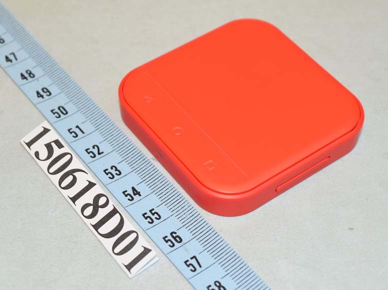
Click to zoom
Application Details
- Equipment Class
- DTS - Digital Transmission System
- Date of Grant
- Aug 09, 2015
- Application Purpose
- Original Equipment
- Date of Application
- Aug 09, 2015
- Equipment Note
- Nano Remote Control
- Frequency Range
- 2402.00000000 - 2480.00000000
- Company
- Primax Electronics Ltd
- Country
- Taiwan
Documents & Files
Document Text
Text extracted from the exhibit documents filed with the FCC. Open a document above to read the original.
Users Manual
QUICK START GUIDE Sharing your screen with your SlimPort NANO·CONSOLE is as easy as using your phone. Use this quick start guide to begin. WELCOME TO YOUR 2 HERE’S WHAT COMES WITH YOUR NANO·CONSOLE. Base Tower NANO Remote Battery Tray (Inside the remote) Batteries (2) Type: CR2032 3V (located inside the remote) HDMI Cable Micro-USB Charging Cable 3 SETTING UP YOUR NANO·CONSOLE Your NANO·CONSOLE is designed to hold your device as it connects to larger displays. One side of the base has a raised lip. Attach the tower to the base so the writing on the top of the tower (“SlimPort NANO·CONSOLE”) reads from left to right when aligned with the lip. The NANO Remote is designed to rest on the surface of the tower. See page 8 for more information on how to use the NANO Remote. Raised Lip 4 CONNECTING YOUR DEVICE TO THE NANO·CONSOLE Plug the Micro-USB connector that is permanently attached to the NANO·CONSOLE into the Micro-USB port on your SlimPort-enabled device. Tip: You can also charge your device by plugging the provided untethered Micro-USB cable into the NANO·CONSOLE and then into your device’s USB wall charger as normal. 5 CONNECTING YOUR NANO·CONSOLE TO YOUR TV OR MONITOR Connect your NANO·CONSOLE by running an HDMI cable from the HDMI OUT port on the NANO·CONSOLE to an HDMI IN port on your big screen. To your device’s wall charger or USB port on your TV Tip: The NANO·CONSOLE includes an auxiliary port you can use to connect other devices that have a high-definition video output to your TV or monitor as needed. However, when a SlimPort- enabled device and another device are both plugged in, the NANO·CONSOLE will select the video from the SlimPort-enabled device to show on the big screen. SlimPort-enabled Device Other Device 6 SEEING YOUR SMALL SCREEN ON THE BIG SCREEN Set the input on your TV or monitor to the HDMI port the NANO·CONSOLE is connected to. After a few moments, the device’s screen should now be visible on the TV or monitor. TV AV HDMI PC INPUT SETTING 7 The NANO Remote is how you interact with your device on the big screen. It’s designed to mimic the experience of using your device in your hand. YOUR NANO REMOTE Main Touchpad Back Button Home Button Recent Apps Button Note: If your device is not running Android 5.1 or later, the Recent Apps button will not do anything when you press it. LED Light (2) Batteries Type: CR2032 3V (located inside the remote) Battery Tray +/- Volume Button Battery Tray 8 SETTING UP YOUR NANO REMOTE The NANO Remote comes with two CR2032 coin batteries. To activate the batteries and power the remote, pull the plastic tab sticking out of the battery tray. This allows the batteries to power the remote. Note: You should not need to remove the tray for this. PULL TAB Note: There is no on/off switch on the NANO Remote; the remote will automatically go into sleep mode after 3 minutes of inactivity. It will wake up when you click on the touchpad. 9 CHANGING YOUR NANO REMOTE’S BATTERIES When you need to replace the batteries, remove the tray, discard the old batteries and fit new ones into the tray with the + side facing down. The battery tray only fits into the remote one way. If you try and put the battery tray in upside-down it will not slide in easily. Note: With average use, the batteries should last approximately 3 months before needing to be replaced. 10 CONNECTING THE NANO REMOTE TO YOUR DEVICE The NANO Remote connects to your device via a version of Bluetooth ® called, Bluetooth Smart (also referred to as Bluetooth Low Energy). Once the batteries have been installed, hold the volume + button and the touchpad button simultaneously for 3 seconds. The LED light on the remote will begin to blink. The remote is now Bluetooth discoverable. Note: If your device’s hardware or operating system does not support Bluetooth Smart, it will not be able to connect with the NANO Remote. NANO.CONSOLE Remote Wireless Keyboard My Computer BLUETOOTH SETTINGS NANO.CONSOLE Remote Wireless Keyboard My Computer BLUETOOTH SETTINGS Next, go to your device’s settings panel and turn on Bluetooth. Wait a moment and the remote will show up as “NANO·CONSOLE Remote”. Select the remote to connect and your remote will be connected to your device. You can now start using your NANO Remote to control your device. 11 USING THE VOLUME BUTTON The +/- Volume Button on the right side of your NANO Remote allows you to increase and lower the volume of your audio out from your phone. Tip: Depending on your device manufacturer and the version of Android you are using, pressing the Volume Button will increase and decrease volume a little bit at a time, or it can turn on sound or mute the sound. Fun tip: When using the standard Android camera app, pressing “+” on the Volume Button will take a picture. Your NANO Remote can be used as a selfie remote! 12 GETTING THE HANG OF THE NANO REMOTE The touchpad of the remote works like the screen of your device. When using the remote, a cursor will indicate where your finger would be on the screen. Click the main touchpad to reproduce a tap, click and hold to drag items and scroll through documents and screens. Take a moment to practice clicking, dragging items, navigating from one screen to another and scrolling through documents. Using apps you’re familiar with should shorten the learning curve a bit. Fun fact: Our favorite way of learning the finer points of clicking, dragging and manipulating objects with the NANO Remote is playing Angry Birds! 13 THE LED LIGHT ON YOUR NANO REMOTE The LED light on the front of your NANO Remote will blink several different ways to communicate different things. - When the remote is woken up, it will blink once - When the remote is in pairing mode, it will blink for 2 minutes - When the remote’s batteries are low, it will blink rapidly for 3 seconds every time you wake it up NANO.CONSOLE Remote Wireless Keyboard My Computer BLUETOOTH SETTINGS 14 TROUBLESHOOTING If your device screen does not appear on the TV or monitor: • Ch…
Text truncated - open the document above for the full version.
Cover Letter(s)
No. 669, Ruey Kuang Road Neihu Taipei, Taiwan, R.O.C. Tel: 883-2-2798-9008 Fax: 886-2-8798-1565 Date: 2015-07-28 FCC ID: EMJRSP800101 AUTHORIZATION LETTER To whom it may concern: We, the undersigned, hereby authorize Amanda Wu / Senior Specialist of Bureau Veritas Consumer Products Services (H.K.) Ltd., Taoyuan Branch (BV CPS Taoyuan) of Taiwan to act on our behalf in all manners relating to FCC application for equipment authorization, including signing of all documents relating to these matters. Any and all acts carried out by Amanda Wu / Senior Specialist of BV CPS Taoyuan on our behalf shall have the same effect as acts of our own. If you have any questions regarding the authorization, please don’t hesitate to contact us. Sincerely yours, ------------------------------------------------------------------- C.T. Huang Compliance Dept. / Director Phone: 886-2-2798-9008 ext.1710 Fax: 886-2-8797-1565 Email: [email protected]
Cover Letter(s)
No. 669, Ruey Kuang Road Neihu Taipei, Taiwan, R.O.C. Tel: 883-2-2798-9008 Fax: 886-2-8798-1565 Date: July 28, 2015 Federal Communications Commission Authorization and Evaluation Division Confidentiality Request FCC ID: EMJRSP800101 Pursuant to Sections 0.457 and 0.459 of the Commission’s Rules, the Applicant hereby requests confidential treatment of information accompanying this Application as outlined below: Schematics Block Diagram The above materials contain trade secrets and proprietary information not customarily released to the public. The public disclosure of these matters might be harmful to the Applicant and provide unjustified benefits to its competitors. The Applicant understands that pursuant to Rule 0.457, disclosure of this Application and all accompanying documentation will not be made before the date of the Grant for this application. Sincerely yours, ------------------------------------------------------------------- C.T. Huang Compliance Dept. / Director Phone: 886-2-2798-9008 ext.1710 Fax: 886-2-8797-1565 Email: [email protected]
Cover Letter(s)
No. 669, Ruey Kuang Road Neihu Taipei, Taiwan, R.O.C. Tel: 883-2-2798-9008 Fax: 886-2-8798-1565 Date: 2015-08-07 FCC ID: EMJRSP800101 To the attention of Federal Communications Commission Authorization and Evaluation Division Confidentiality Request Pursuant to Sections 0.457 and 0.459 of the commission’s rules, we request short-term confidential treatment for the following information until 2015/9/30 in order to ensure sensitive business information remains confidential until the actual marketing of the device: External photos Test Setup photos User’s manual Internal Photos Sincerely yours, ------------------------------------------------------------------- C.T. Huang Compliance Dept. / Director Phone: 886-2-2798-9008 ext.1710 Fax: 886-2-8797-1565 Email: [email protected]
External Photos
Page 1 CONSTRUCTION PHOTOS OF EUT
ID Label/Location Info
IC:4251A-RSP800101 CMIT ID:2015DJ3248 FCC ID:EMJRSP800101 CCAIXXXXXXXXX KCC:MSIP-CRM- PMX-RSP800101 R Z571 For all World NANO Remote/摇控器/搖控器 Rating/额定/額定: 3V===30mA Model/型号/型號: SP8001-01 Designed in California by Analogix Semiconductor, Inc. Made in China/中国制造/中國製造 Back of EUT
Internal Photos
Page 2 Page 3 Page 4 Page 5 Page 6
RF Exposure Info
Report No.: SA150713D06 Page No. 1 / 6 Report Format Version: 6.1.1 RF Exposure Report Report No.: SA150713D06 FCC ID: EMJRSP800101 Test Model: SP8001-01 Received Date: Jul. 13, 2015 Test Date: Jul. 13, 2015 Issued Date: Jul. 21, 2015 Applicant: PRIMAX ELECTRONICS LTD. Address: No. 669, Ruey Kuang Road, Neihu, Taipei, Taiwan, R.O.C. Issued By: Bureau Veritas Consumer Products Services (H.K.) Ltd., Taoyuan Branch Lab Address: No. 47-2, 14th Ling, Chia Pau Vil., Lin Kou Dist., New Taipei City, Taiwan ( R.O.C. ) This report is for your exclusive use. Any copying or replication of this report to or for any other person or entity, or use of our name or trademark, is permitted only with our prior written permission. This report sets forth our findings solely with respect to the test samples identified herein. The results set forth in this report are not indicative or representative of the quality or characteristics of the lot from which a test sample was taken or any similar or identical product unless specifically and expressly noted. Our report includes all of the tests requested by you and the results thereof based upon the information that you provided to us. You have 60 days from date of issuance of this report to notify us of any material error or omission caused by our negligence, provided, however, that such notice shall be in writing and shall specifically address the issue you wish to raise. A failure to raise such issue within the prescribed time shall constitute your unqualified acceptance of the completeness of this report, the tests conducted and the correctness of the report contents. Unless specific mention, the uncertainty of measurement has been explicitly taken into account to declare the compliance or non-compliance to the specification. The report must not be used by the client to claim product certification, approval, or endorsement by TAF or any government agencies. Report No.: SA150713D06 Page No. 2 / 6 Report Format Version: 6.1.1 Table of Contents Release Control Record .................................................................................................................................. 3 1 Certificate of Conformity ...................................................................................................................... 4 2 Evaluation Result .................................................................................................................................. 5 3 Sar Test Exclusion Thresholds ........................................................................................................... 6 4 Conclusion ............................................................................................................................................ 6 Report No.: SA150713D06 Page No. 3 / 6 Report Format Version: 6.1.1 Release Control Record Issue No. Description Date Issued SA150713D06 Original release Jul. 21, 2015 Report No.: SA150713D06 Page No. 4 / 6 Report Format Version: 6.1.1 1 Certificate of Conformity Product: Nano Remote Control Brand: PRIMAX Test Model: SP8001-01 Sample Status: Engineering Sample Applicant: PRIMAX ELECTRONICS LTD. Test Date: Jul. 13, 2015 Standards: FCC Part 2 (Section 2.1093) KDB 447498 D03 IEEE C95.1 The above equipment has been tested by Bureau Veritas Consumer Products Services (H.K.) Ltd., Taoyuan Branch, and found compliance with the requirement of the above standards. The test record, data evaluation & Equipment Under Test (EUT) configurations represented herein are true and accurate accounts of the measurements of the sample’s EMC characteristics under the conditions specified in this report. Prepared by : , Date:Jul. 21, 2015 Annie Chang / Supervisor Approved by : , Date:Jul. 21, 2015 Rex Lai / Assistant Manager Report No.: SA150713D06 Page No. 5 / 6 Report Format Version: 6.1.1 2 Evaluation Result Following FCC KDB 447498 D01 “General SAR test exclusion guidance” The corresponding SAR Exclusion Threshold condition, listed below: 1) The 1-g and 10-g SAR test exclusion thresholds for 100 MHz to 6 GHz at test separation distances ≤ 50 mm are determined by: [(max. power of channel, including tune-up tolerance, mW)/(min. test separation distance, mm)] ·[√f(GHz)] ≤ 3.0 for 1-g SAR and ≤ 7.5 for 10-g extremity SAR, where f(GHz) is the RF channel transmit frequency in GHz . Power and distance are rounded to the nearest mW and mm before calculation . The result is rounded to one decimal place for comparison The test exclusions are applicable only when the minimum test separation distance is ≤ 50 mm and for transmission frequencies between 100 MHz and 6 GHz. When the minimum test separation distance is < 5 mm, a distance of 5 mm is applied to determine SAR test exclusion. 2) At 100 MHz to 6 GHz and for test separation distances > 50 mm, the SAR test exclusion threshold is determined according to the following: a) [Threshold at 50 mm in step 1) + (test separation distance - 50mm)·( f(MHz)/150)] mW, at 100MHz to 1500 MHz b) [Threshold at 50 mm in step 1) + (test separation distance - 50 mm)·10] mW at > 1500 MHz and ≤ 6 GHz 3) At frequencies below 100 MHz, the following may be considered for SAR test exclusion. a) The threshold at the corresponding test separation distance at 100 MHz in step 2) is multiplied by [1 + log(100/f(MHz))] for test separation distances > 50 mm and < 200 mm. b) The threshold determined by the equation in a) for 50 mm and 100 MHz is multiplied by ½ for test separation distances ≤ 50 mm. c) SAR measurement procedures are not established below 100 MHz. When SAR test exclusion cannot be applied, a KDB inquiry is required to determine SAR evaluation requirements for any test results to be acceptable. Report No.: SA150713D06 Page No. 6 / 6 Report Format Version: 6.1.1 3 SAR Test Exclusion Thresholds Maximum measured transmitter power: Frequency (GHz) Max. Power (mW) Min. test separation distance (mm) SAR test exclusion calculation value (NOTE 2) 1-g SAR test exclusion thresholds R…
Text truncated - open the document above for the full version.
Test Report
Report No.: RF150713D06 Page No. 1 / 29 Report Format Version: 6.1.1 FCC Test Report Report No.: RF150713D06 FCC ID: EMJRSP800101 Test Model: SP8001-01 Received Date: Jul. 13, 2015 Test Date: Jul. 13, 2015 Issued Date: Jul. 21, 2015 Applicant: PRIMAX ELECTRONICS LTD. Address: No. 669, Ruey Kuang Road, Neihu, Taipei, Taiwan, R.O.C. Issued By: Bureau Veritas Consumer Products Services (H.K.) Ltd., Taoyuan Branch Lab Address: No. 47-2, 14th Ling, Chia Pau Vil., Lin Kou Dist., New Taipei City, Taiwan (R.O.C.) This report is for your exclusive use. Any copying or replication of this report to or for any other person or entity, or use of our name or trademark, is permitted only with our prior written permission. This report sets forth our findings solely with respect to the test samples identified herein. The results set forth in this report are not indicative or representative of the quality or characteristics of the lot from which a test sample was taken or any similar or identical product unless specifically and expressly noted. Our report includes all of the tests requested by you and the results thereof based upon the information that you provided to us. You have 60 days from date of issuance of this report to notify us of any material error or omission caused by our negligence, provided, however, that such notice shall be in writing and shall specifically address the issue you wish to raise. A failure to raise such issue within the prescribed time shall constitute your unqualified acceptance of the completeness of this report, the tests conducted and the correctness of the report contents. Unless specific mention, the uncertainty of measurement has been explicitly taken into account to declare the compliance or non-compliance to the specification. The report must not be used by the client to claim product certification, approval, or endorsement by TAF or any government agencies. Report No.: RF150713D06 Page No. 2 / 29 Report Format Version: 6.1.1 Table of Contents Release Control Record .................................................................................................................................. 4 1 Certificate of Conformity ...................................................................................................................... 5 2 Summary of Test Results ..................................................................................................................... 6 2.1 Measurement Uncertainty ................................................................................................................... 6 2.2 Modification Record ............................................................................................................................ 6 3 General Information .............................................................................................................................. 7 3.1 General Description of EUT ................................................................................................................ 7 3.2 Description of Test Modes ................................................................................................................... 8 3.2.1 Test Mode Applicability and Tested Channel Detail ............................................................................. 9 3.3 Duty Cycle Of Test Signal ................................................................................................................. 10 3.4 Description of Support Units .............................................................................................................. 11 3.4.1 Configuration of System under Test ................................................................................................... 11 3.5 General Description of Applied Standards ........................................................................................ 12 4 Test Types and Results ...................................................................................................................... 13 4.1 Radiated Emission and Bandedge Measurement ............................................................................. 13 4.1.1 Limits of Radiated Emission and Bandedge Measurement .............................................................. 13 4.1.2 Test Instruments ................................................................................................................................ 14 4.1.3 Test Procedures ................................................................................................................................. 15 4.1.4 Deviation from Test Standard ............................................................................................................ 15 4.1.5 Test Set Up ........................................................................................................................................ 16 4.1.6 EUT Operating Conditions ................................................................................................................. 16 4.1.7 Test Results ....................................................................................................................................... 17 4.2 6dB Bandwidth Measurement ........................................................................................................... 21 4.2.1 Limits of 6dB Bandwidth Measurement ............................................................................................. 21 4.2.2 Test Setup .......................................................................................................................................... 21 4.2.3 Test Instruments ................................................................................................................................ 21 4.2.4 Test Procedure .................................................................................................................................. 21 4.2.5 Deviation fromTest St…
Text truncated - open the document above for the full version.
Test Setup Photos
1 of 1 PHOTOGRAPHS OF THE TEST CONFIGURATION Radiated Emission Test
Contact Information
Applicant
Nelson Chou(Manager)
Test Firm
Bureau Veritas CPS (H.K.) Ltd., Taoyuan BranchRichard Chen
Technical Specifications
| # | Rule Parts | Frequency Range | Power Output |
|---|---|---|---|
| 1 | 15C | 2.40 GHz - 2.48 GHz | 1.00 mW |
Other Applications from Primax Electronics Ltd
EMJ-BHS2705
Aug 28, 2026Wireless Headset
Equipment Class
DTS - Digital Transmission SystemEMJMMOBTN5O
Aug 22, 2024wegear MW1 Creator Mouse
Equipment Class
DTS - Digital Transmission SystemEMJDDGRFN5
Aug 22, 2024wegear MW1 2.4G Dongle
Equipment Class
DXX - Part 15 Low Power Communication Device Transmitter
EMJDTPA-P002D
Jan 14, 2024Dongle
Equipment Class
DXX - Part 15 Low Power Communication Device Transmitter
EMJOH1
Oct 29, 2023Level Bridge
Equipment Class
DTS - Digital Transmission System