EOA-24HALOBTE13Halo B13
Starkey Laboratories Inc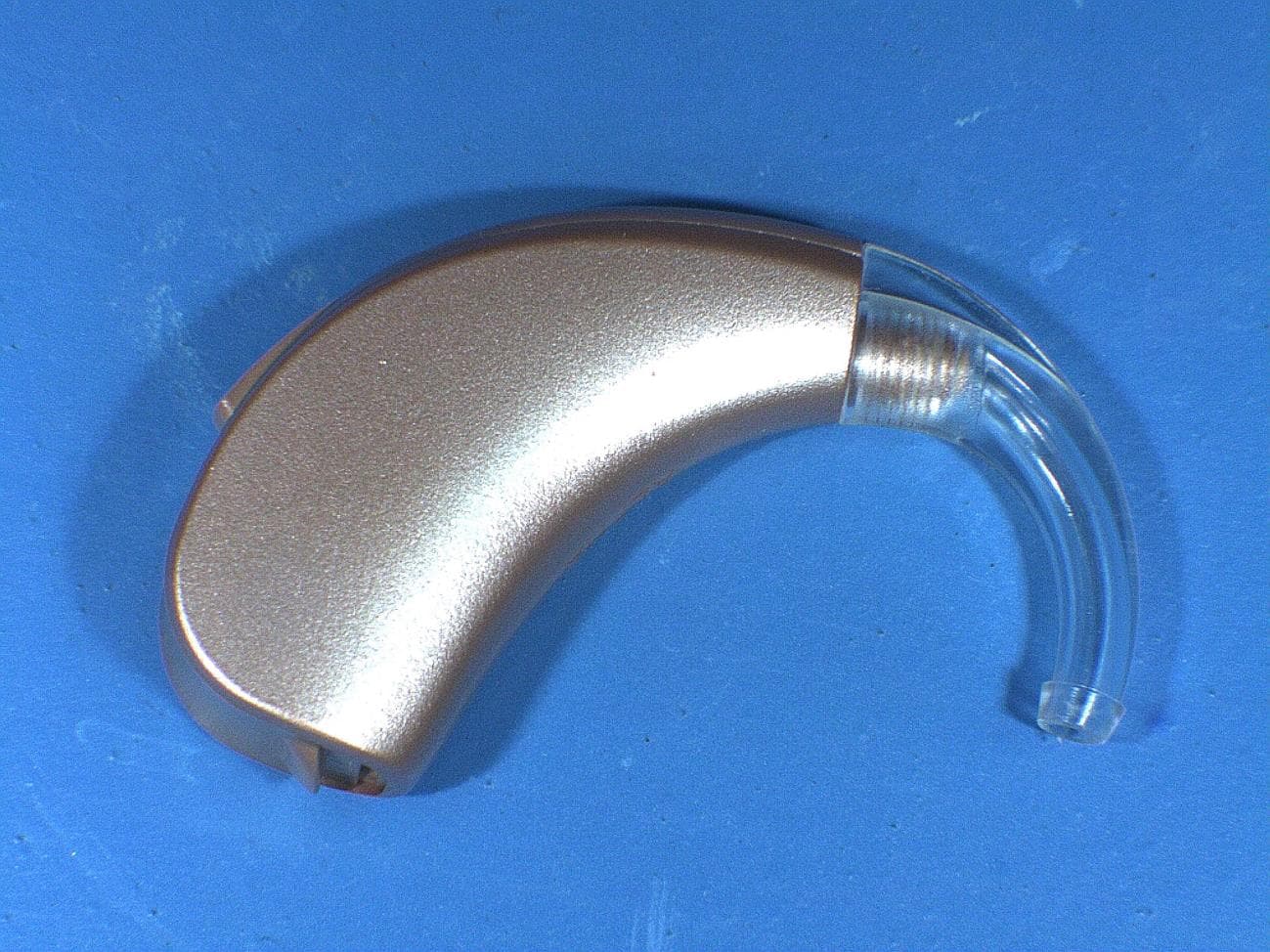
Click to zoom
Application Details
- Equipment Class
- DTS - Digital Transmission System
- Date of Grant
- Oct 27, 2014
- Application Purpose
- Original Equipment
- Date of Application
- Oct 27, 2014
- Equipment Note
- Halo B13
- Frequency Range
- 2402.00000000 - 2480.00000000
- Company
- Starkey Laboratories Inc
- Country
- United States
Documents & Files
Document Text
Text extracted from the exhibit documents filed with the FCC. Open a document above to read the original.
Users Manual
Made for iPhone ® RIC and BTE (Receiver-In-Canal) (Behind-The-Ear) OPERATIONS MANUAL 3 Table of Contents Overview RIC 13 Overview 4 BTE 13 Overview 5 Preparation Batteries 6 Battery Indicators 6 RIC 13 Insertion and Removal 10 BTE 13 Insertion and Removal 11 Operation On & Off 14 Adjusting Your Hearing System 14 Telephone Use 16 Hearing System Care Instrument Care 17 Hear Clear 17 Standard Tubing 18 Thin Tubing 18 Service and Repair 20 Troubleshooting Guide 21 Tips for Better Communication For You 22 For Your Family and Friends 23 Safety Information 24 FDA Information 26 FCC Information 29 Made for iPhone RIC and BTE, and TruLink are compatible with iPhone 5s, iPhone 5c, iPhone 5, iPhone 4s, iPad Air, iPad (4th generation), iPad mini with Retina display, iPad mini, and iPod touch (5th generation). 45 Made for iPhone RIC 13 Overview Made for iPhone BTE 13 Overview Features, Controls and Identification Your RIC hearing system controls include: Features, Controls and Identification Your BTE hearing system controls include: 1. Hearing Instrument 2. Cable 3. Receiver 4. Microphones 5. Battery Compartment (on/off control), Location of serial number 6. Retention Lock 7. Location of manufacturer’s name and model name 8. Location of left/right side receiver indicator 9. Instant Fit Earbud 10. Location of left/right side device indicator 11. Custom Earmold (optional) 12. RIC Custom Power Earmold (optional) 1. Hearing Instrument 2. Earhook 3. Microphones 4. Push Button (memory control) 5. Battery Compartment (on/off control) 6. Location of left/right side indicator, Location of serial number 7. Location of manufacturer’s name and model name 8. Standard Earmold with tubing 9. Universal thin tube with Instant Fit Earbud 10. Universal thin tube with Custom Eartip 1112 4 2 1 3 6 9 5 7 8 10 10 98 1 4 2 3 6 5 7 Serial Number 00-000000 67 PreparationPreparation Batteries Your hearing system uses a battery as its power source. This battery size can be identified by the orange (13) color code on the packaging. To insert or replace the battery: 1. Use the nail grip on the battery door. 2. Open the battery door gently and remove the old battery. 3. Remove the tab from the new battery. 4. Line up the battery’s “+” sign (flat side of the battery) with the “+” on the battery door. 5. Close the battery door. Battery Indicators An indicator will sound when the battery voltage is low. You have approximately 30 minutes* to replace the battery. An indicator may also sound just before the battery stops working. * Actual time between low battery indicator and shut down will vary depending on environmental noise levels and battery brand. 3 12 4 5 RIC 13 89 PreparationPreparation 3 12 4 5 Helpful Hints • NEVER FORCE THE BATTERY DOOR SHUT; this could result in serious damage; if the door will not close securely, check that the battery is inserted correctly. • Do not open the battery door too far or damage is likely to occur. • Dispose of used batteries immediately in the proper waste or recycling container. • Batteries vary in size and performance. Your hearing care professional is your best source for lifespan estimates and verification that you are using the proper size and type. BTE 13 Warnings Batteries are dangerous if swallowed. To help prevent the accidental ingestion of batteries: Keep out of reach of children and pets Check your medications before taking them – batteries have been mistaken for pills Never put batteries in your mouth, as they can easily be swallowed National Button Battery Ingestion Hotline: 202-625-3333 1011 PreparationPreparation RIC 13 Insertion and Removal To insert the earbud or earmold: 1. Hold the cable at the bend in front of the receiver with your thumb and forefinger. Gently insert the receiver into your ear canal (Fig. 1). 2. Wrap the hearing instrument over the top of your ear, carefully placing it behind your ear (Fig. 2). 3. Place the retention lock inside the bowl of your ear (Fig. 3). To remove the earbud or earmold: 1. Remove the retention lock from the bowl of your ear. 2. Remove the hearing instrument from behind your ear. 3. Grasp the receiver with your thumb and forefinger. Gently pull out of your ear canal. Do not pull with the hearing instrument case as this may damage the connection. BTE 13 Insertion and Removal To insert the Custom Earmold: 1. Hold the Custom Earmold with your thumb and forefinger on the outer side near the tubing (Fig. 1). 2. Tilt your hand slightly forward and gently insert the canal tip of the Custom Earmold into your ear canal (Fig. 2). 3. Rotate the Custom Earmold backward (Fig. 2). 4. Softly press the Custom Earmold into place with your fingertip (Fig. 3). 5. Carefully place the BTE behind your ear wrapping the earhook over the top of your ear. To remove the Custom Earmold: Take the instrument from behind your ear and gently pull the Custom Earmold outward. Pulling lightly down on the earlobe may help loosen the Custom Earmold as it is removed. Figure 1Figure 1 Figure 2Figure 2 Figure 3Figure 3 1213 PreparationPreparation Instant Fit Earbud or Custom Eartip for BTE 13 To insert the Instant Fit Earbud or Custom Eartip: 1. Insert the Instant Fit Earbud/ Custom Eartip into your ear canal (Fig. 1). 2. Gently wrap the BTE over your ear until it rests securely behind your ear (Fig. 2). 3. Place the lock in the concha bowl of your ear (Fig. 3). To remove the Instant Fit Earbud or Custom Eartip: 1. Remove the lock from the concha bowl of your ear. 2. Remove the hearing instrument from behind your ear. 3. Gently grasp the tubing at the opening of the ear canal and pull outward. Figure 1 Figure 2 Figure 3 Helpful Hints • Minor irritation and inflammation may occur as your ear becomes accustomed to having an object in it; if so, please contact your hearing care professional. • If an actual allergic reaction occurs, alternative earmold materials are available; contact your hearing care professional. • Severe swelling, discharge from the ear, excessive wax or oth…
Text truncated - open the document above for the full version.
Cover Letter(s)
WTD 13.4.9 FCC Compliance Opinion STAK0041 Information about the Applicant Grantee (Company Name) Starkey Laboratories, Inc. FCC Contact Person Ken Meyer Address 6600 Washington Ave S. City, State, Zip Eden Prairie, MN 55344 Job Number STAK0041 Model Halo B13 FCC ID EOA-24HALOBTE13 Agent William Mitchell Approval Type Original Equipment Class DTS Digital Transmission System Rule Part 15.247 Overview This application is for a wireless hearing aid. Wireless features are used during fitting and to communicated control information and digital audio to and from Bluetooth LE devices. Confidentiality requested for allowed files. Request is properly addressed and referenced. Short term confidentiality requested. Recommendation All items have been resolved and completed to my satisfaction; therefore I recommend this application for approval. Signature Dave Tolman, TCB Committee 10/25/2014
External Photos
Left side Right side Top Bottom Ear hook end Battery end
ID Label/Location Info
FCC Home | Search | RSS | Updates | E-Filing | Initiatives | Consumers | Find People Office of Engineering and Technology Subject: Response to Inquiry to FCC (Tracking Number 910389) (TCB) From: <[email protected]> Date: 11/25/2013 9:17 AM To: <[email protected]> Link to Federal Communications Commission Home Office of Engineering and Technology Inquiry on 11/19/2013 : Inquiry: The applicant Starkey Laboratories Inc is requesting that they be allowed to place the FCC ID label for their device in the User Manual rather than on the device itself, which is a wireless hearing aid. Due to the extremely small size of the device, they believe the ID label would become illegible if they had to reduce the font size small enough to fit on the device Starkey submitted a similar request a few years ago for FCC ID: EOA-IRIS-HA and the FCC gave them permission to place the label in the manual. They are asking for that same permission for this current application. Attached are photos showing the size of the previous device and label and photos showing the size of the current device and label. Please let us know if you need additional information. Thanks. FCC response on 11/25/2013 FCC Rule SecƟon §2.925 (f) specifically allows for the FCCID to be placed other than on the device. Reason stated below: Where it is shown that a permanently affixed nameplate is not desirable or is not feasible, an alternaƟve method of posiƟ vely idenƟfying the equipment may be used if approved by the Commission. The proposed alternaƟve method of idenƟficaƟon and the jusƟficaƟon for its use must be included with the applicaƟon for equipment authorizaƟon. Similarly, KDB 784748 D01 provides guidance that allows the FCCID to be placed in the user’s manual. The FCC approves your request to place the FCC ID in the user’s manual. Accordingly, you are allowed to place the FCCID in the user’s manual. Please note that the approval of this condiƟon by the FCC must be must be included in the applicaƟon for cerƟficaƟon. Response to Inquiry to FCC (Tracking Number 910389) (TCB) 1 of 211/25/2013 9:42 AM Attachment Details: Photos showing sample devices Do not reply to this message. Please select the Reply to an Inquiry Response link from the OET Inquiry System to add any additional information pertaining to this inquiry. Response to Inquiry to FCC (Tracking Number 910389) (TCB) 2 of 211/25/2013 9:42 AM 30325-100-01.xlsxPage 1 The information contained in this document is Confidential, Proprietary and Trade Secret of Starkey. Do not copy or disclose any Information in this document without written permission from an officer of Starkey. Copyright © 2014 Starkey REV ENGRDOCRLSD DATE 01 KKEG8/19/2014 LineFont#ID 2Arial 591 3Arial 591 NOTES: 1. All dimensions are for Reference Only 2. Dimensions Depic Maximum Character window 3. All Tex to be centered in window 4. Use import CE file for CE, Arial font for 0086 5. Use import file for text box 1 6. Ink colors limited to the Starkey Standard colors By Date 7. Fixture: 22389-000, 22385-000, 21937-000 Laser Fixture DRFT 8/5/2014 CHKD 8/6/2014 \ MKTG 8/15/2014 Size:Scale:Rev QLTY 8/15/2014 C1/1 1 Import File/ See Note 5 659738XX1 MICROTECH Import File/ See Note 5 65973CXX1 AUDIGY Import File/ See Note 5 65973 Molly Loe Part No: Jodi Rickheim 30325-100 Tolerance unless otherwise specified Inches (MM) Signature Title: Cynthia/Carmen Jackson 2.4 GHz BTE 13 Label Control Drawing Gary Zajicek 7XX1 PER CUSTOMER REQUEST 659734XX1 NUEAR LOGO ID# Import File/ See Note 5 659731XX1 Eng Release STARKEY Import File/ See Note 5 659732XX1 AUDIBEL Import File/ See Note 5 BASETAB TEXT BOX LASER PRINTED TEXT FONT Laser Text XX-XX XXXX REVISIONS (ALL SHEETS ARE SAME REV) PRO/ECOCHANGE DESCRIPTION MN43308 6700 Washington Ave. South Eden Prairie, MN, 55344 Tel. 952-941-6401 Fax 952-828-9262 TEXT BOX 1 .631 .150
Internal Photos
Circuit board top side Circuit board bottom side
Internal Photos
Left side Right side Top Bottom Ear hook end Battery end
Operational Description
Antenna Description The antenna is an asymmetric dipole. The antenna is constructed on a polyimide flexible circuit. The flexible circuit uses 1 ounce copper (1.4 mil). The left dipole element shown in Figure 1 is approximately 0.76 inches long. The right dipole element is approximately 0.57 inches to the junction with the vertical section of copper. The length of the vertical section is approximately 0.42 inches. The peak gain of the antenna in the assembled DUT is –7 dBi. Figure 1 Antenna artwork.
RF Exposure Info
RF Exposure Evaluation FCC ID: EOA-24HALOBTE13 The device is excluded from SAR evaluation and therefore deemed compliant with FCC RF exposure requirements as described below: FCC KDB 447498 D01 v05r02 Section 4.3.1 “The 1-g and 10-g SAR test exclusion thresholds for 100 MHz to 6 GHz at test separation distances ≤ 50 mm are determined by: [(max. power of channel, including tune-up tolerance, mW)/(min. test separation distance, mm)] · [√f(GHz)] ≤ 3.0 for 1-g SAR and ≤ 7.5 for 10-g extremity SAR, where f(GHz) is the RF channel transmit frequency in GHz Power and distance are rounded to the nearest mW and mm before calculation The result is rounded to one decimal place for comparison 3.0 and 7.5 are referred to as the numeric thresholds in the step 2 below The test exclusions are applicable only when the minimum test separation distance is ≤ 50 mm and for transmission frequencies between 100 MHz and 6 GHz. When the minimum test separation distance is < 5 mm, a distance of 5 mm according to 5) in section 4.1 is applied to determine SAR test exclusion.” The device has a maximum conducted output power of 0.722 mW (-1.41 dBm) at 2480.0 MHz. The antenna is a flexible circuit asymmetrical dipole with a peak gain of -7.0 dBi. The resulting effective radiated power is 0.144212 mW EIRP. The closest spacing of the antenna to the user’s torso is < 5 cm. The table below shows the results of the calculation. The value of 0.045 is well below the exclusion threshold of 3.0, therefore the unit is excluded from SAR evaluation and deemed compliant with FCC RF exposure requirements. EIRP Test Separation Transmit Frequency Exclusion Threshold Specification (mW) (mm) (GHz) 0.144212 5 2.480 0.045 <=3.0
Test Report
This report must not be used to claim product certification, approval, or endorsement by NVLAP, NIST, or any agency of the federal government of the United States of America. This Report may only be duplicated in its entirety Starkey Laboratories, Inc. BTE 13 Hearing Aid Models: Halo B13; A3i B13; Start 10i B13; Start 9i B13 FCC 15.247:2014 Report # STAK0041 NVLAP Lab Code: 200881-0 WTD 13.9.30 CERTIFICATE OF TEST Product compliance is the responsibility of the client; therefore, the tests and equipment modes of operation represented in this report were agreed upon by the client, prior to testing. The results of this test pertain only to the sample(s) tested. The specific description is noted in each of the individual sections of the test report supporting this certificate of test. Last Date of Test: October 14, 2014 Starkey Laboratories, Inc. BTE 13 Hearing Aid Models: Halo B13; A3i B13; Start 10i B13; Start 9i B13 Radio Equipment Testing Standards Specification Method FCC 15.247:2014 ANSI C63.10:2009 Results Method Clause Test Description Applied Results Comments 6.2 AC Powerline Conducted Emissions No N/A Not required for a battery powered EUT. 6.5, 6.6 Spurious Radiated Emissions Yes Pass 6.7 Band Edge Compliance No Pass 6.7 Spurious Conducted Emissions No Pass 6.9.1 Occupied Bandwidth Yes Pass 6.10.2 Output Power Yes Pass 6.11.2 Power Spectral Density Yes Pass 7.5 Duty Cycle Yes Pass Deviations From Test Standards None Approved By: Tim O'Shea, Operations Manager REV 2012.08.02 REVISION HISTORY Revision Number Description Date Page Number 00 None Barometric Pressure The recorded barometric pressure has been normalized to sea level. REV 2014.08.11 ACCREDITATIONS AND AUTHORIZATIONS United States FCC - Designated by the FCC as a Telecommunications Certification Body (TCB). Certification chambers, Open Area Test Sites, and conducted measurement facilities are listed with the FCC. A2LA - Accredited by A2LA to ISO / IEC Guide 65 as a product certifier. This allows Northwest EMC to certify transmitters to FCC and IC specifications. NVLAP - Each laboratory is accredited by NVLAP to ISO 17025 Canada IC - Recognized by Industry Canada as a Certification Body (CB). Certification chambers and Open Area Test Sites are filed with IC. European Union European Commission – Validated by the European Commission as a Conformity Assessment Body (CAB) under the EMC directive and as a Notified Body under the R&TTE Directive. Australia/New Zealand ACMA - Recognized by ACMA as a CAB for the acceptance of test data. Korea MSIP / RRA - Recognized by KCC’s RRA as a CAB for the acceptance of test data. Japan VCCI - Associate Member of the VCCI. Conducted and radiated measurement facilities are registered. Taiwan BSMI – Recognized by BSMI as a CAB for the acceptance of test data. NCC - Recognized by NCC as a CAB for the acceptance of test data. Singapore IDA – Recognized by IDA as a CAB for the acceptance of test data. Israel MOC – Recognized by MOC as a CAB for the acceptance of test data. Hong Kong OFTA – Recognized by OFTA as a CAB for the acceptance of test data. Vietnam MIC – Recognized by MIC as a CAB for the acceptance of test data. SCOPE For details on the Scopes of our Accreditations, please visit: http://www.nwemc.com/accreditations/ REV 2012.08.02 MEASUREMENT UNCERTAINTY Measurement Uncertainty When a measurement is made, the result will be different from the true or theoretically correct value. The difference is the result of tolerances in the measurement system that cannot be completely eliminated. To the extent that technology allows us, it has been our aim to minimize this error. Measurement uncertainty is a statistical expression of measurement error qualified by a probability distribution. A measurement uncertainty estimation has been performed for each test per our internal quality document WP 342. The estimation is used to compare the measured result with its "true" or theoretically correct value. The expanded measurement uncertainty (K=2) for each test is on each data sheet. Our measurement data meets or exceeds the measurement uncertainty requirements of the applicable specification; therefore, the test data can be compared directly to the specification limit to determine compliance. The calculations for estimating measurement uncertainty are based upon ETSI TR 100 028 (or CISPR 16-4-1 as applicable), and are available upon request. The following table represents the Measurement Uncertainty (MU) budgets for each of the tests that may be contained in this report. Test + MU - MU Frequency Accuracy (Hz) 0.12 -0.01 Amplitude Accuracy (dB) 0.49 -0.49 Conducted Power (dB) 0.41 -0.41 Radiated Power via Substitution (dB) 0.69 -0.68 Temperature (degrees C) 0.81 -0.81 Humidity (% RH) 2.89 -2.89 Field Strength (dB) 4.00 -4.00 AC Powerline Conducted Emissions (dB) 2.70 -2.70 REV 2013.06.28 FACILITIES Oregon Labs EV01-12 22975 NW Evergreen Pkwy Hillsboro, OR 97124 (503) 844-4066 California Labs OC01-13 41 Tesla Irvine, CA 92618 (949) 861-8918 New York Labs NY01-04 4939 Jordan Rd. Elbridge, NY 13060 (315) 685-0796 Minnesota Labs MN01-08 9349 W Broadway Ave. Brooklyn Park, MN 55445 (763) 425-2281 Washington Labs NC01-05,SU02,SU07 19201 120 th Ave. NE Bothell, WA 98011 (425) 984-6600 VCCI A-0108 A-0029 A-0109 A-0110 Industry Canada 2834D-1, 2834D-2 2834B-1, 2834B-2, 2834B-3 2834E-1 2834F-1 NVLAP NVLAP Lab Code: 200630-0 NVLAP Lab Code: 200676-0 NVLAP Lab Code: 200761-0 NVLAP Lab Code: 200881-0 NVLAP Lab Code: 200629-0 WTD 13.9.30 PRODUCT DESCRIPTION Client and Equipment Under Test (EUT) Information Company Name: Starkey Laboratories, Inc. Address: 6600 Washington Ave S. City, State, Zip: Eden Prairie, MN 55344 Test Requested By: Bill Mitchell Model: Halo B13; A3i B13; Start 10i B13; Start 9i B13 First Date of Test: September 25, 2014 Last Date of Test: October 14, 2014 Receipt Date of Samples: September 25, 2014 Equipment Design Stage: Production Equipment Condition: No Damage Information Provided by the Par…
Text truncated - open the document above for the full version.
Test Setup Photos
photo SE 001.jpg SE 002.jpg SPURIOUS RADIATED EMISSIONS PSA-ESCI 2014.06.19 photo SE 003.jpg SPURIOUS RADIATED EMISSIONS PSA-ESCI 2014.06.19 BAND EDGE COMPLIANCE XMit 2014.02.07 NORTHWEST BAND EDGE COMPLI NweTx 2014.09.23 EMC DIRECT 001.jpg BAND EDGE COMPLIANCE SPURIOUS CONDUCTED EMISSIONS XMit 2014.02.07 NORTHWEST SPURIOUS CONDUCT NweTx 2014.09.23 EMC DIRECT 001.jpg SPURIOUS CONDUCTED EMISSIONS OCCUPIED BANDW IDTH XMit 2014.02.07 NORTHWEST OCCUPIED BANDWID NweTx 2014.09.23 EMC DIRECT 001.jpg OCCUPIED BANDWIDTH OUTPUT POWER XMit 2014.02.07 NORTHWEST OUTPUT POWER NweTx 2014.09.23 EMC DIRECT 001.jpg OUTPUT POWER POWER SPECTRAL DENSITY XMit 2014.02.07 NORTHWEST POWER SPECTRAL D NweTx 2014.09.23 EMC DIRECT 001.jpg POWER SPECTRAL DENSITY DUTY CYCLE XMit 2014.02.07 NORTHWEST DUTY CYCLE NweTx 2014.09.23 EMC DIRECT 001.jpg DUTY CYCLE
Contact Information
Applicant
William John Mitchell(Principal Regulatory Affairs Engineer)
Test Firm
Northwest EMC, Inc.Greg Kiemel
Technical Specifications
| # | Rule Parts | Frequency Range | Power Output |
|---|---|---|---|
| 1 | 15C | 2.40 GHz - 2.48 GHz | 722.00 µW |
Other Applications from Starkey Laboratories Inc
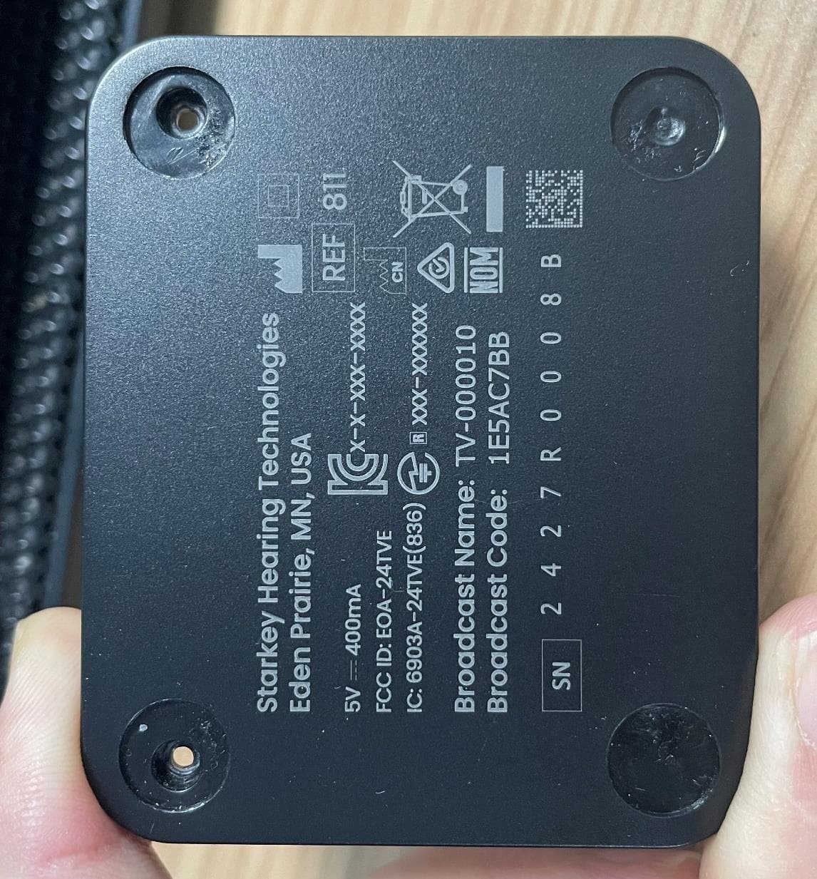
EOA-24TVE
Aug 18, 2024Starlink Edge TV
Equipment Class
DTS - Digital Transmission System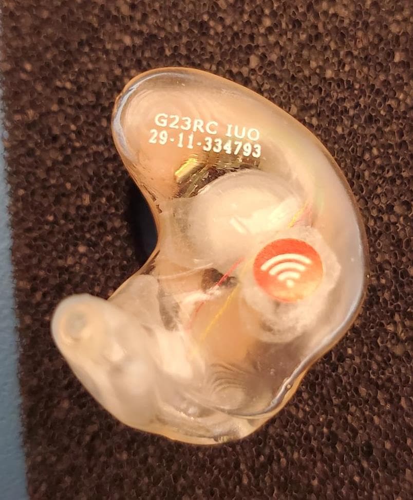
EOA-24EDGITERCH
Jul 17, 2024Edge AI ITE right
Equipment Class
DTS - Digital Transmission System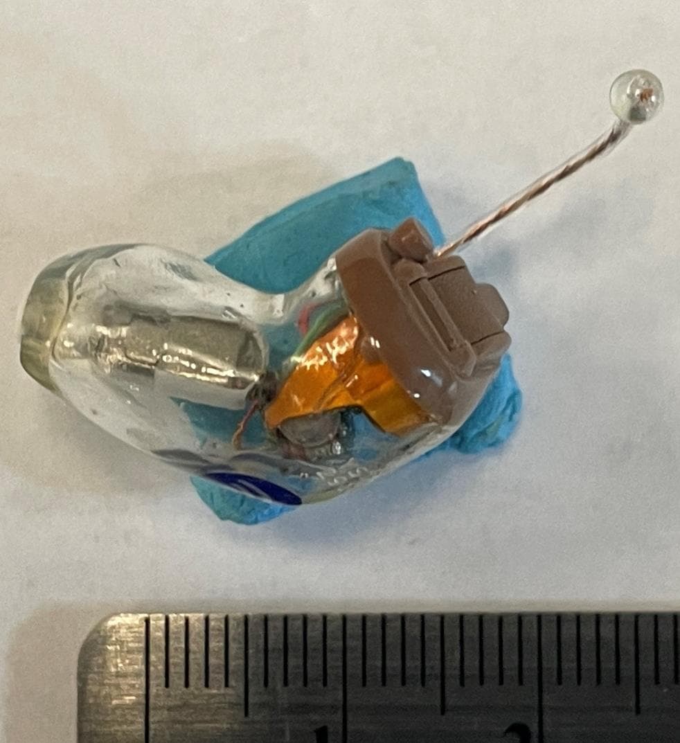
EOA-24EDGCIC
Jul 17, 2024Edge AI CIC
Equipment Class
DTS - Digital Transmission System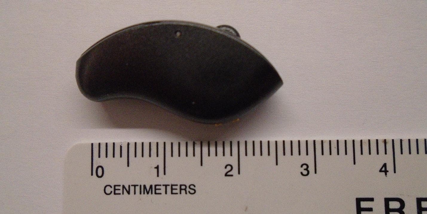
EOA-24EDGMRIC
Jul 17, 2024Edge AI mRIC R
Equipment Class
DTS - Digital Transmission System
EOA-24EDGITELCH
Jul 17, 2024Edge AI ITE left
Equipment Class
DTS - Digital Transmission System