EOA-IRIS-HAWi Series RIC
Starkey Laboratories Inc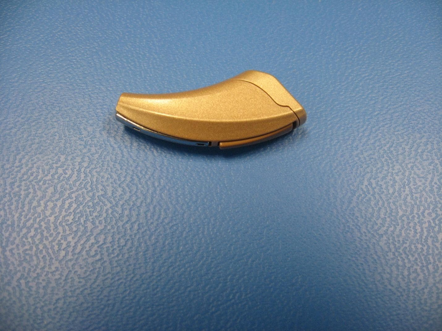
Click to zoom
Application Details
- Equipment Class
- DXX - Part 15 Low Power Communication Device Transmitter
- Date of Grant
- Aug 23, 2010
- Application Purpose
- Original Equipment
- Date of Application
- Aug 23, 2010
- Equipment Note
- Wi Series RIC
- Frequency Range
- 906.00000000 - 922.06000000
- Company
- Starkey Laboratories Inc
- Country
- United States
Documents & Files
Document Text
Text extracted from the exhibit documents filed with the FCC. Open a document above to read the original.
Users Manual
RIC (Receiver-In-Canal) OPERATIONS MANUAL Table of Contents Overview Features, Controls and Identification .................................2 Preparation Batteries .............................................................................4 Battery Indicators ...............................................................6 Insertion and Removal Instant Fit Earbud and Custom Eartip ................................8 Operation On & Off ...........................................................................10 Multimemory Settings ......................................................11 Directional Settings ..........................................................12 Telephone Use ..................................................................12 Accessories Wireless Accessories ........................................................14 Hearing System Care Instrument Care ................................................................15 Service and Repair ............................................................17 Tips for Better Communication For You .............................................................................18 For Your Family and Friends .............................................19 Saftey Information ...................................................................20 FDA Information. .....................................................................22 FCC Information ......................................................................24 Limited Warranty......................................................................25 1 2 Overview Features, Controls and Identification Your hearing system controls include: 1. Hearing Instrument 2. Cable 3. Receiver 4. Microphone(s) 5. Multifunction Button 6. Battery Compartment (on/off control) Location of serial number 7. Retention Lock 8. Location of manufacturer’s name and model name 9. Location of left/right side indicator 10. Instant Fit Earbud 11. Custom Earmold (optional) 12. RIC Custom Power Earmold (optional) Your hearing system has wireless capabilities that allow for communication between your two hearing instruments. This feature may have been customized for you by your hearing care professional. Please consult your hearing care professional regarding your customized settings and patient report. 3 2 Overview 3 1211 10 4 9 8 5 6 1 7 4 Preparation Batteries Your hearing system uses a battery as its power source. This battery size can be identified by the brown (312) color code on the battery packaging. To insert or replace the battery: 1. Use the nail grip on the battery door. 2. Remove the tab from the new battery. 3. Open the battery door gently and remove the old battery. 4. Line up the battery’s plus “+” sign (flat side of the battery) with the “+” on the battery door. 5. Close the battery door. 5 Preparation 12 3 4 5 6 Preparation Battery Indicators An indicator will sound when the battery’s voltage is low. You have approximately 5 minutes* to replace the battery. An indicator will also sound just before the battery stops working. * Actual time between low battery indicator and shut down will vary depending on environmental noise levels and brand of battery used. Helpful Hints • NEVER FORCE THE BATTERY DOOR SHUT; this could result in serious damage; if the door will not close securely, check that the battery is inserted correctly • Do not open the battery door too far or damage is likely to occur • Dispose of used batteries immediately in the proper waste or recycling container 7 Preparation • Because batteries can vary in size and performance, your hearing care professional is your best source for lifespan estimates and verification that you are using the proper size and type Warnings Batteries are dangerous if swallowed. To help prevent the accidental ingestion of batteries: Keep out of reach of children and pets Check your medications before taking them – batteries have been mistaken for pills Never put batteries in your mouth, as they can easily be swallowed National Button Battery Ingestion Hotline: 202-625-3333 8 Insertion and Removal Insertion and Removal To insert the Instant Fit Earbud or Custom Eartip: 1. Hold the cable at the bend in front of the receiver with your thumb and forefinger. Gently insert the receiver into your ear canal. 2. Carefully place the hearing instrument behind your ear, wrapping it over the top of your ear. 3. Place the lock inside the bowl of your ear. To remove the Instant Fit Earbud or Custom Eartip: 1. Remove the lock from the bowl of your ear. 2. Remove the hearing instrument from behind your ear. 3. Grasp the receiver with your thumb and forefinger. Gently pull out of your ear canal. Do not pull with the hearing instrument case as this may damage the connection. 9 Insertion and Removal Helpful Hints • Minor irritation and inflammation may occur as your ear becomes accustomed to having an object in it; if so, please contact your hearing care professional. • If an actual allergic reaction occurs, alternative earmold materials are available; contact your hearing care professional. • Severe swelling, discharge from the ear, excessive wax, or other unusual conditions warrant immediate consultation with a physician. 10 Operation On & Off To turn ON: Insert a battery and completely close the battery door. To turn OFF: Open the battery door until the battery is no longer touching the battery contacts. Your hearing instrument has a Power-On delay. The Power-On delay means that your hearing instruments will take several seconds to power up once they have been turned on. This feature allows you to get the hearing instruments in your ear before they start to amplify sound. You may hear a tone series indicating that your device is fully powered on. 11 Multimemory Button Your hearing care professional can set up to four hearing programs for you. These additional programs are accessed by pressing the Multimemory button inward. Consult your hearing care professional for your …
Text truncated - open the document above for the full version.
External Photos
IRIS hearing aid including memory switch Memory Switch
ID Label/Location Info
SHARC bottom view showing label location Label location Eden Prairie, MN, USA SurfLink Programmer Paradigm 0673 N 13634 FCC ID: EOA-WP IC: 6903A-WP 5 vDC 200 mA
Internal Photos
IRIS hearing aid internal construction showing bottomside flex circuit and mounting frame. Antenna not shown IRIS hearing aid internal construction showing topside flex circuit and mounting frame. Antenna not shown IRIS Hearing Aid with case cover removed and foil antenna bend up to reveal circuitry
Test Report
TEST REPORT Report Number: 100105325MIN-002A Project Number: G100105325 Testing performed on the Opal RIC 312 FCC ID: EOA-IRIS-HA Industry Canada ID: 6903A-IRISHA to 47 CFR Part 15. 249:2009 RSS- 210, Issue 7, 2007 For Starkey Laboratories, Inc. Test Performed by: Test Authorized by: Intertek Testing Services NA, Inc. 7250 Hudson Blvd., Suite 100 Oakdale, MN 55128 Starkey Laboratories, Inc. 6700 Washington Avenue South Eden Prairie, MN 55344 Prepared by: Date: July 8, 2010 Richard Blonigen Reviewed by: Date: July 8, 2010 Uri Spector This report is for the exclusive use of Intertek's Client and is provided pursuant to the agreement between Intertek and its Client. Intertek's responsibility and liability are limited to the terms and conditions of the agreement. Intertek assumes no liability to any party, other than to the Client in accordance with the agreement, for any loss, expense or damage occasioned by the use of this report. Only the Client is authorized to copy or distribute this report and then only in its entirety. Any use of the Intertek name or one of its marks for the sale or advertisement of the tested material, product or service must first be approved in writing by Intertek. The observations and test results in this report are relevant only to the sample tested. This report by itself does not imply that the material, product, or service is or has ever been under an Intertek certification program. This report must not be used to claim product endorsement by A2LA, NIST nor any other agency of the U.S. Government. EMC Report No: 100105325MIN-002A FCC ID: EOA-IRIS-HA IC ID: 6903A-IRISHAPage 2 of 28 TABLE OF CONTENTS 1.0 GENERAL DESCRIPTION................................ ................................................................ ................................................................ ................................................................ .............................................. ............................ .............. 3 33 3 1.1 Product Description; Test Facility ....................................................................................... 4 1.3 Environmental conditions.................................................................................................... 5 1.4 Measurement uncertainty ................................................................................................... 6 1.5 Field Strength Calculation................................................................................................... 6 2.0 TEST SUMMARY................................ ................................................................ ................................................................ ................................................................ .......................................................... .................................................... .......................... 7 77 7 3.0 TEST CONDITIONS AND RESULTS................................ ................................................................ ................................................................ ................................................................ ................................. .. . 8 88 8 3.1 Field strength of fundamental ............................................................................................. 8 3.2 Field strength of harmonics and spurious emissions ....................................................... 10 3.3 Bandwidth of Emissions.................................................................................................... 16 3.4 Transmitter power line conducted emissions ................................................................... 23 3.5 Receiver/digital device radiated emissions....................................................................... 24 3.6 Digital device conducted emissions.................................................................................. 28 4.0 TEST EQUIPMENT................................ ................................................................ ................................................................ ................................................................ ....................................................... .............................................. .......................29 2929 29 EMC Report No: 100105325MIN-002A FCC ID: EOA-IRIS-HA IC ID: 6903A-IRISHAPage 3 of 28 1.0 GENERAL DESCRIPTION Model: Opal RIC 312 Type of EUT: Hearing Aid Serial Number: N/A FCC ID: EOA-IRIS-HA Industry Canada ID: 6903A-IRISHA Related Submittal(s) Grants: None Company: Starkey Laboratories Inc. Customer: Mr. Ken Meyer Address: 6700 Washington Avenue South Eden Prairie, MN 55344 Phone: (952) 947-4734 Fax: (952) 828-9262 Email: [email protected] Test Standards: 47 CFR, Part 15:2009, §15.249 RSS–210, Issue 7, 2007 RSS-Gen, Issue 2, 2007 47 CFR, Part 15:2008, §15.107 and §15.109, Class B Other Type of radio: Stand -alone Module Hybrid Date Sample Submitted: July 7, 2010 Test Work Started: July 7, 2010 Test Work Completed: July 7, 2010 Test Sample Conditions: Damaged Poor (Usable) Good EMC Report No: 100105325MIN-002A FCC ID: EOA-IRIS-HA IC ID: 6903A-IRISHAPage 4 of 28 1.1 Product Description; Test Facility Product Description: Hearing Aid Operating Frequency 902-928 MHz Number of Channels 11 Channels Modulation: FSK Emission Designator: 323KFXD Antenna(s) Info: Integral Antenna Installation: User Professional Factory Transmitter Power Configuration: Internal battery External power source 120VAC 230VAC 400VAC VDC Other: Amp. 50Hz 60Hz Test Facility Accreditation: A2LA (Certificate No. 1427.01) Test Methodology: Measurements performed according to the procedures in ANSI C63.4- 2003 EMC Report No: 100105325MIN-002A FCC ID: EOA-IRIS-HA IC ID: 6903A-IRISHAPage 5 of 28 1.2 EUT Configuration The equipment under test was operated during the measurement under the following conditions: - Standby - Continuous transmission in modulated mode - Con…
Text truncated - open the document above for the full version.
Test Setup Photos
Test Setup Photos
Contact Information
Applicant
William John Mitchell(Principal Regulatory Affairs Engineer)
Technical Contact
Starkey LaboratoriesKenneth J Meyer
[email protected]9529474734
6600 Washington Ave S. · Eden Prairie · United States
Test Firm
Intertek Testing ServicesUri Spector
Technical Specifications
| # | Rule Parts | Frequency Range | Power Output |
|---|---|---|---|
| 1 | 15C | 906 MHz - 922.06 MHz | - |
Other Applications from Starkey Laboratories Inc
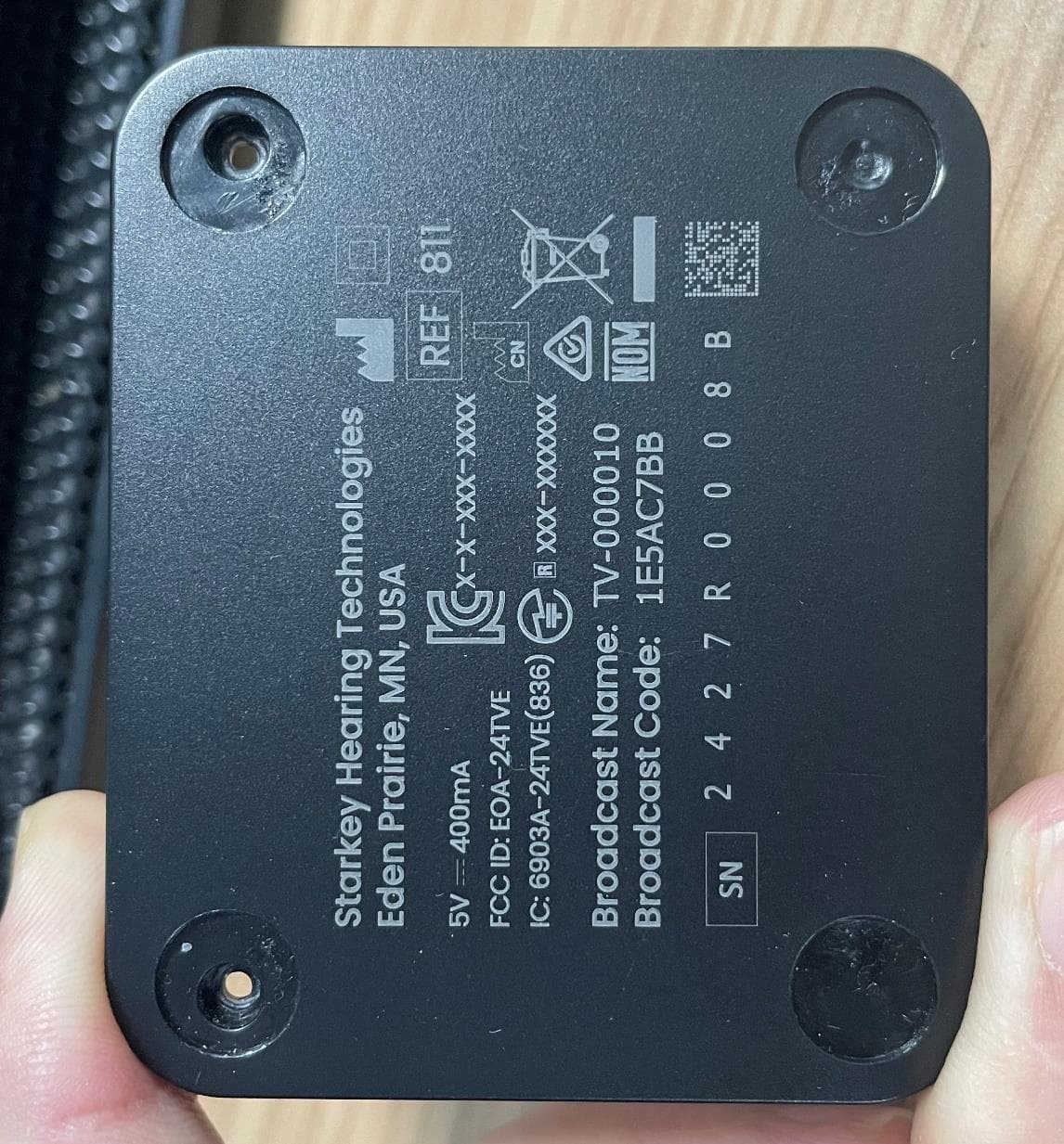
EOA-24TVE
Aug 18, 2024Starlink Edge TV
Equipment Class
DTS - Digital Transmission System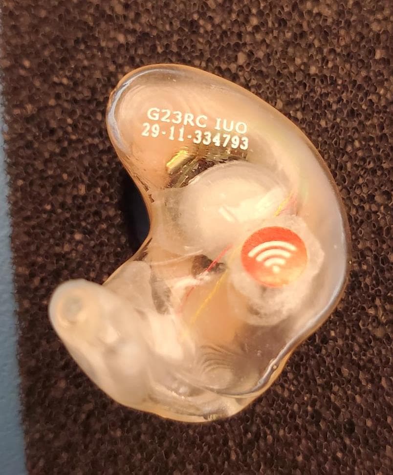
EOA-24EDGITERCH
Jul 17, 2024Edge AI ITE right
Equipment Class
DTS - Digital Transmission System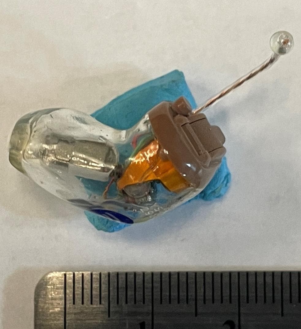
EOA-24EDGCIC
Jul 17, 2024Edge AI CIC
Equipment Class
DTS - Digital Transmission System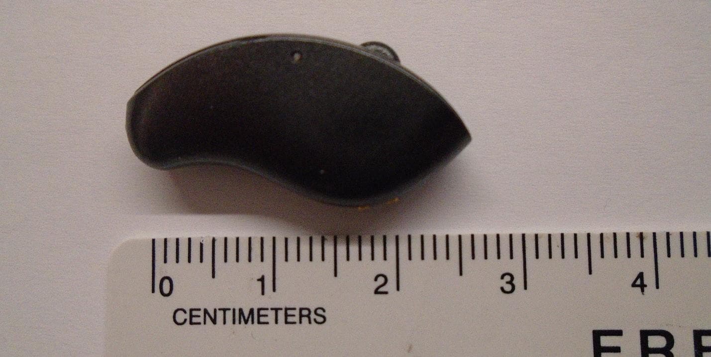
EOA-24EDGMRIC
Jul 17, 2024Edge AI mRIC R
Equipment Class
DTS - Digital Transmission System
EOA-24EDGITELCH
Jul 17, 2024Edge AI ITE left
Equipment Class
DTS - Digital Transmission System