EOA-TV200
Starkey Laboratories Inc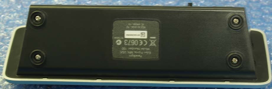
Click to zoom
Application Details
- Equipment Class
- DTS - Digital Transmission System
- Date of Grant
- Nov 29, 2010
- Application Purpose
- Original Equipment
- Date of Application
- Nov 29, 2010
- Equipment Note
- 200
- Frequency Range
- 904.60000000 - 926.10000000
- Company
- Starkey Laboratories Inc
- Country
- United States
Documents & Files
Document Text
Text extracted from the exhibit documents filed with the FCC. Open a document above to read the original.
Users Manual
MEDIA 23 SurfLink Media Controls Overview Power Streaming Activation Control Volume Control Microphone RCA Jacks Optical S/PDIF Monaural/Binaural Power TOSLINK Selection Back View Read This First SurfLink Media can be connected to most media sources, including televisions, radios, and MP3 players. This guide provides easy step-by-step instructions for connecting and using SurfLink Media. SurfLink Media must be powered on and connected to the desired media input before your hearing instruments can receive a signal. Only ONE of the following connection setups needs to be followed to begin the use of SurfLink Media. A variety of cables are included in this package to allow streaming from virtually any media source. Select the appropriate cable for your connection and store any unused cables. Package Contents • SurfLink Media • Power Adaptor • RCA Cable • Microphone Cable Microphone (1) A microphone cable is supplied. RCA Jacks (2) An RCA audio cable is supplied. Optical TOSLINK Jack (3) A TOSLINK cable is not supplied. TOSLINK cables are available at most consumer electronic stores. S/PDIF Jack (4) An S/PDIF digital audio cable is not supplied. S/PDIF digital audio cables are available at most consumer electronic stores. Power (5) A micro-USB power cable is supplied. Insert the micro-USB connector into the Power port on SurfLink Media and connect the opposite end to the power outlet. 45 Connecting SurfLink Media and Media Source RCA Cable Installation (most common connection option) 1. Connect the red and white RCA cable plugs into the corresponding red and white RCA jacks (labeled 2) on SurfLink Media. 2. Select the signal type as Monaural or Binaural audio stream based on your hearing system confi guration. Monaural if you are wearing one hearing instrument. Binaural if you are wearing two hearing instruments. 3. Connect the opposite end of the red and white RCA cable jacks into the corresponding red and white RCA “AUDIO OUT” jacks on the media source. 4. Place SurfLink Media in a desired location that is in close proximity to the media source. Once SurfLink Media has been turned on it will begin to stream the audio signal. Connecting SurfLink Media and Media Source S/PDIF Installation 1. Connect the orange S/PDIF cable into the orange S/PDIF “AUDIO OUT” port (labeled 4) on the media source. 2. Select the signal type as Monaural or Binaural audio stream based on your hearing system confi guration. Monaural if you are wearing one hearing instrument. Binaural if you are wearing two hearing instruments. 3. Connect the opposite end of the orange S/PDIF cable into the orange S/PDIF port on the back of SurfLink Media. 4. Place SurfLink Media in a desired location that is in close proximity to the media source. Once SurfLink Media has been turned on it will begin to stream the audio signal. Power Streaming Activation Control Volume Control Microphone RCA Jacks Optical S/PDIF Monaural/Binaural Power TOSLINK Selection Optical S/PDIF Monaural/Binaural Power SLINK Selection Power Streaming Activation Control Volume Control Microphone RCA Jacks Optical S/PDIF Monaural/Binaural Power TOSLINK Selection Optical S/PDIF Monaural/Binaural Power SLINK Selection 67 Connecting SurfLink Media and Media Source Optical/TOSLINK Installation 1. Connect the optical/TOSLINK cable into the optical/TOSLINK “AUDIO OUT” port (labeled 3) on the media source. 2. Select the signal type as Monaural or Binaural audio stream based on your hearing system confi guration. Monaural if you are wearing one hearing instrument. Binaural if you are wearing two hearing instruments. 3. Connect the opposite end of the optical/ TOSLINK cable into the optical/TOSLINK port on the back of SurfLink Media. 4. Place SurfLink Media in a desired location that is in close proximity to the media source. Once SurfLink Media has been turned on it will begin to stream the audio signal. Connecting SurfLink Media and Media Source External Microphone Installation In the instance your television does not support the cable installation options listed on the previous pages, an external microphone can be used. 1. Connect the microphone cable into the microphone port (labeled 1) on the back of SurfLink Media. 2. Select the signal type as Monaural or Binaural audio stream based on your hearing system confi guration. Monaural if you are wearing one hearing instrument. Binaural if you are wearing two hearing instruments. 3. Place the microphone as close as possible to the speaker(s) of the desired media source. Once SurfLink Media has been turned on on it will begin to stream the audio signal. Television with External Microphone Confi guration Power Streaming Activation Control Volume Control Microphone RCA Jacks Optical S/PDIF Monaural/Binaural Power TOSLINK Selection Optical S/PDIF Monaural/Binaural Power SLINK Selection Power Streaming Activation Control Volume Control Microphone RCA Jacks Optical S/PDIF Monaural/Binaural Power TOSLINK Selection Optical S/PDIF Monaural/Binaural Power SLINK Selection 89 Turning On SurfLink Media 1. Plug the power adaptor into the wall socket or other power source. 2. Connect the power cord using the Power port (labeled 5) on the back of SurfLink Media. 3. Press the power button on the front of SurfLink Media. The power button glows blue when the device is on. Power Streaming Activation Control Volume Control Microphone RCA Jacks Optical S/PDIF Monaural/Binaural Power TOSLINK Selection Optical S/PDIF Monaural/Binaural Power SLINK Selection Power Streaming Activation Control Volume Control Microphone RCA Jacks Optical S/PDIF Monaural/Binaural Power TOSLINK Selection Power Activation SurfLink Media Controls Overview Power Streaming Activation Control Volume Control Microphone RCA Jacks Optical S/PDIF Monaural/Binaural Power TOSLINK Selection Front View 1011 SurfLink Media Controls Overview Volume Control The volume of the media source streaming to your hearing instruments can be adjusted by using the Volume Control. Slide your fi…
Text truncated - open the document above for the full version.
Cover Letter(s)
Northwest EMC TCB Compliance Opinion Rev. 12/08/09 OEMW0008 Information about the Applicant Grantee (Company Name) Starkey Laboratories, Inc. FCC Contact Person Kenneth Meyer Address 6600 Washington Avenue South City, State, Zip Eden Prairie, MN 55344 Job Number OEMW0008 Model 200 FCC ID EOA-TV Agent Approval Type Original Equipment Class DTS Digital Transmission System Rule Part 15.247 (15C) Overview The application is for the Starkey Laboratories model 200 Audio Streamer, FCC ID: EOA-TV, which is used to assist hearing aide wearers. Confidentiality requested for allowed files. Request is properly addressed and referenced. Short term confidentiality requested. Recommendation All items have been resolved and completed to my satisfaction; therefore I recommend this application for approval. Signature 11/23/2010 Dave Tolman, TCB Committee
External Photos
Starkey Laboratories 1 6600 Washington Avenue Eden Prairie, MN 55344 Date: 10.26.2010 SurfLink Media Device External Pictures Starkey Laboratories 2
Internal Photos
Starkey Laboratories 1 6600 Washington Avenue Eden Prairie, MN 55344 Date: 10.26.2010 SurfLink Media Device Internal Pictures PCBA – SY1000082-LF Rev D – Media Device – Main PCBA Antennas shown in red boxes / Radios (U13_A, U13_B, U13_C) - shown in orange boxes in above and below views Starkey Laboratories 2
Operational Description
Starkey Laboratories 1 6600 Washington Avenue Eden Prairie, MN 55344 Date: 10.26.2010 Antenna Info This file must contain the following information: a) Describe compliance of the device with the antenna requirements of paragraph 15.203 of the FCC rules (see attachment) The Media Device i in compliance as the antenna is not detachable or replaceable, it is an integral part of the Printed Circuit Board Assembly itself. b) A list of antennas to be used with the transmitter. Include manufacturer, model number, gain (dBi), and description (e.g. dipole, yagi, patch, etc.) Only one, the antenna that is an integral part of the Printed Circuit Board itself, +2dBi of gain. c) Drawing or photograph unless clear photos appear in the external photos exhibit Picture with explanation is on the next page. Starkey Laboratories 2 Radio IC shown inside orange box; RF signal path shown with red arrows; Antenna inside red boxes.
RF Exposure Info
Compliance with 47 CFR 15.247(i) “Systems operating under the provisions of this section shall be operated in a manner that ensures that the public is not exposed to radio frequency energy levels in excess of the Commission's guidelines. See § 1.1307(b)(1) of this chapter.” The EUT is a media audio streaming device designed to connect to most media sources including television, radio and MP3. The antenna is internal to the unit and permanently attached. The antenna is a printed circuit board antenna with 2.0 dBi of gain. The maximum peak radiated power is 23.3 mW eirp for FCC ID: EOA-TV. The transmit frequency is 904.6 – 926.1 MHz, therefore the EUT does not require routine SAR evaluation because it falls below the low power threshold of 60/f(GHz)mW. For 926 MHz, that threshold is 64.8 mW. Please see this excerpt from KDB 447498D01 Mobile Portable RF Exposure v04, item 2)(a)(i): "a device may be used in portable exposure conditions with no restrictions on host platforms when either the source-based time-averaged output power is <=60/f(GHz)mW or all measured 1-g SAR are <0.4W.kg." The applicant’s wireless radio, FCC ID: EOA-TV, is compliant with the requirements of FCC 15.247(i).
Test Report
OEM Worldwide 200 Report No. OEMW0008 Report Prepared By www.nwemc.com 1-888-EMI-CERT © 2010 Northwest EMC, Inc 22975 NW Evergreen Parkway Suite 400 Hillsboro, Oregon 97124 Certificate of Test Last Date of Test: October 28, 2010 OEM Worldwide Model: 200 Emissions Test Description Specification Test Method Pass/Fail Occupied Bandwidth FCC 15.247:2010 ANSI C63.10:2009 Pass Output Power FCC 15.247:2010 ANSI C63.10:2009 Pass Band Edge Compliance FCC 15.247:2010 ANSI C63.10:2009 Pass Power Spectral Density FCC 15.247:2010 ANSI C63.10:2009 Pass Spurious Radiated Emissions FCC 15.247:2010 ANSI C63.10:2009 Pass AC Powerline Conducted Emissions FCC 15.207:2010 ANSI C63.10:2009 Pass Modifications made to the product See the Modifications section of this report Test Facility The measurement facility used to collect the data is located at: Northwest EMC, Inc. 41 Tesla Ave. Irvine, CA 92618 Phone: (503) 844-4066 Fax: 844-3826 This site has been fully described in a report filed with and accepted by the FCC (Federal Communications Commission) and Industry Canada (Site filing #2834B-2). Approved By: Don Facteau, IS Manager NVLAP Lab Code: 200676-0 This report must not be used to claim product certification, approval, or endorsement by NVLAP, NIST, or any agency of the federal government of the United States of America. Product compliance is the responsibility of the client, therefore the tests and equipment modes of operation represented in this report were agreed upon by the client, prior to testing. This Report may only be duplicated in its entirety. The results of this test pertain only to the sample(s) tested. The specific description is noted in each of the individual sections of the test report supporting this certificate of test. Northwest EMC Revision History Revision 06/29/09 Barometric Pressure The recorded barometric pressure has been normalized to sea level. Revision Number Description Date Page Number 00 None Accreditations and Authorizations FCC Accredited by NVLAP for performance of FCC radio, digital, and ISM device testing. Our Open Area Test Sites, certification chambers, and conducted measurement facilities have been fully described in reports filed with the FCC and accepted by the FCC in letters maintained in our files. Northwest EMC has been accredited by ANSI to ISO / IEC Guide 65 as a product certifier. We have been designated by the FCC as a Telecommunications Certification Body (TCB). This allows Northwest EMC to certify transmitters to FCC specifications in accordance with 47 CFR 2.960 and 2.962. NVLAP Northwest EMC, Inc. is accredited under the United States Department of Commerce, National Institute of Standards and Technology, and National Voluntary Laboratory Accreditation Program for satisfactory compliance with the requirements of ISO/IEC 17025 for Testing Laboratories. The NVLAP accreditation encompasses Electromagnetic Compatibility Testing in accordance with the European Union EMC Directive 2004/108/EC, and ANSI C63.4. Additionally, Northwest EMC is accredited by NVLAP to perform radio testing in accordance with the European Union R&TTE Directive 1999/5/EEC, the requirements of FCC, and the RSS radio standards for Industry Canada. NVLAP LAB CODE 200629-0 NVLAP LAB CODE 200630-0 NVLAP LAB CODE 200676-0 NVLAP LAB CODE 200761-0 NVLAP LAB CODE 200881-0 Industry Canada Accredited by NVLAP for performance of Industry Canada RSS and ICES testing. Our Open Area Test Sites and certification chambers comply with RSS-Gen, Issue 2 and have been filed with Industry Canada and accepted. Northwest EMC has been accredited by ANSI to ISO / IEC Guide 65 as a product certifier. We have been designated by NIST and recognized by Industry Canada as a Certification Body (CB) per the APEC Mutual Recognition Arrangement (MRA). This allows Northwest EMC to certify transmitters to Industry Canada technical requirements. (Site Filing Numbers - Hillsboro: 2834D-1, 2834D-2, Sultan: 2834C-1, Irvine: 2834B-1, 2834B-2, Brooklyn Park: 2834E-1) CAB Designated by NIST and validated by the European Commission as a Conformity Assessment Body (CAB) to conduct tests and approve products to the EMC directive and transmitters to the R&TTE directive, as described in the U.S. - EU Mutual Recognition Agreement. NEMKO Assessed and accredited by NEMKO (Norwegian testing and certification body) for European emissions and immunity testing. As a result of NEMKO's laboratory assessment, they will accept test results from Northwest EMC, Inc. for product certification (Authorization No. ELA 119). Accreditations and Authorizations Australia/New Zealand The National Association of Testing Authorities (NATA), Australia has been appointed by the ACA as an accreditation body to accredit test laboratories and competent bodies for EMC standards. Accredited test reports or assessments by competent bodies must carry the NATA logo. Test reports made by an overseas laboratory that has been accredited for the relevant standards by an overseas accreditation body that has a Mutual Recognition Agreement (MRA) with NATA are also accepted as technical grounds for product conformity. The report should be endorsed with the respective logo of the accreditation body (NVLAP). VCCI Accepted as an Associate Member to the VCCI, Acceptance No. 564. Conducted and radiated measurement facilities have been registered in accordance with Regulations for Voluntary Control Measures, Article 8. (Registration Numbers. - Hillsboro: C-1071, R-1025, G-84, C-2687, T-1658, and R-2318, Irvine: R-1943, G-85, C- 2766, and T-1659, Sultan: R-871, G-83, C-1784, and T-1511, Brooklyn Park: R-3125, G-86, G-141, C-3464, and T-1634). BSMI Northwest EMC has been designated by NIST and validated by C-Taipei (BSMI) as a CAB to conduct tests as described in the APEC Mutual Recognition Agreement (US0017). License No.SL2-IN-E-1017. GOST Northwest EMC, Inc. has been assessed and accredited by the Russian Certification bodies Certinform VNIINMASH, CERTINFO, SAMTES, and Federal …
Text truncated - open the document above for the full version.
Test Setup Photos
NORTHWEST EMC Occupied Bandwidth XMit 2010.01.14 NORTHWEST EMC Occupied Bandwidth XMit 2010.01.14 NORTHWEST EMC Occupied Bandwidth XMit 2010.01.14 NORTHWEST EMC Effective Radiated Power (EIRP) PSA 2008.07.21 NORTHWEST EMC Effective Radiated Power (EIRP) PSA 2008.07.21 NORTHWEST EMC Band Edge Compliance XMit 2010.01.14 NORTHWEST EMC Band Edge Compliance XMit 2010.01.14 NORTHWEST EMC Band Edge Compliance XMit 2010.01.14 NORTHWEST EMC POWER SPECTRAL DENSITY XMit 2010.01.14 NORTHWEST EMC POWER SPECTRAL DENSITY XMit 2010.01.14 NORTHWEST EMC POWER SPECTRAL DENSITY XMit 2010.01.14 NORTHWEST EMC Spurious Radiated Emissions PSA 2008.07.21 NORTHWEST EMC Spurious Radiated Emissions PSA 2008.07.21 NORTHWEST EMC IMG_0090.JPG IMG_0091.JPG AC Powerline Conducted Emissions PSA-ESCI 2010.04.06
Contact Information
Applicant
William John Mitchell(Principal Regulatory Affairs Engineer)
Test Firm
Northwest EMC, Inc.Greg Kiemel
Technical Specifications
| # | Rule Parts | Frequency Range | Power Output |
|---|---|---|---|
| 1 | 15C | 904.6 MHz - 926.1 MHz | 23.30 mW |
Other Applications from Starkey Laboratories Inc
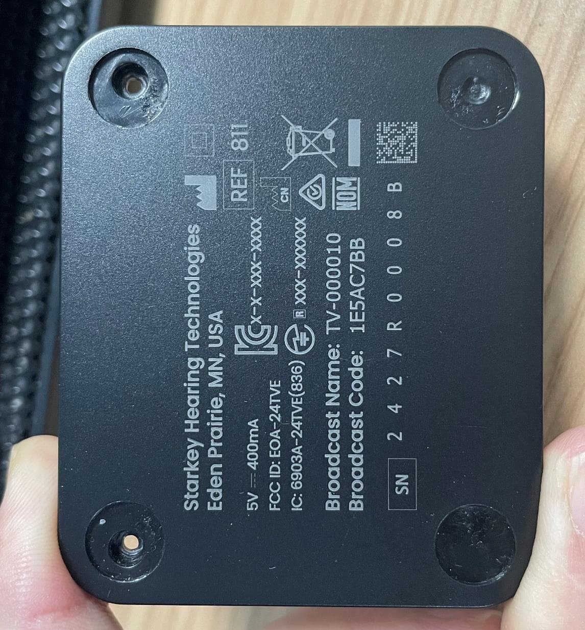
EOA-24TVE
Aug 18, 2024Starlink Edge TV
Equipment Class
DTS - Digital Transmission System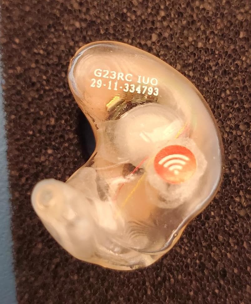
EOA-24EDGITERCH
Jul 17, 2024Edge AI ITE right
Equipment Class
DTS - Digital Transmission System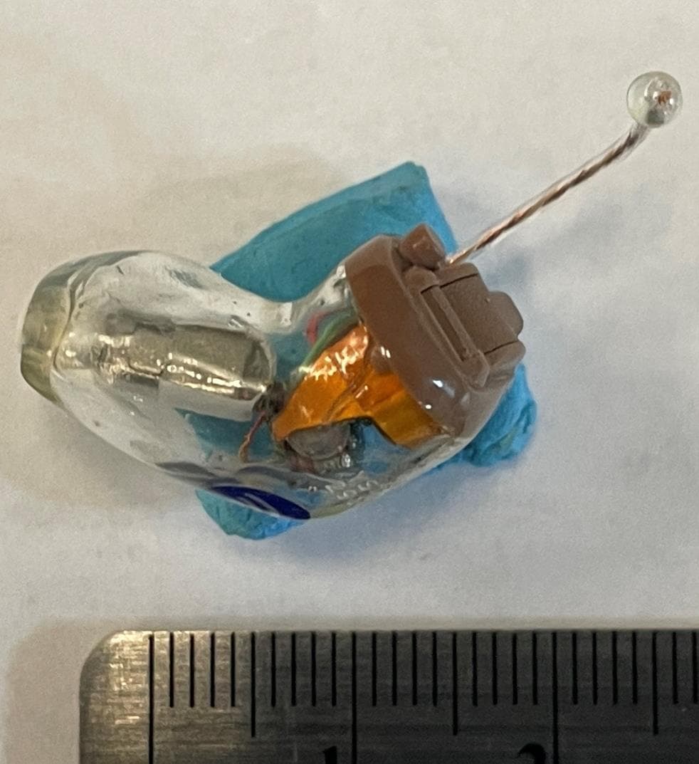
EOA-24EDGCIC
Jul 17, 2024Edge AI CIC
Equipment Class
DTS - Digital Transmission System
EOA-24EDGMRIC
Jul 17, 2024Edge AI mRIC R
Equipment Class
DTS - Digital Transmission System
EOA-24EDGITELCH
Jul 17, 2024Edge AI ITE left
Equipment Class
DTS - Digital Transmission System