EOA-TVG722210
Starkey Laboratories Inc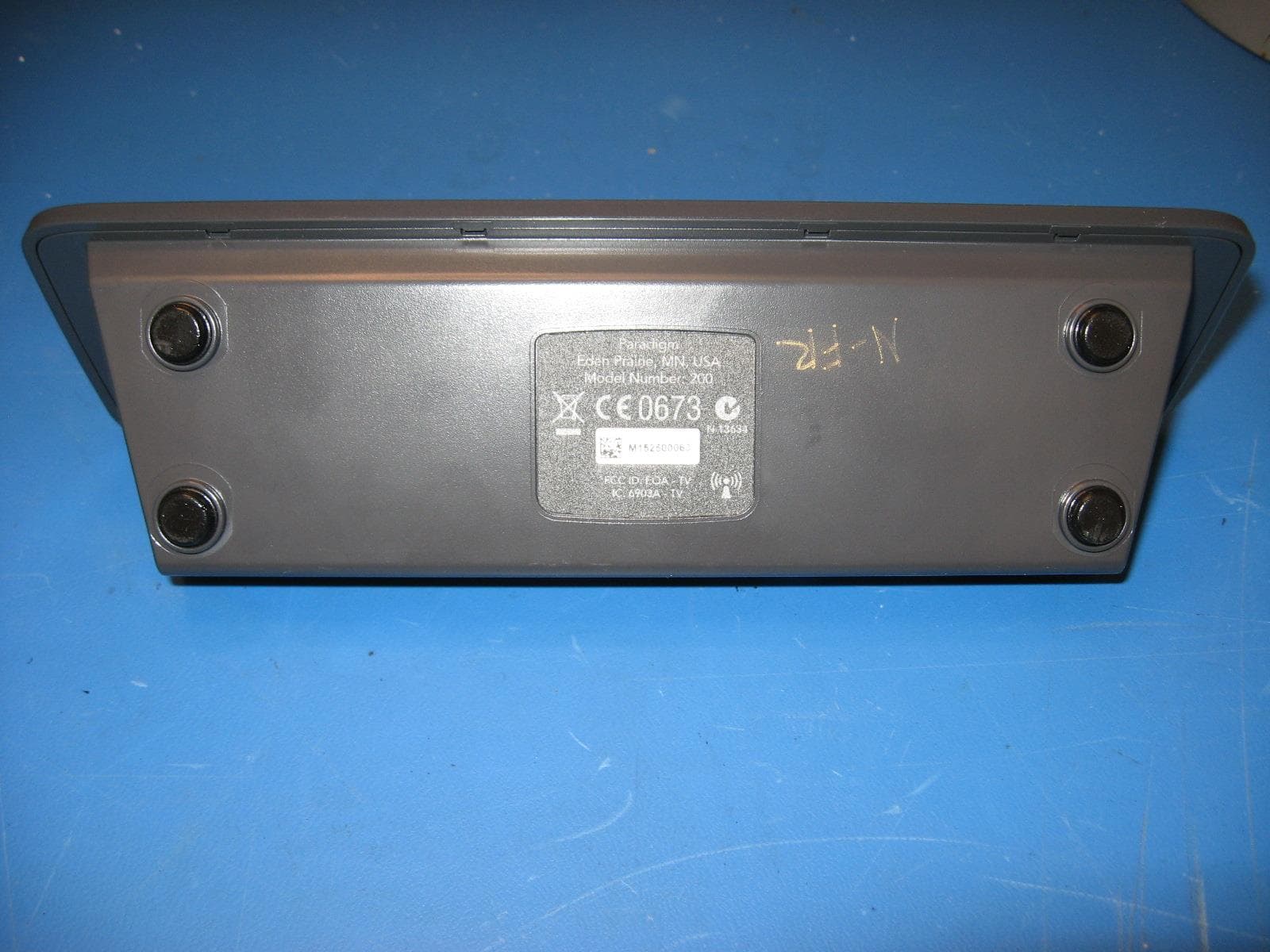
Click to zoom
Application Details
- Equipment Class
- DTS - Digital Transmission System
- Date of Grant
- Jul 16, 2015
- Application Purpose
- Original Equipment
- Date of Application
- Jul 16, 2015
- Equipment Note
- 210
- Frequency Range
- 902.80000000 - 926.75000000
- Company
- Starkey Laboratories Inc
- Country
- United States
Documents & Files
Document Text
Text extracted from the exhibit documents filed with the FCC. Open a document above to read the original.
Users Manual
MEDIA 23 SurfLink Media Controls Overview Power Streaming Activation Control Volume Control Microphone RCA Jacks Optical S/PDIF Monaural/Binaural Power TOSLINK Selection Back View Read This First SurfLink Media can be connected to most media sources, including televisions, radios, and MP3 players. This guide provides easy step-by-step instructions for connecting and using SurfLink Media. SurfLink Media must be powered on and connected to the desired media input before your hearing instruments can receive a signal. Only ONE of the following connection setups needs to be followed to begin the use of SurfLink Media. A variety of cables are included in this package to allow streaming from virtually any media source. Select the appropriate cable for your connection and store any unused cables. Package Contents •SurfLink Media •Power Adaptor •RCA Cable Microphone (1) RCA Jacks (2) An RCA audio cable is supplied. Optical TOSLINK Jack (3) A TOSLINK cable is not supplied. TOSLINK cables are available at most consumer electronic stores. S/PDIF Jack (4) An S/PDIF digital audio cable is not supplied. S/PDIF digital audio cables are available at most consumer electronic stores. Power (5) A micro-USB power cable is supplied. Insert the micro-USB connector into the Power port on SurfLink Media and connect the opposite end to the power outlet. 45 Connecting SurfLink Media and Media Source RCA Cable Installation (most common connection option) 1. Connect the red and white RCA cable plugs into the corresponding red and white RCA jacks (labeled 2) on SurfLink Media. 2. Select the signal type as Monaural or Binaural audio stream based on your hearing system confi guration. Monaural if you are wearing one hearing instrument. Binaural if you are wearing two hearing instruments. 3. Connect the opposite end of the red and white RCA cable jacks into the corresponding red and white RCA “AUDIO OUT” jacks on the media source. 4. Place SurfLink Media in a desired location that is in close proximity to the media source. Once SurfLink Media has been turned on it will begin to stream the audio signal. Connecting SurfLink Media and Media Source S/PDIF Installation 1. Connect the orange S/PDIF cable into the orange S/PDIF “AUDIO OUT” port (labeled 4) on the media source. 2. Select the signal type as Monaural or Binaural audio stream based on your hearing system confi guration. Monaural if you are wearing one hearing instrument. Binaural if you are wearing two hearing instruments. 3. Connect the opposite end of the orange S/PDIF cable into the orange S/PDIF port on the back of SurfLink Media. 4. Place SurfLink Media in a desired location that is in close proximity to the media source. Once SurfLink Media has been turned on it will begin to stream the audio signal. Power Streaming Activation Control Volume Control Microphone RCA Jacks Optical S/PDIF Monaural/Binaural Power TOSLINK Selection Optical S/PDIF Monaural/Binaural Power SLINK Selection Power Streaming Activation Control Volume Control Microphone RCA Jacks Optical S/PDIF Monaural/Binaural Power TOSLINK Selection Optical S/PDIF Monaural/Binaural Power SLINK Selection 67 Connecting SurfLink Media and Media Source Optical/TOSLINK Installation 1. Connect the optical/TOSLINK cable into the optical/TOSLINK “AUDIO OUT” port (labeled 3) on the media source. 2. Select the signal type as Monaural or Binaural audio stream based on your hearing system confi guration. Monaural if you are wearing one hearing instrument. Binaural if you are wearing two hearing instruments. 3. Connect the opposite end of the optical/ TOSLINK cable into the optical/TOSLINK port on the back of SurfLink Media. 4. Place SurfLink Media in a desired location that is in close proximity to the media source. Once SurfLink Media has been turned on it will begin to stream the audio signal. Connecting SurfLink Media and Media Source External Microphone Installation In the instance your television does not support the cable installation options listed on the previous pages, an external microphone can be used. 1. Connect the microphone cable into the microphone port (labeled 1) on the back of SurfLink Media. 2. Select the signal type as Monaural or Binaural audio stream based on your hearing system confi guration. Monaural if you are wearing one hearing instrument. Binaural if you are wearing two hearing instruments. 3. Place the microphone as close as possible to the speaker(s) of the desired media source. Once SurfLink Media has been turned on on it will begin to stream the audio signal. Television with External Microphone Confi guration Power Streaming Activation Control Volume Control Microphone RCA Jacks Optical S/PDIF Monaural/Binaural Power TOSLINK Selection Optical S/PDIF Monaural/Binaural Power SLINK Selection Power Streaming Activation Control Volume Control Microphone RCA Jacks Optical S/PDIF Monaural/Binaural Power TOSLINK Selection Optical S/PDIF Monaural/Binaural Power SLINK Selection 89 Turning On SurfLink Media 1. Plug the power adaptor into the wall socket or other power source. 2. Connect the power cord using the Power port (labeled 5) on the back of SurfLink Media. 3. Press the power button on the front of SurfLink Media. The power button glows blue when the device is on. Power Streaming Activation Control Volume Control Microphone RCA Jacks Optical S/PDIF Monaural/Binaural Power TOSLINK Selection Optical S/PDIF Monaural/Binaural Power SLINK Selection Power Streaming Activation Control Volume Control Microphone RCA Jacks Optical S/PDIF Monaural/Binaural Power TOSLINK Selection Power Activation SurfLink Media Controls Overview Power Streaming Activation Control Volume Control Microphone RCA Jacks Optical S/PDIF Monaural/Binaural Power TOSLINK Selection Front View Regulatory Notices SurfLink Media Controls Overview Volume Control The volume of the media source streaming to your hearing instruments can be adjusted by using the Volume Control. Slide your finger to the right to increase the volume…
Text truncated - open the document above for the full version.
External Photos
SurfLink G.722 Media Streamer External Photos Front Back/Top Bottom Note that label will be replaced with new label (see below) in same location Right Side Left Side
ID Label/Location Info
Bottom Note that label will be replaced with new label (see below) in same location
Internal Photos
SurfLink G.722 Media Streamer Internal Photos Case open, front face down Case open, back in foreground looking at front panel display circuit board Main circuit board, top view Main circuit board, bottom view
Operational Description
Starkey Laboratories 1 6600 Washington Avenue Eden Prairie, MN 55344 Date: ͛.6.201͙ Antenna Info This file must contain the following information: a) Describe compliance of the device with the antenna requirements of paragraph 15.203 of the FCC rules and Industry Canada RSS-Gen, Issue 4. The SurfLink Media i in compliance as the antenna is not detachabl e or replaceable, it is an integral part of the Printed Circuit Board Assembly itself. b) A list of antennas to be used with the transmitter. Include manufacturer, model number, gain (dBi), description (e.g. dipole, yagi, etc.), and impedance. Only o ne, the half wave dipole antenna that is an integral part of the Printed Circuit Board itself, +2dBi of gain, antenna impedance is 50 ohms. c) Drawing or photograph unless clear photos appear in the external photos exhibit Pict ure with explanation is on the next page. Starkey Laboratories 2 Radio IC shown inside orange box; RF signal path shown with red arrows; Antenna inside red boxes.
RF Exposure Info
This report must not be used to claim product certification, approval, or endorsement by NVLAP, NIST, or any agency of the federal government of the United States of America. This Report may only be duplicated in its entirety Starkey Laboratories, Inc. SurfLink Media Streamer FCC 2.1091:2015 Report # STAK0053.1 NVLAP Lab Code: 200881-0 CERTIFICATE OF TEST 2014-12-10 Product compliance is the responsibility of the client; therefore, the tests and equipment modes of operation represented in this report were agreed upon by the client, prior to testing. The results of this test pertain only to the sample(s) tested. The specific description is noted in each of the individual sections of the test report supporting this certificate of test. This report reflects only those tests from the referenced standards shown in the certificate of test. It does not include inspection or verification of labels, identification, marking or user information. Last Date of Test: June 30, 2015 Starkey Laboratories, Inc. Model: SurfLink Media Streamer Radio Equipment Testing Standards Specification Method FCC 2.1091:2015 KDB 447498 D01 General RF Exposure Guidance v05r02 Results Method Clause Test Description Applied Results Comments 7.1 Maximum Permissible Exposure Yes Pass Deviations From Test Standards None Approved By: Don Facteau, IT Manager Report No. STAK0053.12/9 REVISION HISTORY REV 2014.10.14 Revision Number Description Date Page Number 00 None Report No. STAK0053.13/9 ACCREDITATIONS AND AUTHORIZATIONS REV 2015.2.19 United States FCC - Designated by the FCC as a Telecommunications Certification Body (TCB). Certification chambers, Open Area Test Sites, and conducted measurement facilities are listed with the FCC. A2LA - Accredited by A2LA to ISO / IEC 17065 as a product certifier. This allows Northwest EMC to certify transmitters to FCC and IC specifications. NVLAP - Each laboratory is accredited by NVLAP to ISO 17025 Canada IC - Recognized by Industry Canada as a Certification Body (CB). Certification chambers and Open Area Test Sites are filed with IC. European Union European Commission – Validated by the European Commission as a Conformity Assessment Body (CAB) under the EMC directive and as a Notified Body under the R&TTE Directive. Australia/New Zealand ACMA - Recognized by ACMA as a CAB for the acceptance of test data. Korea MSIP / RRA - Recognized by KCC’s RRA as a CAB for the acceptance of test data. Japan VCCI - Associate Member of the VCCI. Conducted and radiated measurement facilities are registered. Taiwan BSMI – Recognized by BSMI as a CAB for the acceptance of test data. NCC - Recognized by NCC as a CAB for the acceptance of test data. Singapore IDA – Recognized by IDA as a CAB for the acceptance of test data. Israel MOC – Recognized by MOC as a CAB for the acceptance of test data. Hong Kong OFCA – Recognized by OFCA as a CAB for the acceptance of test data. Vietnam MIC – Recognized by MIC as a CAB for the acceptance of test data. SCOPE For details on the Scopes of our Accreditations, please visit: http://www.nwemc.com/accreditations/ http://gsi.nist.gov/global/docs/cabs/designations.html Report No. STAK0053.14/9 FACILITIES REV 2015.2.19 California Labs OC01-13 41 Tesla Irvine, CA 92618 (949) 861-8918 Minnesota Labs MN01-08, MN10 9349 W Broadway Ave. Brooklyn Park, MN 55445 (612)-638-5136 New York Labs NY01-04 4939 Jordan Rd. Elbridge, NY 13060 (315) 554-8214 Oregon Labs EV01-12 22975 NW Evergreen Pkwy Hillsboro, OR 97124 (503) 844-4066 Texas Labs TX01-09 3801 E Plano Pkwy Plano, TX 75074 (469) 304-5255 Washington Labs NC01-05 19201 120 th Ave NE Bothell, WA 9801 (425)984-6600 NVLAP NVLAP Lab Code: 200676-0 NVLAP Lab Code: 200881-0 NVLAP Lab Code: 200761-0 NVLAP Lab Code: 200630-0 NVLAP Lab Code:201049-0 NVLAP Lab Code: 200629-0 Industry Canada 2834B-1, 2834B-3 2834E-1 N/A 2834D-1, 2834D-2 2834G-1 2834F-1 BSMI SL2-IN-E-1154R SL2-IN-E-1152R N/A SL2-IN-E-1017 SL2-IN-E-1158R SL2-IN-E-1153R VCCI A-0029 A-0109 N/A A-0108 A-0201 A-0110 Recognized Phase I CAB for ACMA, BSMI, IDA, KCC/RRA, MIC, MOC, NCC, OFCA US0158 US0175 N/A US0017 US0191 US0157 Report No. STAK0053.15/9 PRODUCT DESCRIPTION 2014-12-10 Client and Equipment Under Test (EUT) Information Company Name: Starkey Laboratories, Inc. Address: 6600 Washington Ave. South City, State, Zip: Eden Prairie, MN 55344 Test Requested By: Bill Mitchell Model: SurfLink Media Streamer Evaluation Date: June 30, 2015 Information Provided by the Party Requesting the Test Functional Description of the EUT: Wireless media streamer that can accept various wired audio inputs from a TV or other audio sources for wireless transmission to hearing aids. The transmitter is a low power, short-range device operating in the 902 - 928 MHz range. Testing Objective: To demonstrate compliance with FCC requirements for RF exposure for 2.1091 mobile devices. Report No. STAK0053.16/9 MAXIMUM PERMISSIBLE EXPOSURE (MPE) WTD.2014.12.17 OVERVIEW Human exposure to RF emissions from mobile devices (47 CFR §2.1091) may be evaluated based on the MPE limits adopted by the FCC for electric and magnetic field strength and/or power density, as appropriate, since exposures are assumed to occur at distances of 20 cm or more from persons. ANSI C95.1-2005 specifies a minimum separation distance of 20 cm for performing reliable field measurements to determine adherence to MPE limits. If the minimum separation distance between a transmitter and nearby persons is more than 20 cm under normal operating conditions, compliance with MPE limits may be determined at such distance from the transmitter. When applicable, operation instructions and prominent warning labels may be used to alert the exposed persons to maintain a specified distance from the transmitter or to limit their exposure durations and usage conditions to ensure compliance. If the use of warning labels on a transmitter is not effective or desirable, the alternative of performing SAR evaluation with the device at its closest range to p…
Text truncated - open the document above for the full version.
Test Report
This report must not be used to claim product certification, approval, or endorsement by NVLAP, NIST, or any agency of the federal government of the United States of America. This Report may only be duplicated in its entirety Starkey Laboratories, Inc. SurfLink Media Streamer FCC 15.207:2015 FCC 15.247:2015 Report # STAK0053 NVLAP Lab Code: 200881-0 CERTIFICATE OF TEST 2014-12-10 Product compliance is the responsibility of the client; therefore, the tests and equipment modes of operation represented in this report were agreed upon by the client, prior to testing. The results of this test pertain only to the sample(s) tested. The specific description is noted in each of the individual sections of the test report supporting this certificate of test. This report reflects only those tests from the referenced standards shown in the certificate of test. It does not include inspection or verification of labels, identification, marking or user information. Last Date of Test: June 19, 2015 Starkey Laboratories, Inc. Model: SurfLink Media Streamer Radio Equipment Testing Standards Specification Method FCC 15.207:2015 ANSI C63.10:2009 FCC 15.247:2015 ANSI C63.10:2009 Results Method Clause Test Description Applied Results Comments 6.2 Powerline Conducted Emissions Yes Pass 6.5, 6.6 Spurious Radiated Emissions Yes Pass 6.7 Band Edge Compliance Yes Pass 6.7 Spurious Conducted Emissions Yes Pass 6.9.1 Occupied Bandwidth Yes Pass 6.10.2 Output Power Yes Pass 6.11.2 Power Spectral Density Yes Pass 7.5 Duty Cycle Yes N/A Deviations From Test Standards None Approved By: Tim O'Shea, Operations Manager Report No. STAK0053.22/48 REVISION HISTORY REV 2014.10.14 Revision Number Description Date Page Number 00 None Report No. STAK0053.23/48 ACCREDITATIONS AND AUTHORIZATIONS REV 2015.2.19 United States FCC - Designated by the FCC as a Telecommunications Certification Body (TCB). Certification chambers, Open Area Test Sites, and conducted measurement facilities are listed with the FCC. A2LA - Accredited by A2LA to ISO / IEC 17065 as a product certifier. This allows Northwest EMC to certify transmitters to FCC and IC specifications. NVLAP - Each laboratory is accredited by NVLAP to ISO 17025 Canada IC - Recognized by Industry Canada as a Certification Body (CB). Certification chambers and Open Area Test Sites are filed with IC. European Union European Commission – Validated by the European Commission as a Conformity Assessment Body (CAB) under the EMC directive and as a Notified Body under the R&TTE Directive. Australia/New Zealand ACMA - Recognized by ACMA as a CAB for the acceptance of test data. Korea MSIP / RRA - Recognized by KCC’s RRA as a CAB for the acceptance of test data. Japan VCCI - Associate Member of the VCCI. Conducted and radiated measurement facilities are registered. Taiwan BSMI – Recognized by BSMI as a CAB for the acceptance of test data. NCC - Recognized by NCC as a CAB for the acceptance of test data. Singapore IDA – Recognized by IDA as a CAB for the acceptance of test data. Israel MOC – Recognized by MOC as a CAB for the acceptance of test data. Hong Kong OFCA – Recognized by OFCA as a CAB for the acceptance of test data. Vietnam MIC – Recognized by MIC as a CAB for the acceptance of test data. SCOPE For details on the Scopes of our Accreditations, please visit: http://www.nwemc.com/accreditations/ http://gsi.nist.gov/global/docs/cabs/designations.html Report No. STAK0053.24/48 MEASUREMENT UNCERTAINTY TMU.2014.12.03 Measurement Uncertainty When a measurement is made, the result will be different from the true or theoretically correct value. The difference is the result of tolerances in the measurement system that cannot be completely eliminated. To the extent that technology allows us, it has been our aim to minimize this error. Measurement uncertainty is a statistical expression of measurement error qualified by a probability distribution. A measurement uncertainty estimation has been performed for each test per our internal quality document WP 342. The estimation is used to compare the measured result with its "true" or theoretically correct value. The expanded measurement uncertainty (K=2) for each test is on each data sheet. Our measurement data meets or exceeds the measurement uncertainty requirements of the applicable specification; therefore, the test data can be compared directly to the specification limit to determine compliance. The calculations for estimating measurement uncertainty are based upon ETSI TR 100 028 (or CISPR 16-4-2 as applicable), and are available upon request. The following table represents the Measurement Uncertainty (MU) budgets for each of the tests that may be contained in this report. Test + MU - MU Frequency Accuracy (Hz) 0.0007% -0.0007% Amplitude Accuracy (dB) 1.2 dB -1.2 dB Conducted Power (dB) 0.3 dB -0.3 dB Radiated Power via Substitution (dB) 0.7 dB -0.7 dB Temperature (degrees C) 0.7°C -0.7°C Humidity (% RH) 2.5% RH -2.5% RH Voltage (AC) 1.0% -1.0% Voltage (DC) 0.7% -0.7% Field Strength (dB) 4.7 dB -4.7 dB AC Powerline Conducted Emissions (dB) 2.9 dB -2.9 dB Report No. STAK0053.25/48 FACILITIES REV 2015.2.19 California Labs OC01-13 41 Tesla Irvine, CA 92618 (949) 861-8918 Minnesota Labs MN01-08, MN10 9349 W Broadway Ave. Brooklyn Park, MN 55445 (612)-638-5136 New York Labs NY01-04 4939 Jordan Rd. Elbridge, NY 13060 (315) 554-8214 Oregon Labs EV01-12 22975 NW Evergreen Pkwy Hillsboro, OR 97124 (503) 844-4066 Texas Labs TX01-09 3801 E Plano Pkwy Plano, TX 75074 (469) 304-5255 Washington Labs NC01-05 19201 120 th Ave NE Bothell, WA 9801 (425)984-6600 NVLAP NVLAP Lab Code: 200676-0 NVLAP Lab Code: 200881-0 NVLAP Lab Code: 200761-0 NVLAP Lab Code: 200630-0 NVLAP Lab Code:201049-0 NVLAP Lab Code: 200629-0 Industry Canada 2834B-1, 2834B-3 2834E-1 N/A 2834D-1, 2834D-2 2834G-1 2834F-1 BSMI SL2-IN-E-1154R SL2-IN-E-1152R N/A SL2-IN-E-1017 SL2-IN-E-1158R SL2-IN-E-1153R VCCI A-0029 A-0109 N/A A-0108 A-0201 A-0110 Recognized Phase I CAB for ACMA, BSMI, IDA, KCC/RRA…
Text truncated - open the document above for the full version.
Test Setup Photos
POWERLINE CONDUCTED EMISSIONS WTD.2015.05.26 PSA-ESCI 2015.03.03, EmiR5 2015.05.29 photo SE 001.jpg SE 002.jpg SPURIOUS RADIATED EMISSIONS PSA-ESCI 2015.03.03 Report No. STAK0053.2 Photos Only2/9 photo SE 003.jpg SE 004.jpg SPURIOUS RADIATED EMISSIONS PSA-ESCI 2015.03.03 Report No. STAK0053.2 Photos Only3/9 photo SE 005.jpg SPURIOUS RADIATED EMISSIONS PSA-ESCI 2015.03.03 Report No. STAK0053.2 Photos Only4/9 XMit 2015.01.14 DIRECT 001.jpg DIRECT 002.jpg BAND EDGE COMPLIANCE Report No. STAK0053.2 Photos Only5/9 XMit 2015.01.14 DIRECT 001.jpg DIRECT 002.jpg SPURIOUS CONDUCTED EMISSIONS Report No. STAK0053.2 Photos Only6/9 XMit 2015.01.14 DIRECT 001.jpg DIRECT 002.jpg OCCUPIED BANDWIDTH Report No. STAK0053.2 Photos Only7/9 XMit 2015.01.14 DIRECT 001.jpg DIRECT 002.jpg OUTPUT POWER Report No. STAK0053.2 Photos Only8/9 XMit 2015.01.14 DIRECT 001.jpg DIRECT 002.jpg POWER SPECTRAL DENSITY Report No. STAK0053.2 Photos Only9/9
Contact Information
Applicant
William John Mitchell(Principal Regulatory Affairs Engineer)
Test Firm
Northwest EMC, Inc.Greg Kiemel
Technical Specifications
| # | Rule Parts | Frequency Range | Power Output |
|---|---|---|---|
| 1 | 15C | 902.8 MHz - 926.75 MHz | 27.90 mW |
Other Applications from Starkey Laboratories Inc
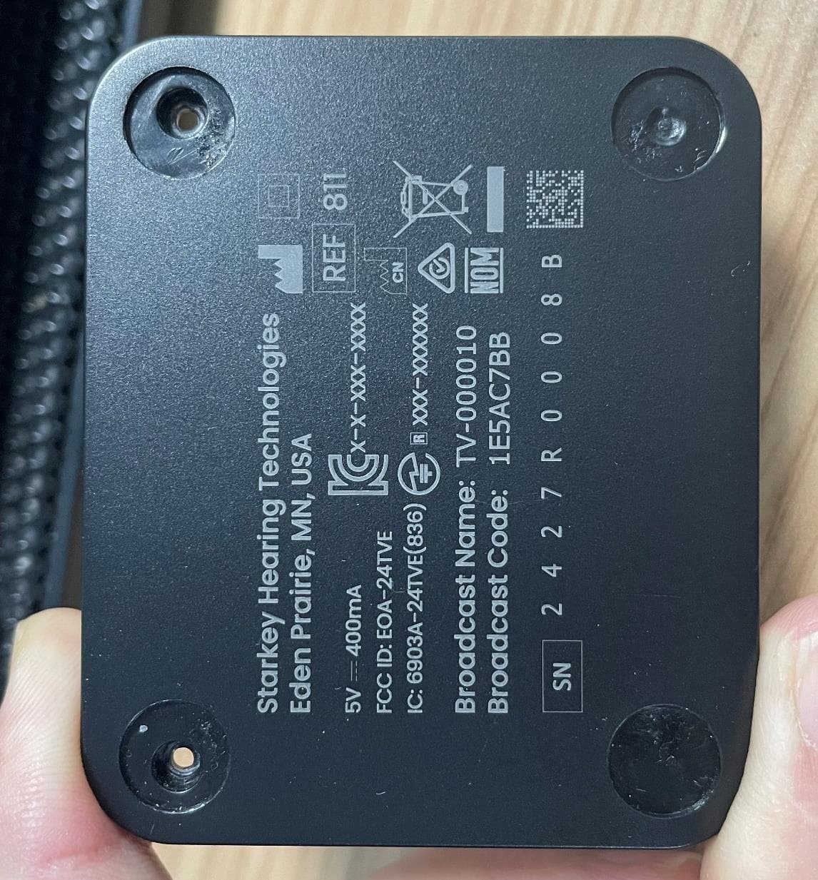
EOA-24TVE
Aug 18, 2024Starlink Edge TV
Equipment Class
DTS - Digital Transmission System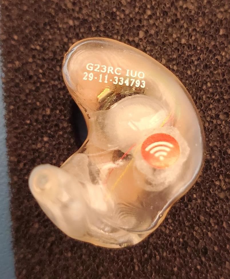
EOA-24EDGITERCH
Jul 17, 2024Edge AI ITE right
Equipment Class
DTS - Digital Transmission System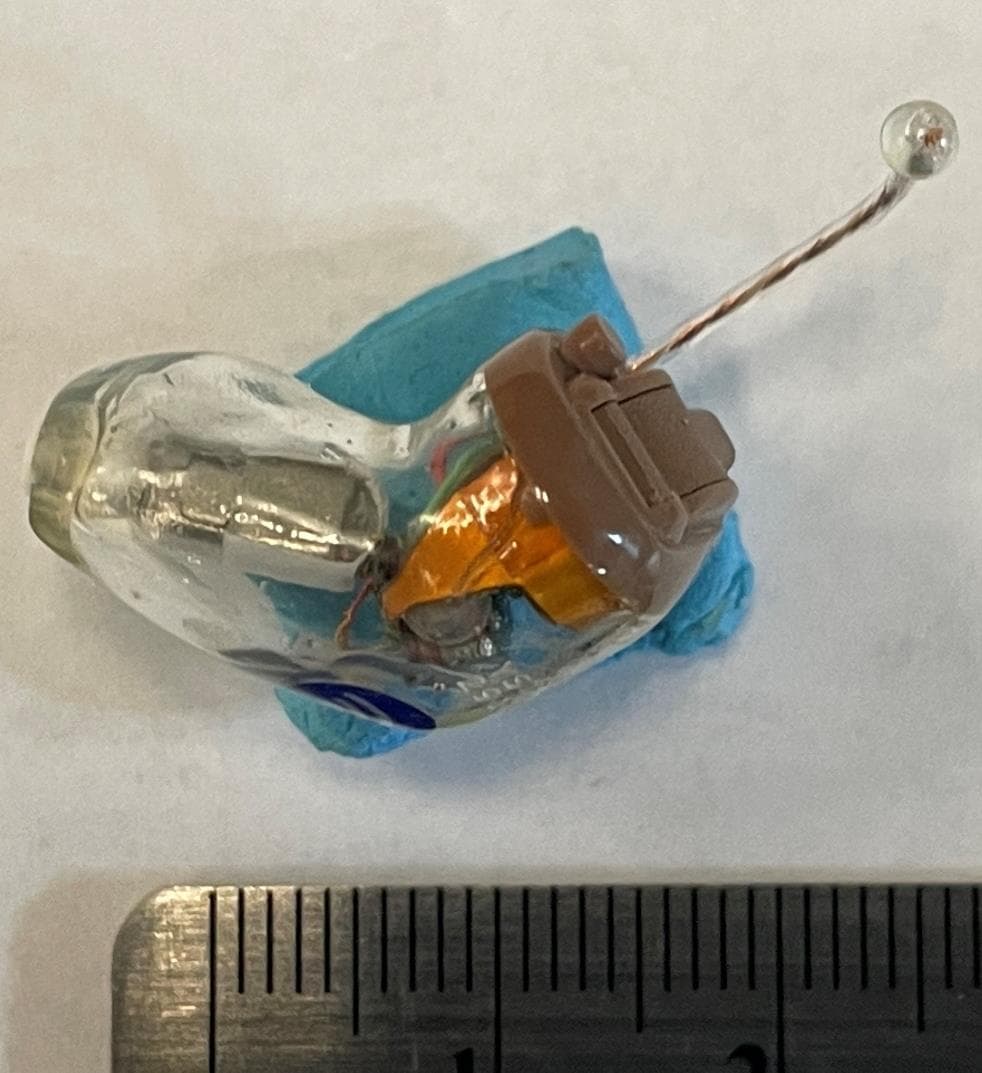
EOA-24EDGCIC
Jul 17, 2024Edge AI CIC
Equipment Class
DTS - Digital Transmission System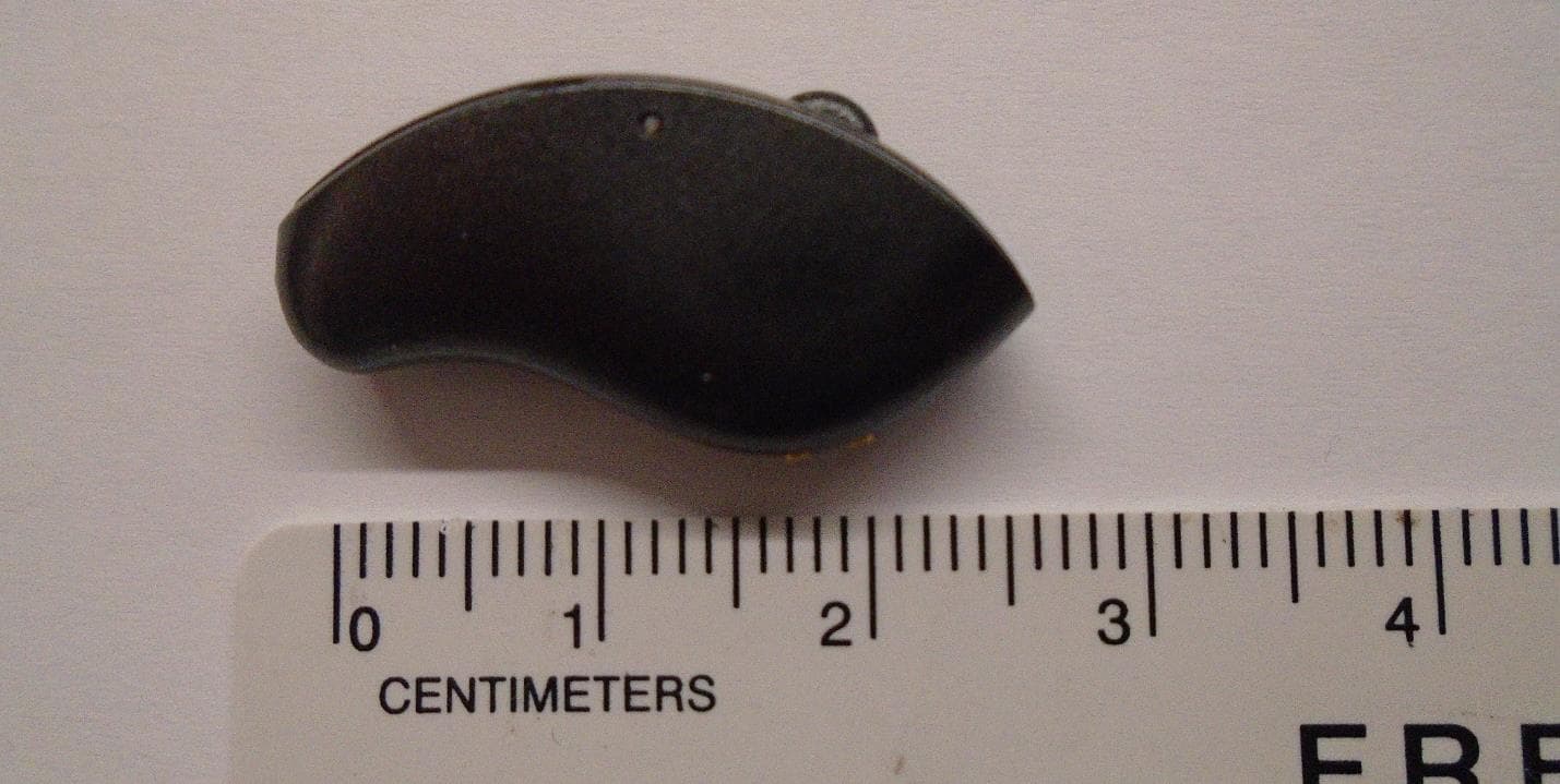
EOA-24EDGMRIC
Jul 17, 2024Edge AI mRIC R
Equipment Class
DTS - Digital Transmission System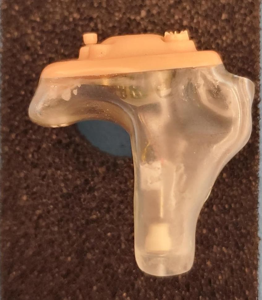
EOA-24EDGITELCH
Jul 17, 2024Edge AI ITE left
Equipment Class
DTS - Digital Transmission System