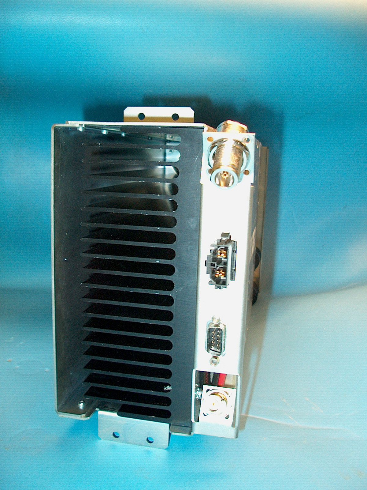
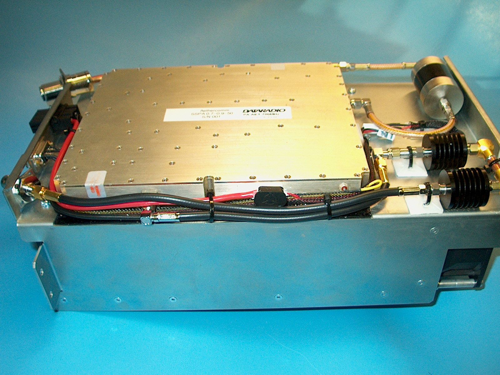
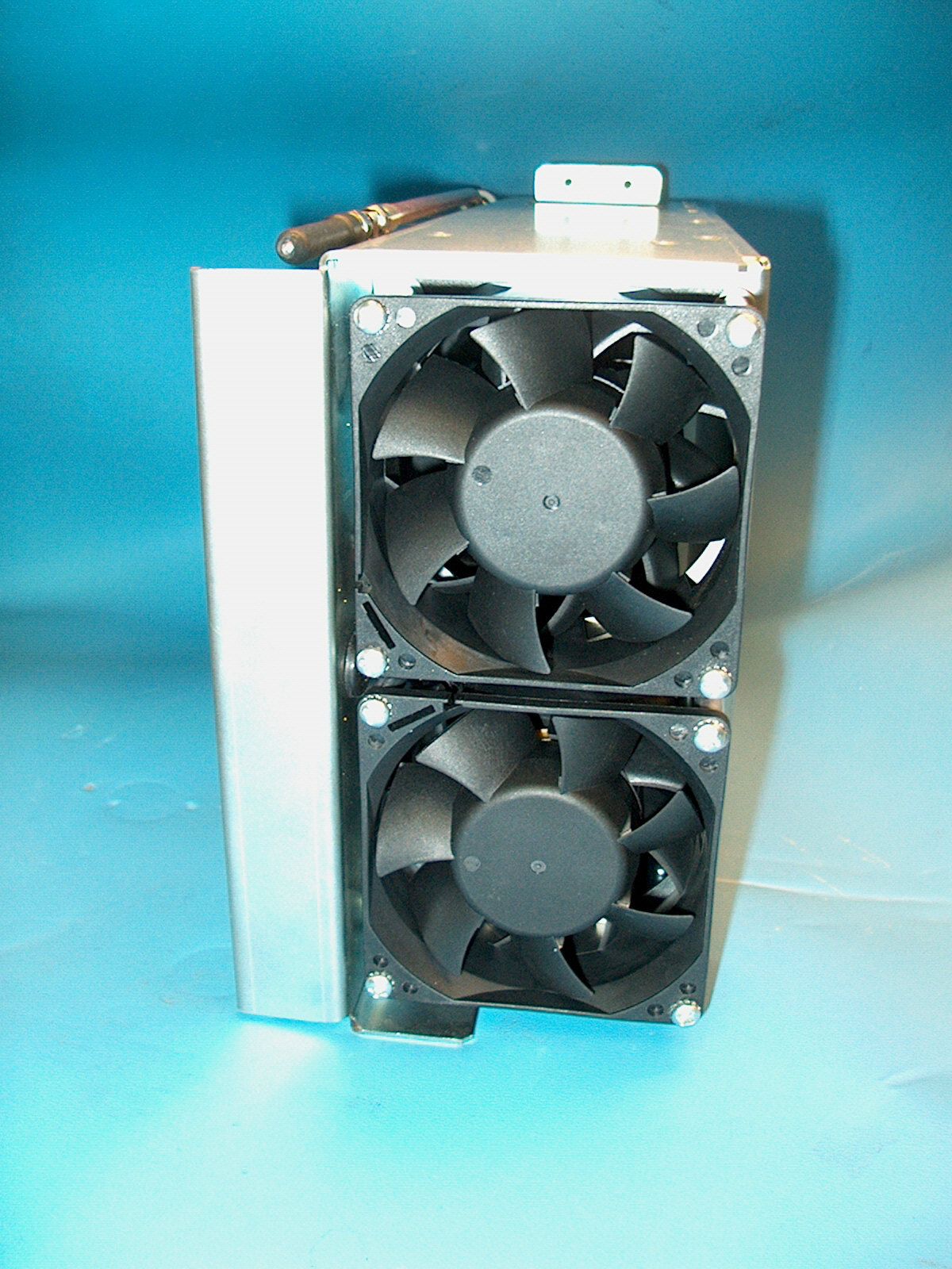
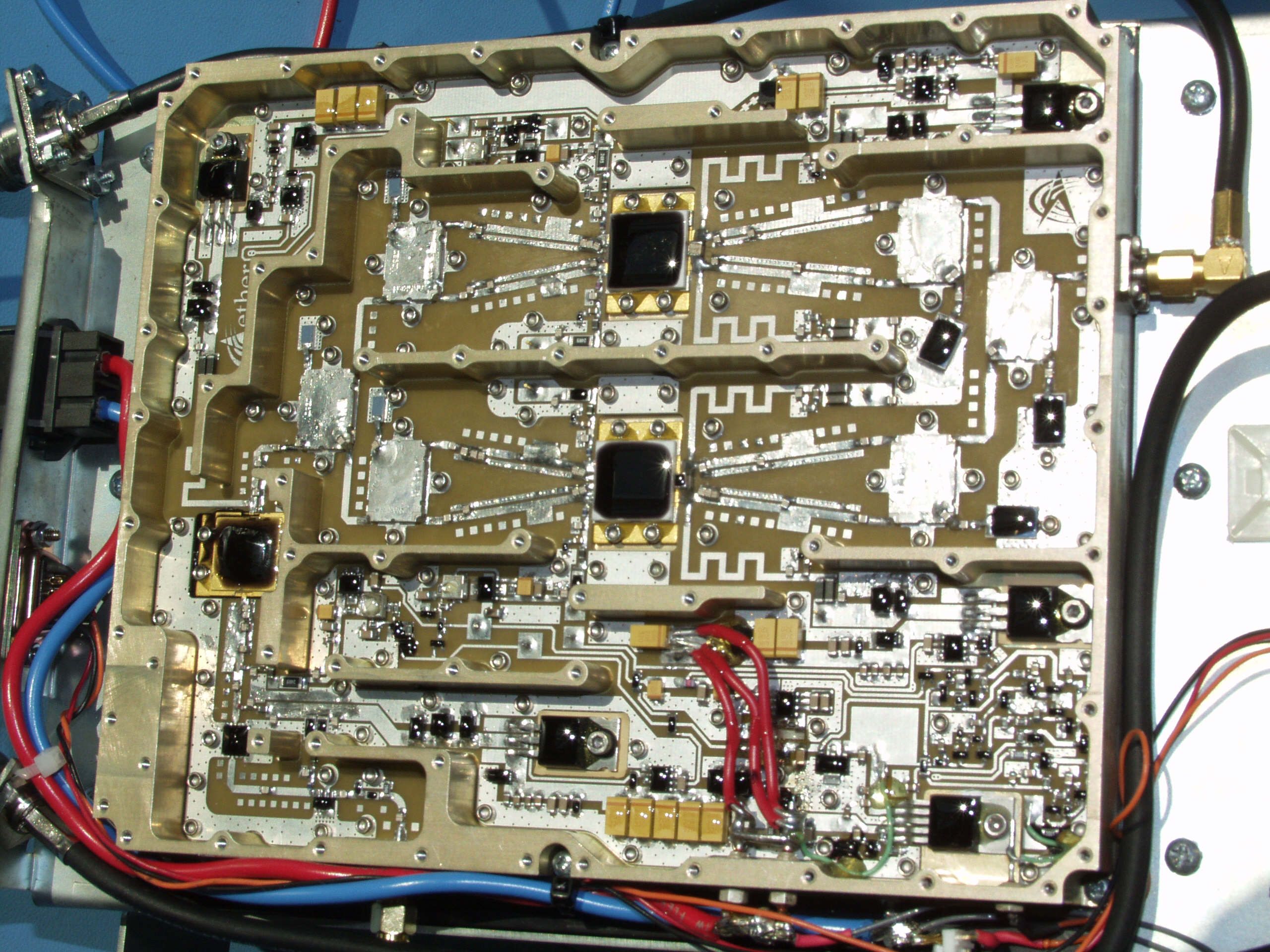
EOTBDP3-AETAET Amplifier
CALAMP WIRELESS NETWORKS INC.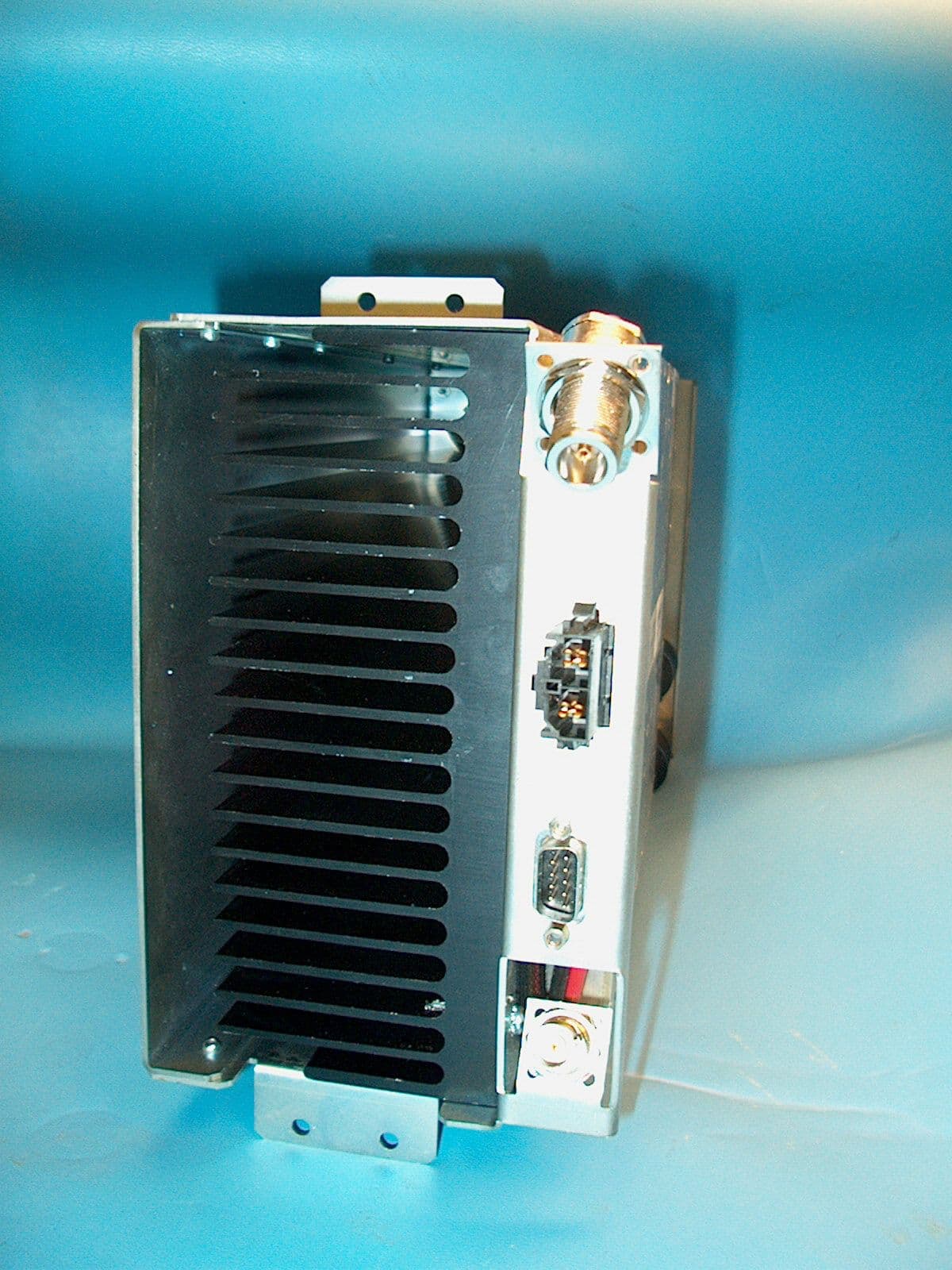
Click to zoom
Application Details
- Equipment Class
- AMP - Amplifier
- Date of Grant
- Mar 16, 2005
- Application Purpose
- Original Equipment
- Date of Application
- Jan 13, 2005
- Equipment Note
- AET Amplifier
- Frequency Range
- 762.00000000 - 773.00000000
- Country
- United States
Documents & Files
Document Text
Text extracted from the exhibit documents filed with the FCC. Open a document above to read the original.
Users Manual
Paragon-III (700 MHz) Data Base Station Technical Manual Version 0.02 (preliminary) The entire contents of this manual and the Radio Installation Software described in this manual are copyright 2004 by DATARADIO Inc. Copyright DATARADIO Inc. April 2004 Part no.: 120 20191-001 120 20191-002 Paragon-III Technical Manual ii 1. PRODUCT OVERVIEW ...................................................................................................................................1 1.1 I NTENDED AUDIENCE........................................................................................................................................1 1.2 G ENERAL DESCRIPTION.....................................................................................................................................1 1.2.1 Features:..................................................................................................................................................2 1.3 F ACTORY TECHNICAL SUPPORT........................................................................................................................3 1.4 P RODUCT WARRANTY.......................................................................................................................................4 1.5 R EPLACEMENT PARTS.......................................................................................................................................4 1.5.1 Factory Repair.........................................................................................................................................4 1.6 P ACKAGING.......................................................................................................................................................4 2. INSTALLATION................................................................................................................................................5 2.1 O VERVIEW........................................................................................................................................................5 2.2 L OCATION.........................................................................................................................................................5 2.3 F RONT VIEW: ....................................................................................................................................................5 2.4 R EAR VIEWS: ....................................................................................................................................................6 2.5 E LECTRICAL......................................................................................................................................................8 2.5.1 Paragon-III Assembly Power ..................................................................................................................8 2.6 A NTENNA........................................................................................................................................................10 2.6.1 Overview ................................................................................................................................................10 2.6.2 Cabling and Connection ........................................................................................................................10 2.7 C OMPLETING THE PHYSICAL INSTALLATION....................................................................................................10 2.8 C HECKING OUT NORMAL OPERATION.............................................................................................................10 3. OPERATING DESCRIPTION .......................................................................................................................11 3.1 R ADIO ASSEMBLY...........................................................................................................................................11 3.1.1 Receiver module....................................................................................................................................11 3.1.2 5W Transmitter module .........................................................................................................................12 3.1.3 50W Transmitter module .......................................................................................................................12 3.1.4 BDLC-III module ...................................................................................................................................13 3.1.5 Speaker panel ........................................................................................................................................13 3.1.6 Dual Power Supply module ...................................................................................................................14 3.1.7 Radio Backplane Assembly....................................................................................................................15 4. TROUBLE-SHOOTING AND TESTING .....................................................................................................16 4.1 E QUIPMENT REQUIRED....................................................................................................................................16 4.2 R ECOMMENDED CHECKS.................................................................................................................................16 4.3 A DDITIONAL TEST DETAILS.............................................................................................................................20 4.3.1 RF Data Link Test..................................................................................................................................20 5. RADIO PROGRAMMING AND ADJUSTMENTS .....................................................................................21 5.1 S ERIES II RADIO PROGRAMMING................................…
Text truncated - open the document above for the full version.
Cover Letter(s)
FCC ID EOTBDP3-AET Applicant Dataradio Inc. Request for Confidentiality for: Annex A2- Digital Modulation Techniques of the input signal for ----F1D emission designator . Annex B - block diagrams and operational description Annex C -active parts list Annexes D1 and D2 -Schematics The request for confidentiality as per FCC 0.459 (a) refers to the above mentioned exhibits uploaded as Annexes of the report. These parts contains proprietary detail of the internal workings of the product, the publication of which could be detrimental to our firm if taken out of context by competitors. For these reasons we request that the above mentioned documents be made confidential as per FCC 0.457(d)(2). Best Regards, Norman Pearl VP Engineering Dataradio Inc
Test Report
Assessment of Compliance for Measurement of Field Strength of Spurious Radiation in accordance with the FCC Rules & Regulations Part 2.1053 and 90.543 and 27.53 700 MHz band base station power amplifier Aethercomm Dataradio. 51 Spectrum Way Nepean ON K2R 1E6 Tel: (613) 820-2730 Fax: (613) 820-4161 email: [email protected] October 2004 APREL Project No.: DATB-AETHERCOMM-5072 E E n n g g i i n n e e e e r r i i n n g g R R e e p p o o r r t t Subject: Measurement of Field Strength of Spurious Radiation in accordance with the FCC Rules & Regulations Part 2.1053, 90.543 and 27.53 FCC ID: EOTBDP3-AET Equipment: 700 MHz band base station power amplifier Model: BDP3-87S-170502A-AET option Client: Dataradio Suite 200, 5500 Royalmount Ave. Town of Mount Royal, Quebec CANADA, H4P 1H7 Project #: DATB-AETHERCOMM-5072 Prepared By: APREL Laboratories, Regulatory Compliance Division 51 Spectrum Way Nepean, Ontario K2R 1E6 © October 2004 Page 3 APREL Project No: DATB-AETHERCOMM-5072 This report shall not be reproduced, except in full, without the express written approval of APREL Laboratories Consulting * Research * Training * Certification Testing Since 1981 FCC ID: EOTBDP3-AET Applicant: Dataradio Equipment: 700 MHz band base station power amplifier Model: BDP3-87S-170502A-AET option Standard: FCC Rules and Regulations Part 2.1053, 90.543(c) and 27.53(d) (3) ENGINEERING SUMMARY This report contains the results of Field Strength of Spurious Radiation measurement performed on a Dataradio 700 MHz band base station power amplifier model BDP3-87S-170502A-AET option, in accordance with the FCC Rules and Regulations Parts 2.1053, 90.543(c) and 27.53(d)(3). The measurements were carried out using substitution method as radiated. The product was evaluated for spurious radiation when it was set at the highest power. Test configuration: BDP3-87S-170502A-AET option was tested as a stand-alone unit. This report presents test data for frequency band 767.025-772.975 MHz & 762.025-763.925 MHz The results presented in this report relate only to the sample tested. Summary of the Results Test Description Page No. Test Set-up Figure No. Results Summary Field Strength of Spurious Radiation Ref. Paragraph 2.1053 and 90.543 (c), 27.53(d)(3) 8 1 Passed © October 2004 Page 4 APREL Project No: DATB-AETHERCOMM-5072 This report shall not be reproduced, except in full, without the express written approval of APREL Laboratories Consulting * Research * Training * Certification Testing Since 1981 INTRODUCTION General This report describes the results of the Field Strength of Spurious Radiation measurement conducted on a DATARADIO 700 MHz band base station power amplifier, model BDP3-87S- 170502A-AET option, herein referred to as DUI (Device Under Investigation). Test Facility The tests were performed for Dataradio by APREL Laboratories at APREL’s EMI facility located in Nepean, Ontario, Canada. The laboratory operates an (3m and 10m) Open Area Test Site (OATS). The measurement facility is calibrated in accordance with ANSI C63.4-1992. A description of the measurement facility in accordance with the radiated and AC line conducted test site criteria per ANSI C63.4-1992 is on file with the Federal Communications Commission and is in compliance with the requirements of Section 2.948 of the Commissions rules and regulations. APREL’s registration number is 90416. APREL’S Industry Canada Approval number for the OATS is IC2068. APREL is accredited by Standard Council of Canada under ISO 17025. Standard The evaluation and analysis were conducted in accordance with FCC Rules and Regulations Parts 2.1053, 90.543(c) and 27.53(d)(3). Personnel: The equipment was tested by Roman Kuleba, EMC Engineer, methodology developed and the report was written by Jayanta (Jay) K. Sarkar, Technical Director, Standards and Certification. Test Equipment The test equipment used during the evaluation is listed in Appendix A with calibration due dates. Environmental Conditions Measurements were conducted in open area test site. Temperature: 24°C ± 2, Relative Humidity: 30 - 50 % , Air Pressure: 101 kPa ± 3. © October 2004 Page 5 APREL Project No: DATB-AETHERCOMM-5072 This report shall not be reproduced, except in full, without the express written approval of APREL Laboratories Consulting * Research * Training * Certification Testing Since 1981 FCC SUBMISSION INFORMATION FCC ID: EOTBDP3-AET Equipment type: 700 MHz band base station power amplifier Model: BDP3-87S-170502A-AET option For: Certification Applicant: Dataradio Suite 200, 5500 Royalmount Ave. Town of Mount Royal, Quebec CANADA, H4P 1H7 Manufacturer: Dataradio Suite 200, 5500 Royalmount Ave. Town of Mount Royal, Quebec CANADA, H4P 1H7 Evaluated by: APREL Laboratories 51 Spectrum Way Nepean, Ontario Canada K2R 1E6 © October 2004 Page 6 APREL Project No: DATB-AETHERCOMM-5072 This report shall not be reproduced, except in full, without the express written approval of APREL Laboratories Consulting * Research * Training * Certification Testing Since 1981 MANUFACTURER’S DATA FCC ID: EOTBDP3-AET Equipment Type: 700 MHz band base station power amplifier Model: BDP3-87S-170502A-AET option Reference: FCC Rules and Regulations Parts 2.1053, 90.543(c) and 27.53(d) (3) Manufacturer: Dataradio Development Stage of Unit: Pre-Production © October 2004 Page 7 APREL Project No: DATB-AETHERCOMM-5072 This report shall not be reproduced, except in full, without the express written approval of APREL Laboratories Consulting * Research * Training * Certification Testing Since 1981 Test: Field Strength of Spurious Radiation Ref: FCC Parts 2.1053 and 90.543 (c), 27.53(d) (3) Frequency Band: 767.025-773.975 MHz (Part 90.543) and 762.025-764.925 MHz (Part 27.53(d)) Criteria: The radiated spurious emissions shall be attenuated below the maximum level of Emissions of the carrier frequency in accordance with the following formula: Spurious attenuation in dB=43+10log10 (P). (Thus the effective limit is -13dBm) Set-up: See Figure 1.a Conditi…
Text truncated - open the document above for the full version.
Test Report
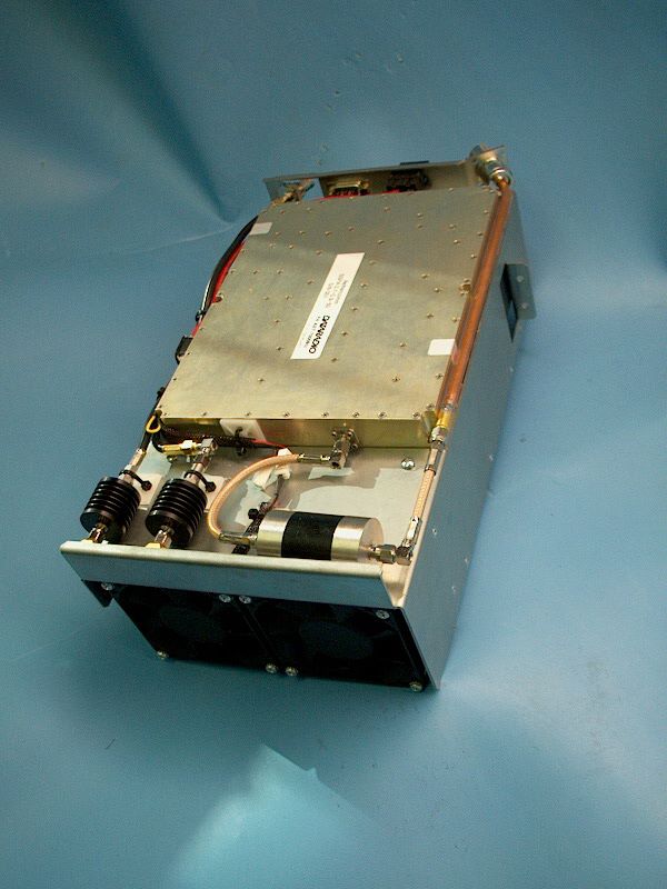
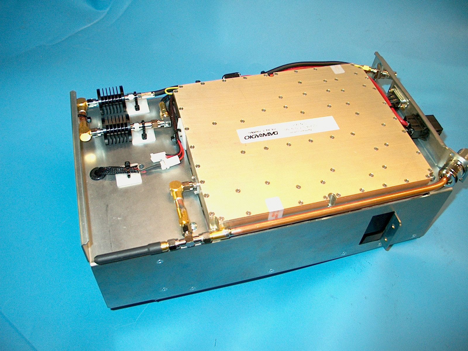
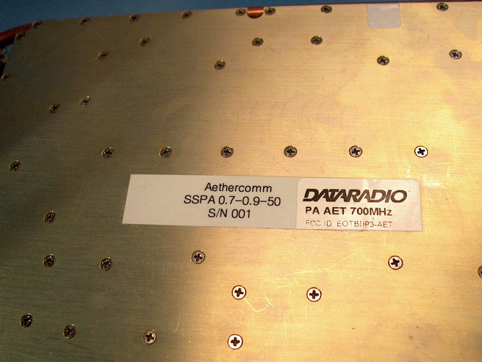
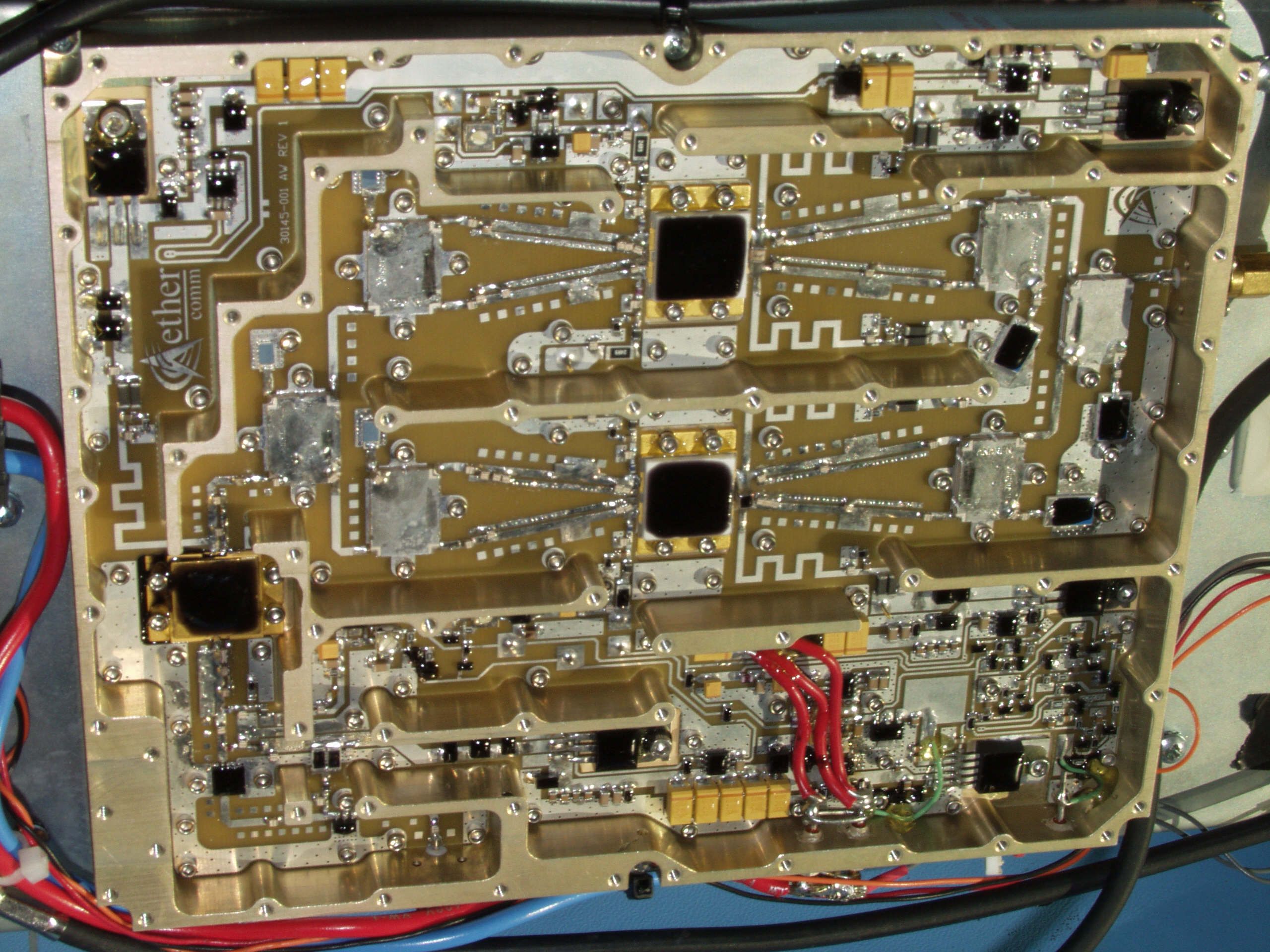
Engineering Exhibit in Support of Certification FCC Form 731 for the 700MHz Power Amplifier for BDP3 Digital Base Station FCC ID: EOTBDP3-AET Trade Name: AET Amplifier Module January 20, 2005 EOTBDP3 – AET 50W PA module of 700MHz BDP3 base station- Engineering Report - body Page 2 of 7 156-90000-700 Dataradio© FCC submission AFFIDAVIT The technical data included in this report has been accumulated through tests that were performed by me or by engineers under my direction. To the best of my knowledge, all of the data is true and correct. _______________________________________________________ Norman D Pearl Vice-president Engineering, Dataradio Inc. EOTBDP3 – AET 50W PA module of 700MHz BDP3 base station- Engineering Report - body Page 3 of 7 156-90000-700 Dataradio© FCC submission Dataradio Inc. Montreal, Canada ENGINEERING STATEMENT OF CONSTANTIN PINTILEI The application consisting of the attached engineering exhibit and associated FCC form 731 has been prepared in support of a request for Certification for the PA module of the Dataradio BDP3 digital base station. The Power Amplifier will operate in the frequency range of 762-773 MHz in Transmit and will yield 50W RF power for 10dB of fixed amplification. Dataradio, Canada, will buy the OEM SSPA power module from Aethercomm, St Marcos, CA, with the part# SSPA0.7-0.9-50. Dataradio will install the SSPA module into the PA module of the base station and perform final assembly and tests. The PA module will be used with other 5W FCC approved exciters from Dataradio. The unit is identified by the Dataradio part number BDP3-87S-RB050SM (part number is detailed in page 6) and marketed under the Model name BDP3. The PA module will be identified by the FCC number EOTBDP3- AET. The Power Amplifier operates pursuant to Part(s) 90 and 27of the Rules and Regulations. The RF power is adjustable in manufacturer’s premises from 12.5-50 watts and its nominal power is 50W. EXISTING CONDITIONS The unit utilized for these Certification measurements was a prototype built from production grade OEM components with worst-case output filtration (closed half-wave shunt resonator). The PA is designed to operate in single carrier mode only. There are no active control/feedback loops within the amplifier module. The suppression of the harmonics is enhanced through the use of a filtration block which yields a margin of at least 20dB from the limit. PROPOSED CONDITIONS It is proposed to grant the Dataradio BDP3-AET 50W, 10dB Power Amplifier module for operation in the 762-773 MHz frequency range. The applicant anticipates marketing the device for use in wireless transmission of data. PERFORMANCE MEASUREMENTS All measurements were conducted in accordance with the code 47 CFR Section 2.1041and 2.1049 rev.2-166, Sep 15,2003, Section 90 Subpart R rev 90-65 Nov 25, 2003 and Section 27 Subpart C rev 27-17 Nov 6,2002. Equipment performance measurements were made in the engineering laboratory of either Dataradio Inc, Montreal, Canada, and on the FCC certified Open Area Test Site at Aprel Laboratories located at 51 Spectrum Way in Nepean, Ontario, Canada. All measurements were made under my direction. The performance measurements were made between Oct 1 st -Dec 23 rd , 2004. CONCLUSION Given the results of the measurements contained herein, the applicant requests that Certification be granted for the Dataradio BDP3-AET, 50W 10dB Power Amplifier Module as tested for data communications. 01/06/2005 Constantin Pintilei, Eng R&D Test Engineer, Dataradio Inc. EOTBDP3 – AET 50W PA module of 700MHz BDP3 base station- Engineering Report - body Page 4 of 7 156-90000-700 Dataradio© FCC submission TABLE OF CONTENTS AFFIDAVIT .............................................................................................................................................................................................. 2 ENGINEERING STATEMENT................................................................................................................................................................ 3 TABLE OF CONTENTS........................................................................................................................................................................... 4 QUALIFICATIONS OF ENGINEERING PERSONNEL ........................................................................................................................ 5 GENERAL INFORMATION ABOUT THE GRANTEE AND CERTIFICATED EQUIPMENT -2.1043 (b)(2) .................................. 6 OTHER DATA- Rule Part Number: 2.1033 (c).(3),(8),(9),(10),(11),(12),(13),(15),(16), 1.1091, 15.209 .............................................. 7 ANNEXES( -document index): Annex A (-701): Test reports section. General. A1- Transmitter Rated Power Output (2.1046, 90.541,27.50) A2- F1D Digital Modulation characteristics (2.1047, 90.535) A3 - Spurious Radiation (2.1051,2.1053 ,90.543(c) ,(e),27.53) A4 - Spurious Emissons at Antenna Terminals (2.1051,2.1053 ,90.543(c) ,(e),27.53) A5 - Emission Limitations (ACCP) (90.543 (a),(b),27.53) Annex B (-702): Circuit Description and power calibration Annex C (-703): Transistor, Diode and IC Functions Annex D (-704): Schematics D1 – Assembly block diagrams and schematics D2 – 50W PA schematics Annex E (-705): Pictures: Label, External Photographs, Internal Photographs E1- Label E2- Internal Pictures E3- External pictures Annex F (-706): Instruction Manual (preliminary version) EOTBDP3 – AET 50W PA module of 700MHz BDP3 base station- Engineering Report - body Page 5 of 7 156-90000-700 Dataradio© FCC submission QUALIFICATIONS OF ENGINEERING PERSONNEL NAME: Norman Pearl TITLE: Vice-president Engineering TECHNICAL EDUCATION: Bachelor of Engineering (Electrical) (1979) McGill University, Montreal, Canada. TECHNICAL EXPERIENCE: Professional engineer since 1979 28 Years experience in radio communications NAME: Constantin Pintilei TITLE: R&D Test Engineer TECHNICAL EDUCATION: Bachelor of Science Degree i…
Text truncated - open the document above for the full version.
Test Report
BDP3-AET – Dataradio 50W 700MHz PA Engineering Report – Annex A – Part A5 Compliance with ACCP requirements A8 Page 1 of 10 156-90000-701 Dataradio© FCC submission NAME OF TEST: Adjacent Channel Coupled Power for digital modulation of Dataradio AET 50W PA module RULE PART NUMBER: 90.543(a) and (b), 27.53(d)(1)(2) MINIMUM STANDARD: Wideband 150kHz base transmitter ACCP requirements: Offset from Center Measurement Maximum ACCP frequency (kHz) Bandwidth (kHz) Relative (dBc) 100.... 50 -40 200... 50 -50 300... 50 -55 400... 50 -60 600 to 1000..... 30(swept) -65 1000 to receive band 30(swept) -77 in the receive band 30(swept) -100 UNIT UNDER TEST Pre-production AET 50W PA module in 700 MHz band TEST RESULTS: Meets minimum standard (see test data on the following pages) TEST CONDITIONS: 90.543(b) was the standard procedure followed through the test. The instruments have Channel Power over BW measurement built-in software. Input signal from T881 5W transmitter modulated by P3 base station controller modem at 128000 bps 16FSK. Standard Test Conditions, 25 0 C. TEST EQUIPMENT: Notch filter, characteristic supplied Attenuator, BIRD Models: 150-A-MFN-30, 150-A-FFN-03 and 150-SA-FFN-10 all 150 Watt model,attenuation 30dB, 3dB and respectively, 10dB DC power source for UUT model TaitT808-10 12.5V/25A Spectrum Analyzer, Model Agilent E4401B HP Benchlink -software for plot captures. PERFORMED BY: DATE: 12/21/04 Constantin Pintilei TEST SET-UP: ATTENUATOR 30dB or 10dB ATTENUATOR 3dB or NOTCH FILTER SPECTRUM ANALYZER POWER SUPPLY 50W PA UNIT UNDER TEST BDLC P3 and Exciter T881-10 FCC ID:EOTBDP3-T881 POWER SUPPLY for exciter T881-10 BDP3-AET – Dataradio 50W 700MHz PA Engineering Report – Annex A – Part A5 Compliance with ACCP requirements A8 Page 2 of 10 156-90000-701 Dataradio© FCC submission NAME OF TEST: Adjacent Channel Coupled Power (Continued) Dataradio AET 50W PA module Input RF signal is a 5W 16-level digital FM modulated carrier. The transmit “test data” pattern command produces a 8,388,607 bit pseudo- random pattern. This pattern is generated by the DSP using the polynomial X23+X5+1 form and a 23-bit shift register. Initial value of the register is 1 (1 hex). The 8,388,607 bit sequence is repeated thereafter as long is necessary to complete the test duration, the initial sequence lasts about 66 seconds at 128 kbps. This pattern is applied to the DSP modulator for mapping to 16-FSK and pulse shaping with SRRC a=0.4. The reference deviation set on 1KHz tone was 8.0kHz, the scaling factor is further applied on data. Explanations for the 50kHz wideband mobile transmitter As per 90.531(c) there are two band segments that are designated for use with wideband emissions. Each of these wideband segments is divided into 120 channels having a channel size of 50 kHz. Further down in the part 90.531(d)(2) is stated that two or three contiguous wideband (50 kHz) channels may be used in combination as 100 kHz or 150 kHz channels, respectively. Meantime, the specifications for ACCP directly address only the 150kHz base transmitter ACCP requirements with no explicit reference to 50kHz or 100kHz base transmitter ACCP requirements. For the test purposes the specifications available were interpreted such that the 150 kHz transmitter specifications were considered as applicable to 3 contiguous 50kHz channels which of which has each its own 50 kHz transmitter. Subsequently the rule was applied for the 50kHz transmitter when transmitting on any of the 3-combined channels. Adjacent channel coupled power has also been measured is each of the 50kHz channels immediately adjacent to the non-aggregated 50k in use. BDP3-AET – Dataradio 50W 700MHz PA Engineering Report – Annex A – Part A5 Compliance with ACCP requirements A8 Page 3 of 10 156-90000-701 Dataradio© FCC submission Test results 50W (rated power, 90.534(a)): Reference power in the main channel, (90.534(b)(1)) Settings:150kHz Channel Bandwidth channel 60, 770.025MHz 12.8 dBm Total RF power is 50WÙ 47dBm, during the test due to the detector in sample mode this can yield a different value. In the set-up there are two attenuation pads of 30+3dB, 34dB is added to the reading of the display to get the absolute value. Power Level at frequency offsets <600kHz (90.534(b)(2)) Settings: 50kHz Channel bandwidth RBW=3kHz, Video BW=30kHz, Span=0.85MHz , Sweep = Detector mode: sample Display resolution (400 display buckets)= 2125Hz , Reference level +12.8dBm, 50kHz channel noise=-64.5dBm/50kHz UUT in center channel of the 150kHz 3-contiguous 50 kHz channels 59, 60, and 61. Channel 60, frequency 770.02500 MHz frequency Offset -400 -300 -200 -100 0 100 200 300 400 Channel Power read (dBm) -59.8 -59.9 -59.6 -57.0 12.8 -57.1 -60.1 -59.6 -59.7 Absolute channel power (dBm) (read value +34 dB attenuator) -25.8 -25.9 -25.6 -22.0 46.8 -23.1 -26.1 -25.6 -25.7 ACCP (difference) -72.6 -72.7 -72.4 -69.8 NA -69.9 -72.9 -72.4 -72.5 BDP3-AET – Dataradio 50W 700MHz PA Engineering Report – Annex A – Part A5 Compliance with ACCP requirements A8 Page 4 of 10 156-90000-701 Dataradio© FCC submission UUT in left channel (59) of the 150kHz 3-contiguous 50 kHz channels 59, 60, 61. Channel 69, frequency 769.975000 MHz frequency Offset to the center channel -400 -300 -200 -100 0 100 200 300 400 frequency Offset to the unit channel -350 -250 -150 -50 +50 +150 +250 +350 +450 Channel Power read (dBm) -60.0 -59.7 -59.2 -27.8 12.8 -59.4 -59.9 -59.9 -60.1 Absolute channel power (dBm) (read value +34 dB attenuator) -26.0 -25.7 -25.2 6.2 46.8 -25.4 -25.9 -25.9 -26.1 ACCP (difference) -72.8 -72.5 -72.0 -40.6 NA -72.4 -72.7 -72.7 -72.9 BDP3-AET – Dataradio 50W 700MHz PA Engineering Report – Annex A – Part A5 Compliance with ACCP requirements A8 Page 5 of 10 156-90000-701 Dataradio© FCC submission UUT in right channel (61) of the 150kHz 3-contiguous 50 kHz channels 59, 60, 61. Channel 61, frequency 770.075000 MHz frequency Offset to the center channel -400 -300 -200 -100 0 100 200 300 400 frequency Offset to the unit…
Text truncated - open the document above for the full version.
Test Report
BDP3-AET –Dataradio Engineering Report – Annex A – Part A0 General (reference section) A0 Page 1 of 2 156-90000-701 Dataradio© FCC submission ANNEX A TEST DATA Section Rule Part Number: 2.1033 (c)(14) All applicable test data according to: -Part 2: 2.1046, 2.1047, 2.1049, 2.1051, 2.1053 and 2.1057 -Part 90, Subpart R: 90.521 to 90.555 -Part 27, Subpart C: 25.50 to 27.54 are provided in this section of the Engineering Report, as shown detailed below: part- pages Data Contents FCC parts Laboratory A0-2 General. Not applicable requirements: • Data efficiency • Frequency Stability • Occupied bandwidth Emissions in the band 1559-1610MHz 2.1033 (c)(14) 90.535(a)(c) 2.1055(a),(d), 90.539,27.54 2.1049, 90.543(d),27.53(d)(4) (90.543(e),27.54(e)) A1-2 Transmitter Rated Power Output and PA gain 2.1046, 90.541, 27.50(a)(2) R&D Dataradio Inc A2-1 F1D Digital Modulation characteristics 2.1047, 90.535 R&D Dataradio Inc A3-19 Spurious Radiation 2.1051,90.543(c),(e), 27.53(d)(3),(e) Aprel Laboratories A4 –3 Spurious Emissons at Antenna Terminals 2.1051,90.543(c),(e), 27.53(d)(3),(e) R&D Dataradio Inc A5- 10 Emission Limitations (ACCP) 90.543(a),(b),27.53(d) R&D Dataradio Inc 37 Total number of report pages The following reports have been generated for FCC Certification of the Dataradio 742-776 MHz 50W /10dB Power Amplifier , part number BDP3- 87S-RBWWWPM. Unless otherwise noted, all of the measurements were conducted following the procedures set forth in the TIA/EIA-603 rev B standards. Set-up and equipment identification AET Module (EUT): 50W 10dB Power Amplifier BDP3-AET amplifier module 5W input RF generator : Exciter module adjusted to 1-5W power level during tests: T881-10-0020 s/n: 13012187 FCC ID EOTBDP3-T881 Dataradio modulation source for the Generator above: prototype P3 , banner ID 200+DATARADIO Paragon-III G3[02] v1.00(Build:1) (CodeBase:SWINT_040520) +(Steve 200 P:1), DSP built DSP_1737Beta_RC4 Open Area Test Site (OATS): FCC certified Open Area Test Site at the Aprel Laboratories located at 51 Spectrum Way Nepean Ontario, Canada BDP3-AET –Dataradio Engineering Report – Annex A – Part A0 General (reference section) A0 Page 2 of 2 156-90000-701 Dataradio© FCC submission Emissions in the band 1559-1610MHz (90.543(e),27.54(e)) The unit does not present any spurious products above the noise floor of the instrument in the mentioned band while set for frequencies in bands 762-764MHz or 767-773MHz. The noise floor of the instrument (Agilent 8563EC) was found to be – 90dBW/MHz also equated to –120dBm/Hz, this is 30dB better than required specification. Not applicable standards: Modulation and Spectrum Usage Efficiency (90.535 (a)(c)), Occupied Bandwidth and Frequency Stability EUT is a 10dB power amplifier, it does not perform the frequency generation or modulation processes. Nevertheless this requirements are applicable for the RF input signal which was part of the set-up, therefore a related explanation follows. The RF input generator generated digital modulation as per 90.535 (a). The generator is set-up for a channel size of 50 kHz as per 90.531(c) with a spectrum efficiency of 128kbps/50kHz . This equates to 128*3kbps/50*3kHz=384kbps/150kHz as required by 90.535(c) The part 90.531(d)(2) states that two or three contiguous wideband (50 kHz) channels may be used in combination as 100 kHz or 150 kHz channels. Rates of 256kbps/100kHz and 384kbps/150 kHz respectively can be achieved running 3 units appropriately programmed generators.
Test Report
BDP3-AET – Dataradio 50W 700MHz PA Engineering Report – Annex A – Part A1 Gain and Transmitted power A1 Page 1 of 2 156-90000-701 Dataradio© FCC submission NAME OF TEST: Transmitter Rated Power Output RULE PART NUMBER: 2.1046 (a), 90.541 UNIT UNDER TEST Prototype unit TEST RESULTS: 12.5 to 50W, Meets minimum standard, see data below TEST CONDITIONS: Standard Test Conditions, 25 C TEST EQUIPMENT: Digital Voltmeter, Fluke 77 series II multimeter DC Power Supply , Tait Model T808-10 12.8Vdc/25Adc Attenuators Bird models 150-A-FFN-03 and 150-A-MFN-30 True RMS clamp multimeter, EXTECH instrument model 380947 IFR COM-120B Spectrum Analyzer, Model HP E4401 PERFORMED BY: DATE: 12/14/04 Constantin Pintilei TEST SET-UP: TEST RESULTS (on the test frequency 770.025MHz (ch 120)): input conditions/output (Input enable, RF input) DC Voltage at Final (VDC) DC Current into Final (ADC) DC Power into Final (W) Gain (dB) RF Power Output (W) en OFF, RF in any 12.3 0.73 8.979 NA 0 en ON, RF in 0 12.07 18.35 221.49 NA 0 en ON, RF in 1.0W 12.09 17.89 216.29 10.097 12.5 en ON, RF in 4.8W 12.11 15.09 182.74 10.018 50 Digital Voltmeter ATTENUATOR 30dB ATTENUATOR 3dB SPECTRUM ANALYZER POWER SUPPLY 50W PA UNIT UNDER TEST Exciter T881-10 FCC ID:EOTBDP3-T881 POWER SUPPLY for exciter T881-10 Clamp Ampermeter BDP3-AET – Dataradio 50W 700MHz PA Engineering Report – Annex A – Part A1 Gain and Transmitted power A1 Page 2 of 2 156-90000-701 Dataradio© FCC submission Single Carrier PA. Unmodulated RF output vs input
Test Report
BDP3-AET – Dataradio 50W 700MHz PA Engineering Report – Annex A – Part A4 Transmitter Spurs A4 Page 1 of 3 156-90000-701 Dataradio© FCC submission NAME OF TEST: Transmitter Spurious Spurious Emissons at Antenna Terminal RULE PART NUMBER: 2.1051,90.543(c) MINIM…
Text truncated - open the document above for the full version.
Contact Information
Applicant
Russell Cook(Director of Engineer)
[email protected]612-642-2127
Technical Specifications
| # | Rule Parts | Frequency Range | Power Output | Emission | Tolerance |
|---|---|---|---|---|---|
| 1 | 27,90 | 762 MHz - 773 MHz | 50 W | F1D | Amp |
Other Applications from CALAMP WIRELESS NETWORKS INC.
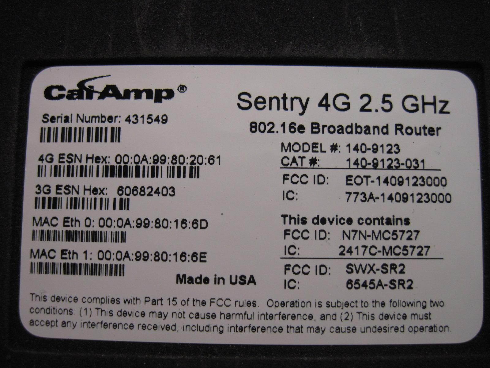
EOT-1409123000
May 15, 20112.5 GHz Wireless Broadband Route
Equipment Class
TNB - Licensed Non-Broadcast Station Transmitter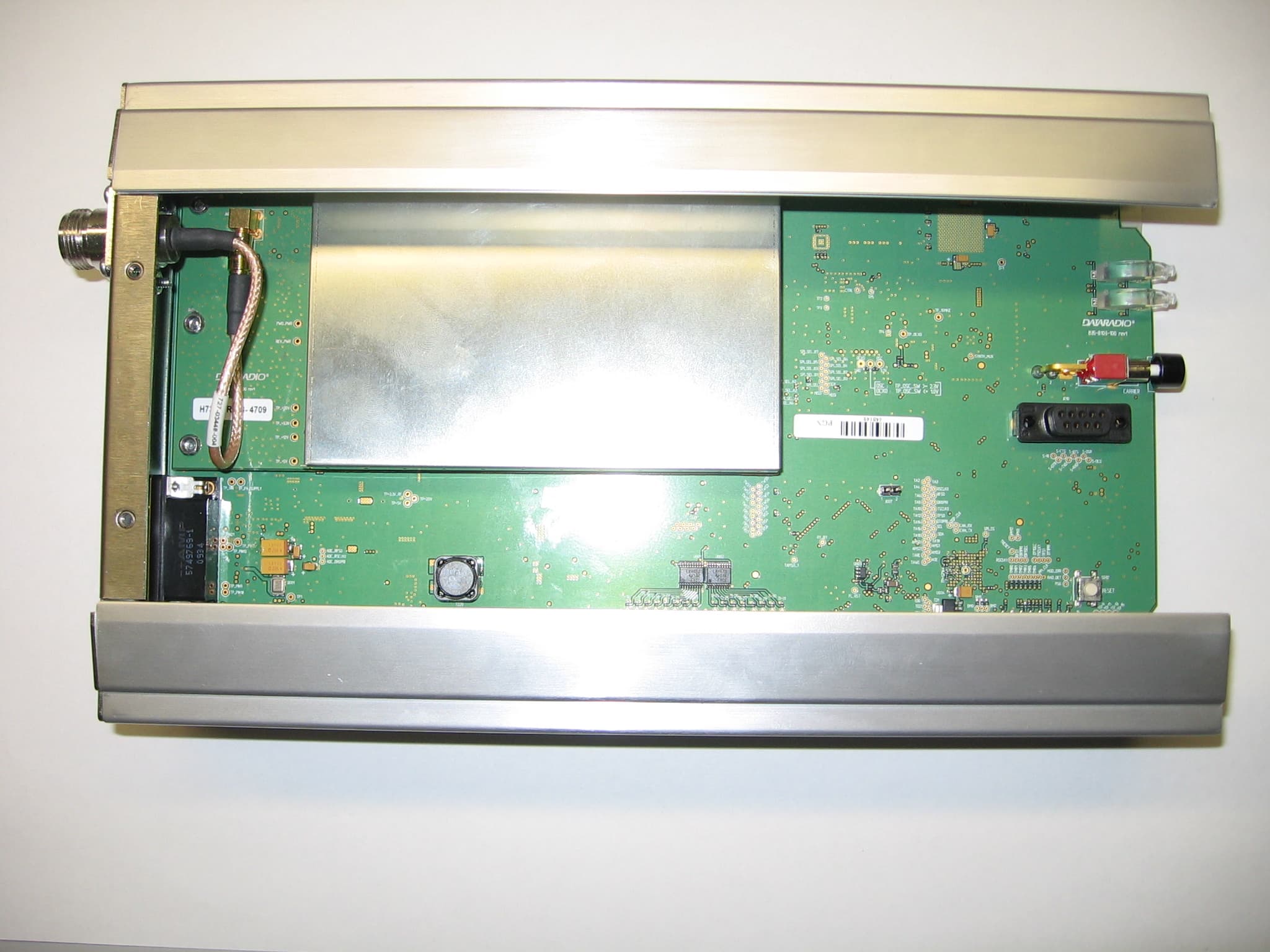
EOTBDP4-EXCT769
Sep 29, 2010700MHz Band SDR Exciter for BDP4 digital base station
Equipment Class
TNB - Licensed Non-Broadcast Station Transmitter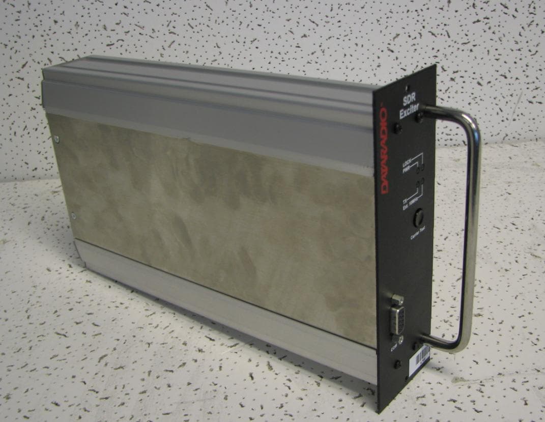
EOTBDP4-EXCT438
Jun 03, 2010UHF HIGH SDR Exciter for BDP4 digital base station
Equipment Class
TNB - Licensed Non-Broadcast Station Transmitter
EOTBDP4-EXCT403
Jun 02, 2010UHF LOW SDR Exciter for BDP4 digital base station
Equipment Class
TNB - Licensed Non-Broadcast Station Transmitter
EOT-1409290100
May 09, 2010900 MHz Broadband Base Station
Equipment Class
DTS - Digital Transmission System