EOTGPD7G3
CALAMP WIRELESS NETWORKS INC.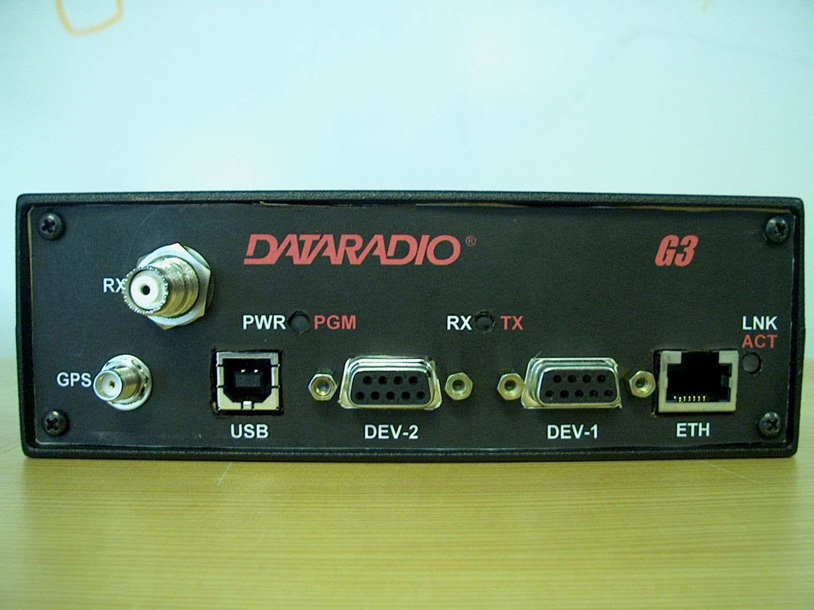
Click to zoom
Application Details
- Equipment Class
- TNB - Licensed Non-Broadcast Station Transmitter
- Date of Grant
- Mar 17, 2003
- Application Purpose
- Original Equipment
- Date of Application
- Feb 04, 2003
- Equipment Note
- G3
- Frequency Range
- 792.00000000 - 803.00000000
- Country
- United States
Documents & Files
Document Text
Text extracted from the exhibit documents filed with the FCC. Open a document above to read the original.
Users Manual
Dataradio G3 Mobile Radiomodem Installation Guide Version 0.01 PRELIMINARY, For Internal Use Only The entire contents of this manual and the Radio Installation Software described in this manual are copyright 2002 by DATARADIO Inc. Copyright DATARADIO Inc. January, 2003 Part no.: 156 90000-508 Table of Contents 1. PRODUCT OVERVIEW ...................................................................................................................................1 1.1 I NTENDED AUDIENCE........................................................................................................................................1 1.2 G ENERAL DESCRIPTION.....................................................................................................................................1 1.2.1 Features ...................................................................................................................................................1 1.2.2 Configuration...........................................................................................................................................1 1.3 F ACTORY TECHNICAL SUPPORT........................................................................................................................1 1.4 P RODUCT WARRANTY.......................................................................................................................................2 1.5 R EPLACEMENT PARTS.......................................................................................................................................2 1.5.1 Factory Repair.........................................................................................................................................2 1.6 U NPACKING.......................................................................................................................................................2 2. INSTALLATION................................................................................................................................................3 2.1 P LANNING THE INSTALLATION..........................................................................................................................3 2.1.1 Overview ..................................................................................................................................................3 2.1.2 Location ...................................................................................................................................................3 2.1.3 Cable Path ...............................................................................................................................................3 2.2 W ARNINGS........................................................................................................................................................3 2.2.1 RF Radiation warning .............................................................................................................................3 2.2.2 Interference with vehicular electronics ...................................................................................................3 2.2.3 Secure mounting ......................................................................................................................................3 2.2.4 Explosive environments ...........................................................................................................................3 2.2.5 Installation in vehicles powered by liquefied gas. ...................................................................................4 2.3 P HYSICAL UNIT.................................................................................................................................................4 2.3.1 Recommended tools and supplies ............................................................................................................4 2.3.2 Physical mounting of G3.........................................................................................................................4 2.4 E LECTRICAL INSTALLATION..............................................................................................................................5 2.4.1 Electrical requirements ...........................................................................................................................5 2.4.2 Routing of power cable ............................................................................................................................5 2.5 A NTENNA..........................................................................................................................................................7 2.5.1 Recommended tools and supplies ............................................................................................................7 2.5.2 Planning ..................................................................................................................................................7 2.5.3 Antenna Installation ................................................................................................................................8 2.6. C OMPLETING THE PHYSICAL INSTALLATION. ................................................................................................8 2.7. C HECKING OUT NORMAL OPERATION............................................................................................................8 3. OPERATING DESCRIPTION .........................................................................................................................9 3.1 F RONT & REAR PANELS....................................................................................................................................9 3.2 DTE PORT INTERFACE....................................................................................................................................10 4. TROUBLE-SHOOTING AND TESTING ........................…
Text truncated - open the document above for the full version.
Cover Letter(s)
FCC ID EOTGPD7 new FCC ID request Applicant Dataradio Inc. Request for Confidentiality for Annex B – Circuit Description Annex E - Schematics The request for confidentiality as per FCC 0.459 (a) refers to the exhibits uploaded as Annexes of the report. These parts contain proprietary details of the internal workings of the product and its protocol, the publication of which could be detrimental to our firm if taken out of context by competitors. For these reasons we request that the above mentioned document be made confidential as per FCC 0.457(d)(2). Best Regards, Norman Pearl VP Engineering Dataradio Inc
External Photos
GPD7-Dataradio G3 Engineering Report Annex F Pictur es set F3- External pag1/3 156-90000-506 Dataradio© FCC submission Annex F Pictures EXTERNAL PHOTOS RULE PART NUMBER: 2.1033 c (11) Front view: GPS antenna, Diversity receiver antenna, the three le d indicators (PWR/PGM, RX/TX an d LNK/ACT) and the ports (USB, two serial, Ethernet) GPD7-Dataradio G3 Engineering Report Annex F Pictur es set F3- External pag2/3 156-90000-506 Dataradio© FCC submission Rear view, Main Tx/Rx antenna connector, power cables GPD7-Dataradio G3 Engineering Report Annex F Pictur es set F3- External pag3/3 156-90000-506 Dataradio© FCC submission
ID Label/Location Info
GPD7- Dataradio G3 Engineering Report Annex F Pictures set F1- Label and placement pag1/1 156-90000-506 Dataradio© FCC submission Annex F Pictures LABEL AND LABEL PLACEMENT RULE PART NUMBER: 2.1033 c (11) The label is located on the left side, toward the rear Tx/Rx connector. On the location photo the label is only a placeholder, the label is going to be as shown separately:
Internal Photos
GPD7- Dataradio G3 Engineering Report Annex F Pictures set F2- Internal pag1/6 156-90000-506 Dataradio© FCC submission Annex F Pictures INTERNAL PHOTOS RULE PART NUMBER: 2.1033 c (11) Top view, lid removed - assembled receiver board GPD7- Dataradio G3 Engineering Report Annex F Pictures set F2- Internal pag2/6 156-90000-506 Dataradio© FCC submission Receivers board, component side GPD7- Dataradio G3 Engineering Report Annex F Pictures set F2- Internal pag3/6 156-90000-506 Dataradio© FCC submission Receivers board, soldering side GPD7- Dataradio G3 Engineering Report Annex F Pictures set F2- Internal pag4/6 156-90000-506 Dataradio© FCC submission Bottom view, lid removed, assembly PA board (toward right) and G3 modem board (toward left) GPD7- Dataradio G3 Engineering Report Annex F Pictures set F2- Internal pag5/6 156-90000-506 Dataradio© FCC submission PA board (toward left) and G3 modem board (toward right) – component side GPD7- Dataradio G3 Engineering Report Annex F Pictures set F2- Internal pag6/6 156-90000-506 Dataradio© FCC submission PA board (toward left) and G3 modem board (toward right) – soldering side
Test Report
Engineering Exhibit in Support of Certification FCC Form 731 for the Mobile Data Platform Transceiver (700 MHz MDP) With the Dataradio G3 Modem FCC ID: EOTGPD7 Trade Name: Dataradio G3 February 6, 2003 EOTGPD7 - Gemini/PD+ Engineering Report - body Page 2 of 7 156-90000-500 Dataradio© FCC submission AFFIDAVIT The technical data included in this report has been accumulated through tests that were performed by me or by engineers under my direction. To the best of my knowledge, all of the data is true and correct. _______________________________________________________ Norman D Pearl Vice-president Engineering, Dataradio Inc. EOTGPD7 - Gemini/PD+ Engineering Report - body Page 3 of 7 156-90000-500 Dataradio© FCC submission Dataradio Inc. Montreal, Canada ENGINEERING STATEMENT OF CONSTANTIN PINTILEI The application consisting of the attached engineering exhibit and associated FCC form 731 has been prepared in support of a request for Certification. Certification is requested for the radio modem Dataradio G3 comprised of the . (DRL) Mobile Data Platform (MDP) 700 MHz Transceiver manufactured by Dataradio COR Ltd with the G3 GCU Modem manufactured by Dataradio Inc. The modem/transceiver will operate in the frequency range 792-803 MHz in Transmit and 762-773 MHz in Receive where 50kHz and more wideband operation is authorized. Dataradio, Canada, will buy the MDP from DRL, Waseca, with the part# 242-607C- MRB (see page 6 for part# description). Dataradio will install the modem and perform final assembly. Along with the modem a GPS receiver option is also available. The MDP Transceiver mated with the Dataradio G3 Modem and GPS receiver will be identified by the Dataradio part number GPD7-6075-1RBGF and marketed under the Model name G3. The Transceiver/Modem/GPS will be identified by the FCC number EOTGPD7. The transceiver operates pursuant to Part(s) 90 of the Rules and Regulations. The MDP Transceiver RF power is continuously variable from 10-31 watts and its nominal power is 30W. EXISTING CONDITIONS The units utilized for these Certification measurements were obtained from prototypes. The transceiver is designed to operate on frequencies ranging from 792.000 MHz to 803.000 MHz where 50kHz and more wideband operation is authorized (792-794MHz under part 27 and 796-803 MHz under part 90). The frequency tolerance of the transceiver is .000125% or 1.25 parts per million. The frequency stability of the transceiver is controlled by a temperature compensated crystal oscillator (TCXO) operating at 17.5 MHz. PROPOSED CONDITIONS It is proposed to accept the request for the Dataradio G3 792-803 MHz Transceiver/Modem/GPS for operation in the band of frequencies previously outlined. The applicant anticipates marketing the device for use in wireless transmission of data. PERFORMANCE MEASUREMENTS All measurements were conducted in accordance with the code 47 CFR Section 2 rev.2-164, Nov 15,2002, Section 90 Subpart R(90.521 to 90.555) rev 90-62 Nov 15, 2002 and Section 27 revised Oct 1, 2001. Equipment performance measurements were made in the engineering laboratory of either Dataradio Inc, Montreal, Canada or Dataradio COR LTD, Waseca, Minnesota, on the FCC certified Open Area Test Site at the Transcrypt International / E.F. Johnson Radio Products located at 299 Johnson Avenue in Waseca, Minnesota. All measurements were made under my direction. The performance measurements were made between Dec 1 st , 2002 and Jan 20, 2003 CONCLUSION Given the results of the measurements contained herein, the applicant requests that Certification be granted for the Dataradio G3, 792-803 MHz wideband Transceiver/Modem/GPS as tested for data communications. 01/28/2003 Constantin Pintilei, Eng R&D Test Engineer, Dataradio Inc. EOTGPD7 - Gemini/PD+ Engineering Report - body Page 4 of 7 156-90000-500 Dataradio© FCC submission TABLE OF CONTENTS AFFIDAVIT .............................................................................................................................................................................................. 2 ENGINEERING STATEMENT................................................................................................................................................................ 3 TABLE OF CONTENTS........................................................................................................................................................................... 4 QUALIFICATIONS OF ENGINEERING PERSONNEL ........................................................................................................................ 5 GENERAL INFORMATION ABOUT THE GRANTEE AND CERTIFICATED EQUIPMENT -2.1043 (b)(2) .................................. 6 OTHER DATA- Rule Part Number: 2.1033 (c).(3),(8),(9),(10),(11),(12),(13),(15),(16), 1.1091, 15.209 .............................................. 7 ANNEXES( -document index): Annex A (-501): Test reports section. A0 - General. MPE calculation (2.1091, 27.52 ) A1- Transmitter Rated Power Output (2.1046, 90.541, 27.50(a)(2) ) A2- Modulation characteristics (2.1047, 90.535 ) A3-Occupied bandwidth (2.1049, 90.543(d), 27.53(d)(4) ) A4 -Spurious Emissons at Antenna Terminals (2.1051,90.543(c) &(e), 27.53(c)(e) ) A5- Field Strength of Spurious Radiation (2.1053,90.543(c), 27.53(c) ) A6- Field Strength of Spurious Radiation (2.1053,90.543(c), 27.53(c) ) Receiver Radiation Limits A7- Frequency Stability vs Variation in Ambient Temperature (2.1055(a), 90.539,27.54) A8- Frequency Stability vs Variation in Supply Voltage (2.1055(d),90.539,27.54) A9- Emission Limitations (ACCP) (90.543 (a),(b), 27.53(d) ) Annex B (-502): Transceiver Theory of Operation, Synthesizer Block Diagram, Transceiver Block Diagram, Modem Theory of Operation, Modem Block Diagram Annex C (-503): Transistor, Diode and IC Functions Annex D (-504): Transmitter Tune Up Procedure Annex E (-505): Schematics E1 – MDP-60xx – transceiver schematics E2 – GCU3 – modem schematics Annex F (-506): Pictur…
Text truncated - open the document above for the full version.
Test Report
GPD7 –Dataradio G3 Engineering Report – Annex A – Part A0 General (reference section) A0 Page 1 of 2 156-90000-501 Dataradio© FCC submission ANNEX A TEST DATA Section Rule Part Number: 2.1033 (c)(14) All applicable test data according to: -Part 2: 2.1046, 2.1047, 2.1049, 2.1051, 2.1053 and 2.1057 -Part 15:15.207, 15.209 -Part 90, Subpart R: 90.521 to 90.555 -Part 27, Subpart C: 25.50 to 27.54 are provided in this section of the Engineering Report, as shown detailed below: part- pages Data Contents FCC parts Laboratory A0-1 General. Data efficiency RF Safety 2.1033 (c)(14) 90.535(a)(c) 2.1091(c),27.52 A1-1 Transmitter Rated Power Output 2.1046, 90.541, 27.50(a)(2) R&D Dataradio Inc A2-1 Modulation characteristics 2.1047, 90.535 R&D Dataradio Inc A3-2 Occupied bandwidth 2.1049, 90.543(d),27.53(d)(4) R&D Dataradio Inc A4-2 Spurious Emissons at Antenna Terminals 2.1051,90.543(c),27.53(d)(3) R&D Dataradio COR A5-3 Field Strength of Spurious Radiation 2.1053,90.543(c),(e),27.53(e) R&D Dataradio COR A6-4 Field Strength of Spurious Radiation (Receiver Radiation Limits ) 2.1053,90.543(c),15.207&209 R&D Dataradio COR A7-2 Frequency Stability vs Variation in Ambient Temperature 2.1055(a), 90.539,27.54 R&D Dataradio Inc A8-1 Frequency Stability vs Variation in Supply Voltage 2.1055(d),90.539,27.54 R&D Dataradio Inc A9- 11 Adjacent Channel Coupled Power 90.543(a),(b),27.53(d) R&D Dataradio Inc 28 Total number of report pages The following reports have been generated for FCC Certification of the Dataradio 792-803 MHz Transceiver/Modem/GPS, part number GPD7-6075-112 00. Unless otherwise noted, all of the measurements were conducted following the procedures set forth in the TIA/EIA-603 standards. Set-up and equipment identification Dataradio Inc Dataradio COR Units under test Prototype MDP 700MHz+G3, Serial: 00005 Units under test Prototype, Serial: 00003 Open Area Test Site (OATS): FCC certified Open Area Test Site at the Transcrypt International / E.F. Johnson Radio Products located at 299 Johnson Avenue in Waseca, Minnesota Modulation and Spectrum Usage Efficiency The unit employs only digital modulation as per 90.535 (a). The unit is designed for a channel size of 50 kHz as per 90.531(c) with a spectrum efficiency of 128kbps/50kHz . This equates to 128*3kbps/50*3kHz=384kbps/150kHz as required by 90.535(c) GPD7 –Dataradio G3 Engineering Report – Annex A – Part A0 General (reference section) A0 Page 2 of 2 156-90000-501 Dataradio© FCC submission The part 90.531(d)(2) states that two or three contiguous wideband (50 kHz) channels may be used in combination as 100 kHz or 150 kHz channels. Rates of 256kbps/100kHz and 384kbps/150 kHz respectively can be achieved running 3 units appropriately programmed RF Safety rule: FCC part 2.1091, part 1.1310 Maximum Standard: FCC part 1.1310 table 1 [B] Frequency range: 300-1500 MHz values: 792-806MHz (max Tx freq) Power Density f/1500 mW/cm2 0.528-0.537 mW/cm2 The exposure should not exceed 0.537 mW/cm2 Estimation Result: Meets maximum standard (0.478mW/cm 2 ) @50%duty cycle Theoretical Estimation of Exposure Fields: as per OET Bulletin 65 section 2 formula (3) page 19 for power density and section 1 formula (2) for time averaging . Calculations Performed By . . date Jan 17, 2003 Constantin Pintilei Note: The calculation will consider the worst case (minimum limit) for RF exposure as follow: f=792 MHz λ=3*10 8 (m/s)/792*10 6 (Hz)=0.378m r=0.5 m - mag-mount antenna and person standing next to the car. r>λ/(2π) =>far field region P T =30W -maximum transmitted power G=0dB - unity gain mag-mount antenna, no cable loses - for worst case. no spatial averaging 50% average Tx duty cycle , half duplex unit Formulas: Time - averaged power density: S t t StS t S avg n i i n i ii avg * 1 1 1 lim η=== ∑ ∑ = = ; Far-field region power density: 2 *4r GP S T π = For an 50% Tx duty cycle 775.4 5.0*4 1*30 *5.0 2 == π W W/m 2 =0.4775mW/cm 2
Test Report
GPD7 – Dataradio G3 Engineering Report – Annex A – Part A1 Transmitted power A1 Page 1 of 1 156-90000-501 Dataradio© FCC submission NAME OF TEST: Transmitter Rated Power Output RULE PART NUMBER: 2.1046 (a), 90.541,27.50(a)(2) UNIT UNDER TEST Prototype unit TEST RESULTS: ≤30W, Meets minimum standard, see data below TEST CONDITIONS: Standard Test Conditions, 25 C TEST EQUIPMENT: Digital Voltmeter, Fluke 77 series II multimeter DC Power Supply , Astron Model VS-20M True RMS clamp multimeter, EXTECH instrument model 380947 IFR COM-120B Spectrum Analyzer, Model HP E4401 PERFORMED BY: DATE: 12/04/02 Constantin Pintilei TEST SET-UP: TEST RESULTS: Frequency (ch 180) (MHz ) DC Voltage at Final (VDC) DC Current into Final (ADC) DC Power into Final (W) RF Power Output (W) 800.025 13.78 5.28 72.76 29.9 800.025 13.79 4.15 57.19 10.1 Power Supply Radio under test IFR COM120B Ant. T/R Pwr Connecto r Clamp Ampmeter Digital Voltmeter
Test Report
GPD7 – Dataradio G3 Engineering Report – Annex A – Part A2 Modulation Source A8 Page 1 of 1 156-90000-501 Dataradio© FCC submission MODULATION SOURCE DESCRIPTION: RULE PART NUMBER: 2.1047, 90.535 The G3+ modem generates digitized multi-level frequency shift keying modulating signal. This digital modulation scheme is produced by the main CPU in conjunction with the DSP processor as follows: The main CPU processes incoming binary data to comply with data layer requirements, and then this binary stream is fed to the DSP processor which runs the functions of applying Forward Error Correction (FEC), interleaving and scrambling in binary and, from it, generates an NRZ for encoding and pulse shaping. The digital processing computes the binary differential and maps the binary stream into a symbol stream. The binary stream is processed as stream of clusters of multiple-bits as required by multiple level FSK modulation type. The number of levels of the digital symbol stream corresponds to the numbers of levels of NFSK modulation. The digital symbol signal has further applied a pulse shaping filter through the DSP. The pulse-shaping filter is in Raised Cosine family and the appropriate equation designs the filter characteristic together with the 3dB cutoff frequency. The equation trim factor, which for RC family is the cosine weight “α”, is set according to the bit rate selected and channel bandwidth as follows: Bit rate levels FSK Symbol rate Pulse shape and modulation type Acronyms/ factor / 3dB cutoff frequency Deviation Occupied Bandwidth 128000 bps 16 32000 bauds Raised Cosine 16 Levels Frequency Shift Keying RC16FSK α=0.4 16000Hz ± 8.3 KHz 27666Hz The pulse-shaped signal has further applied a amplification constant which adjusts the transmitter deviation level and then is fed to the CODEC for digital to analog conversion. The resulting waveshape applied to the FM modulator will then produce a compact RF spectrum such that, when using proper frequency deviation, to fit inside the restrictive limits inherent to the intended channel bandwidth. The same processes but backwards happen to demodulate the modulated symbols into data stream TX Data Test Pattern: The transmit “test data pattern” command produces a 2047 bit pseudo-random pattern. This pattern is generated by the internal software using the polynomial X 11 +X 9 +1 form and a 12-bit shift register. Initial value of the register is 111111111110 (FFE hex). The 2047 bit sequence is repeated thereafter as long is necessary to complete the test duration (55 sec). This pattern is applied to the DSP processor data input for encoding and pulse shaping as described above.
Test Report
GPD7 – Dataradio G3 Engineering Report – Annex A – Part A3 Occupied Bandwidth A3 Page 1 of 2 156-90000-501 Dataradio© FCC submission Transmitter Occupied Bandwidth and Emission Designator Determination RULE PART NUMBER: 2.201, 2.202,2.1049 (h), 90.543(d), 90.27.53(d)(4) Necessary Bandwidth Measurement (90.202.(c)(4)) and Emission Designator This radiomodem uses digital modulation signals, passing through a pulse shaping DSP implemented low-pass filter to an FM transceiver. The equations for the filter are Nyquist-based being driven by the data symbol rates, they are detailed in modulation source description paragraph, in next page. The necessary bandwidth calculation for this type of modulation is not covered by paragraphs (1), (2) or (3) from 2.202(c), the result exceeding by far the real necessary bandwidth obtained through simulations or measurement. Therefore, the approach outlined in (2.202(c)(4)) is applicable in this case. The results of 99% Occupied Bandwidth measurement are: Bit rate Symbol rate Filter equation Deviation (1kHz tone) Occupied Bandwidth Emission designator 128000 bps 32000 bauds Raised Cosine ± 8.3 KHz 27.67kHz 28K0F1D The value of the necessary bandwidth (and implicitly of the emission designator) doesn’t exceed the authorized bandwidth of 50kHz (90.543(d)). Occupied Bandwidth Measurement (90.202(c)(4) The Occupied Bandwidth measurement option of the instrument (8563EC spectrum analyzer from Agilent) calculates and provides the values used above for the emission designator. The percentage setting of the measurement has been set to 99% following the definition of the Occupied Bandwidth “the frequency bandwidth such that, below its lower and above its upper frequency limits, the mean powers radiated are each equal to 0.5 percent of the total mean power radiated by a given emission” (FCC 2.202) The measurement has been performed using the Occupied Bandwidth Measurement Function of 8563EC the resulting value was recorded as Occupied Bandwidth. UNIT UNDER TEST Prototype unit TEST RESULTS: 27.67kHz TEST CONDITIONS: Standard Test Conditions, 25 C TEST EQUIPMENT: IFR COM-120B – communication analyzer used for deviation meter IF bandwidth 300kHz Spectrum Analyzer, Model HP 8563EC PERFORMED BY: DATE: 12/06/02 Constantin Pintilei . The set-up and the plot acquired during the occupied bandwidth are provided next page. GPD7 – Dataradio G3 Engineering Report – Annex A – Part A3 Occupied Bandwidth A3 Page 2 of 2 156-90000-501 Dataradio© FCC submission The measurement set-up is: The plot acquired during the occupied bandwidth . random data generator and transceiver loader (software) unit under test 30 dB attenuator spectrum analyzer Agilent - 8563EC frequency deviation meter IFR-COM 120A (alternating with 8563 EC)
Test Report
GPD7 – DataradioG3 Engineering Report – Annex A – Part A4 Transmitter Harmonic Outputs & Spurs A4 Page 1 of 3 156-90000-501 Dataradio© FCC submission NAME OF TEST: Transmitter Spurious and Harmonic Outputs RULE PART NUMBER: 2.1051,90.543(c),27.53(d)(3) MINIMUM STANDARD: 27.53(d)(3); 90.543(c): 43+10Log 10 (P( Watts)) For 30Watt Ù 58dBc ; For 10 WattÙ 53 dBc TEST RESULTS: Meets minimum standard (see data on the following page) TEST CONDITIONS: Standard Test Conditions, 25 C RF voltage measured at antenna terminals TEST PROCEDURE: TIA/EIA - 603, 2.2.13 TEST EQUIPMENT: Attenuator, BIRD Model / 100-A-MFN-20 / 20 dB / 100 Watt Attenuator, BIRD Model / 50-A-MFN-03 / 3 dB / 50 Watt Digital Voltmeter, Fluke Model 8012A DC Power Source, Model HP6038A Spectrum Analyzer, Model HP8563E Reference Generator, Model HP83732B Power Meter, Model HP 8901B Audio Generator, Model HP8903B PERFORMED BY: Date: Jan 2, 2003 Allen Frederick ATTENUATOR NOTCH FILTER SPECTRUM ANALYZER POWER SUPPLY DIGITAL MULTIMETER POWER METER TRANSCEIVER UNDER TEST REFERENCE GENERATOR AUDIO GENERATOR GPD7 – DataradioG3 Engineering Report – Annex A – Part A4 Transmitter Harmonic Outputs & Spurs A4 Page 2 of 3 156-90000-501 Dataradio© FCC submission NAME OF TEST: Transmitter Spurious and Harmonic Outputs (Continued) MEASUREMENT PROCEDURE: 1. The transmitter carrier output frequency is 800 MHz. The reference oscillator frequency is 17.5000 MHz. 2. After carrier reference was established on spectrum analyzer, the notch filter was adjusted to null the carrier Fc to extend the range of the spectrum analyzer for harmonic measurements. 3. At each spurious frequency, Generator substitution was used to establish the true spurious level. 4. The spectrum was scanned to the 10th harmonic. TEST DATA: See following page. GPD7 – DataradioG3 Engineering Report – Annex A – Part A4 Transmitter Harmonic Outputs & Spurs A4 Page 3 of 3 156-90000-501 Dataradio© FCC submission NAME OF TEST: Transmitter Spurious and Harmonic Outputs (Continued) Power (W): 30 W Min Spec: 57.8 dBc Power (dBm): 44.7 dBm Worse Spur: -77.3 dBc Freq (MHz): 800 MHz Spec An Loss dBm dBc 2 1600 -92.0 22.7 -69.3 -114.1 3 2400 -65.7 23.0 -42.7 -87.5 4 3200 -87.0 29.8 -57.2 -102.0 5 4000 -76.5 38.0 -38.5 -83.3 6 4800 -62.5 30.0 -32.5 -77.3 7 5600 -101.0 56.3 -44.7 -89.5 8 6400 -88.0 46.8 -41.2 -86.0 9 7200 -81.0 33.8 -47.2 -92.0 10 8000 -105.0 62.5 -42.5 -87.3 Power (W): 10 W Min Spec: 53.0 dBc Power (dBm): 40.0 dBm Worse Spur: -82.0 dBc Freq (MHz): 800 MHz Spec An Loss dBm dBc 2 1600 -95.0 22.7 -72.3 -112.3 3 2400 -93.0 23.0 -70.0 -110.0 4 3200 -107.0 29.8 -77.2 -117.2 5 4000 -86.0 38.0 -48.0 -88.0 6 4800 -72.0 30.0 -42.0 -82.0 7 5600 -110.0 56.3 -53.7 -93.7 8 6400 -103.0 46.8 -56.2 -96.2 9 7200 -102.0 33.8 -68.2 -108.2 10 8000 -110.0 62.5 -47.5 -87.5
Test Report
GPD7 – Dataradio G3 Engineering Report – Annex A – Part A5 Field strength of spurious Radiation A5 Page 1 of 5 156-90000-501 Dataradio© FCC submission NAME OF TEST: Field Strength of Spurious Radiation RULE PART NUMBER: 2.1053, 90.543(c)(e), 27.53(e) MINIMUM STANDARD: For 30 Watts: 43+10Log 10 (30) = 58 dBc For 10 Watts: 43+10Log 10 (10) = 53 dBc 27.53(e);90.543(e): in the band 1559—1610 MHz -70 dBW/MHz EIRP for wideband signals, and -80 dBW EIRP for discrete emissions of less than 700 Hz bandwidth UNIT UNDER TEST TEST RESULTS: Meets minimum standard (see data on the following page) TEST CONDITIONS: Standard Test Conditions, 25 C TEST PROCEDURE: TIA/EIA - 603, 2.2.12 TEST EQUIPMENT: Log Spiral Antenna, Model 93491-2 Horn Antenna, Model EMCO 3115 Reference Generator, Model HP83732A Attenuator, BIRD Model / 100-A-MFN-20 / 20 dB / 100 Watt Attenuator, BIRD Model / 50-A-MFN-03 / 3 dB / 50 Watt Spectrum Analyzer, Model HP8563E Power Meter, Model HP 8901B Power Supply, Model HP6038A MEASUREMENT PROCEDURE: Radiated spurious attenuation was measured according to TIA/EIA Standard 603 Section 2.2.12 TEST SET-UP: PERFORMED BY: Date: Jan 9, 2003 Allen Frederick SPECTRUM ANALYZER POWER METER REFERENCE GENERATOR LOAD TEST UNIT REFERENCE ANTENNA RECEIVING ANTENNA 10 ft. GPD7 – Dataradio G3 Engineering Report – Annex A – Part A5 Field strength of spurious Radiation A5 Page 2 of 5 156-90000-501 Dataradio© FCC submission NAME OF TEST: Spurious Radiation Attenuation (Continued) Freqency: 800 MHz Spec = -57.8 dBc Power: 30 Watts Highest Spur = -77.1 dBc 44.8 dBm Spurious Substitution Antenna Circular Spurious Frequency Polarization Spurious Generator Cable Loss Gain Polarization Attenuation (MHz) (Horz/Vert) Level (dBm) (dBm) (dB) (dBd) Correction (dB) dBc 1600 H -90.8 -45.0 7.00 1.20 3.0 -98.6 V -89.8 -45.0 7.00 1.20 3.0 -98.6 2400 H -71.8 -22.7 7.83 1.20 3.0 -77.1 V -76.3 -26.3 7.83 1.20 3.0 -80.7 3200 H -80.3 -25.3 9.50 1.20 3.0 -81.4 V -78.0 -22.7 9.50 1.20 3.0 -78.8 4000 H -94.2 -32.8 11.83 1.20 3.0 -91.2 V -91.7 -29.3 11.83 1.20 3.0 -87.7 4800 H -97.2 -33.7 12.83 1.20 3.0 -93.1 V -93.0 -29.7 12.83 1.20 3.0 -89.1 5600 H -93.7 -26.3 14.00 1.20 3.0 -86…
Text truncated - open the document above for the full version.
Contact Information
Applicant
Russell Cook(Director of Engineer)
[email protected]612-642-2127
Technical Contact
Dataradio IncConstantin Pintilei
[email protected]514-737-0020
200-5500 Royalmount Ave · Mount-Royal, Quebec · Canada
Technical Specifications
| # | Rule Parts | Frequency Range | Power Output | Emission | Tolerance |
|---|---|---|---|---|---|
| 1 | 27,90 | 792 MHz - 803 MHz | 30 W | 28K0F1D | 1.2500000000 ppm |
Other Applications from CALAMP WIRELESS NETWORKS INC.
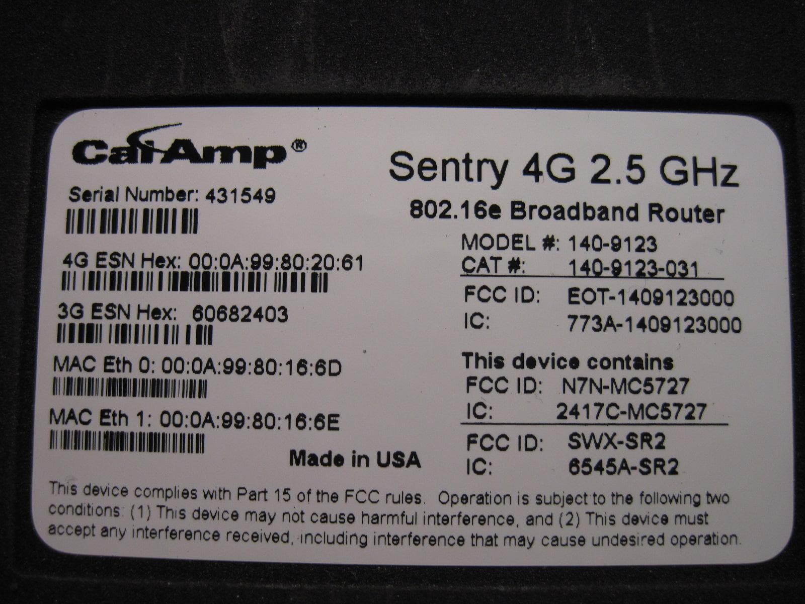
EOT-1409123000
May 15, 20112.5 GHz Wireless Broadband Route
Equipment Class
TNB - Licensed Non-Broadcast Station Transmitter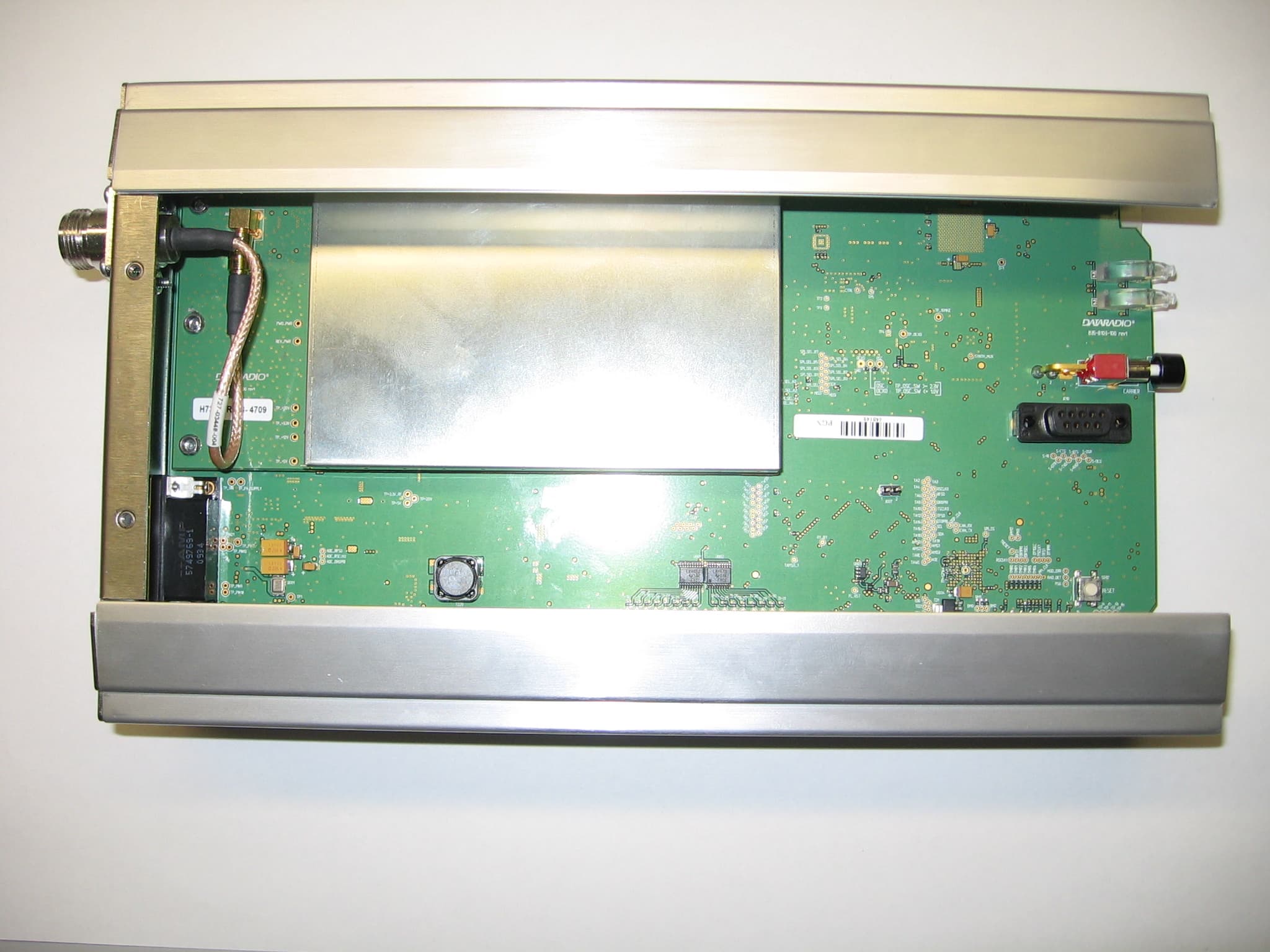
EOTBDP4-EXCT769
Sep 29, 2010700MHz Band SDR Exciter for BDP4 digital base station
Equipment Class
TNB - Licensed Non-Broadcast Station Transmitter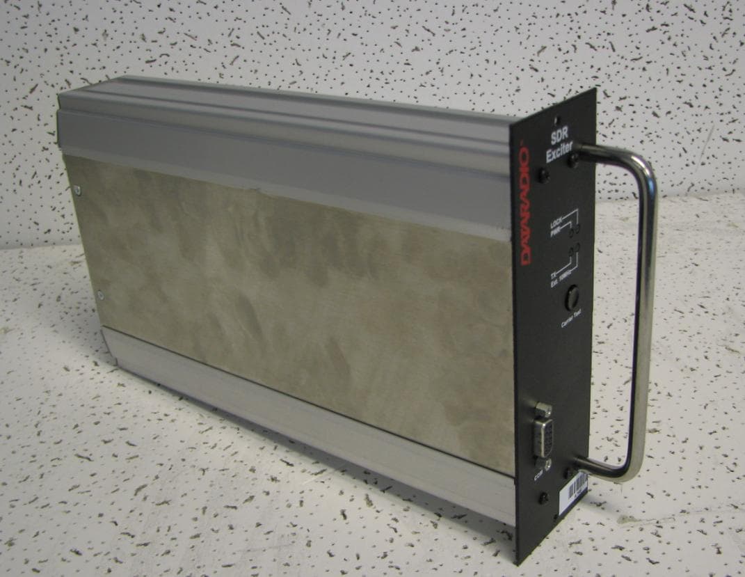
EOTBDP4-EXCT438
Jun 03, 2010UHF HIGH SDR Exciter for BDP4 digital base station
Equipment Class
TNB - Licensed Non-Broadcast Station Transmitter
EOTBDP4-EXCT403
Jun 02, 2010UHF LOW SDR Exciter for BDP4 digital base station
Equipment Class
TNB - Licensed Non-Broadcast Station Transmitter
EOT-1409290100
May 09, 2010900 MHz Broadband Base Station
Equipment Class
DTS - Digital Transmission System