EOTGPDBGemini/PD
CALAMP WIRELESS NETWORKS INC.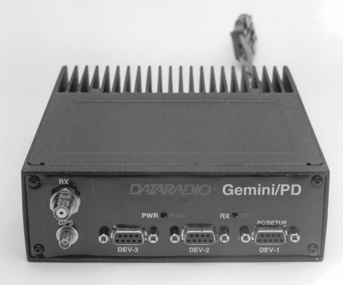
Click to zoom
Application Details
- Equipment Class
- TNB - Licensed Non-Broadcast Station Transmitter
- Date of Grant
- Jun 11, 2000
- Application Purpose
- Original Equipment
- Date of Application
- Nov 21, 1999
- Equipment Note
- Gemini/PD
- Frequency Range
- 806.00000000 - 824.00000000
- Country
- United States
Documents & Files
Document Text
Text extracted from the exhibit documents filed with the FCC. Open a document above to read the original.
Users Manual
Gemini / PD Mobile Radio Modem Service Manual version 0.03 PRELIMINARY The entire contents of this manual and the Radio Service Software described in this manual are copyright 1998 by DATARADIO Inc. Copyright DATARADIO Inc. November 1998 part no.: 120 1020110-003 i Table of Contents 1.PRODUCT OVERVIEW................................................................................................................................... 1 1.1 I NTENDED AUDIENCE....................................................................................................................................... 1 1.2 G ENERAL DESCRIPTION.................................................................................................................................... 1 1.3 C ONFIGURATION............................................................................................................................................... 1 1.4 F ACTORY TECHNICAL SUPPORT........................................................................................................................ 2 1.5 P RODUCT WARRANTY...................................................................................................................................... 2 1.6 R EPLACEMENT PARTS....................................................................................................................................... 2 1.6.1Factory Repair ........................................................................................................................................ 2 2.OPERATION...................................................................................................................................................... 2 2.1 F RONT & REAR PANELS................................................................................................................................... 2 2.1.1LED Indicators........................................................................................................................................ 3 2.2 DTE P ORT INTERFACE..................................................................................................................................... 3 2.2.1RS-232 Interface Signal Levels ............................................................................................................... 3 3.ADJUSTMENTS AND MAINTENANCE ....................................................................................................... 4 3.1 O VERVIEW........................................................................................................................................................ 4 3.1 I NTENDED AUDIENCE....................................................................................................................................... 4 3.2 E QUIPMENT REQUIRED..................................................................................................................................... 4 3.3 M AINTENANCE INTERVALS...............................................................................................................................4 3.4 T ESTS & ADJUSTMENTS................................................................................................................................... 4 3.4.1Preliminary Verification ......................................................................................................................... 4 3.4.2Basic Tests & adjustments....................................................................................................................... 4 3.4.3Tests & adjustments Procedure............................................................................................................... 4 3.4.4Opening the Unit ..................................................................................................................................... 6 3.4.5GPS Diagnostics Procedure.................................................................................................................... 7 4.SPECIFICATIONS ............................................................................................................................................ 8 ii What's New in Version 0.02 GPS Diagnostics procedure History Version 0.1: First preliminary version Version 0.2: • Unit specification revised • Typo correction iii Definitions The following terms are used throughout this document. ItemDefinition DCEData Communications Equipment. This designation defines the direction (input or output) of the various RS-232C interface signals. Modems are always wired as DCE. See also DTE. DTEData Terminal Equipment. This designation defines the direction (input or out- put) of the various RS-232C interface signals. Most user equipment, as well as PCs, are wired as DTE. See also DCE. GCUGemini Control Unit board Gemini/PDHigh specs mobile radio modem. PD = Parallel decode HDXHalf Duplex. A unit which uses separate transmit and receive frequencies, but which may not transmit and receive simultaneously. RS-232Industry–standard interface for low speed data transfer (EIA-RS-232E). RSSRadio Service Software. This software allows configuration and testing of the Gemini/PD. SimplexA unit which uses the same frequency for transmit and receive. 120 20110-003 PRELIMINARYGemini/PD Technical Manual 1 1. PRODUCT OVERVIEW This document provides the information required for the operation and maintenance of the DATARADIO Gemini/PD mobile radio- modem. 1.1 Intended Audience This document is designed for use by engi- neering design, installation, and mainte- nance personnel. 1.2 General Description Gemini/PD is a mobile radio-modem aimed at the public safety and public utility markets to meet demand for high speed and high throughput. It integrates all the necessary hardware for data-only vehicular installations up to but not including the laptop PC and its application software. Example of applications are: 1. Database inquiry systems. Small number of brief …
Text truncated - open the document above for the full version.
Users Manual
Gemini PD Mobile Radiomodem Installation Guide Version 1.10 The entire contents of this manual and the Radio Installation Software described in this manual are copyright 2000 by DATARADIO Inc. Copyright DATARADIO Inc. March 2000 Part no.: 120 20110-110 Table of Contents 1.PRODUCT OVERVIEW................................................................................................................................... 1 1.1 I NTENDED A UDIENCE ....................................................................................................................................... 1 1.2 G ENERAL D ESCRIPTION .................................................................................................................................... 1 1.2.1Features: ................................................................................................................................................. 1 1.2.2Configuration .......................................................................................................................................... 1 1.3 F ACTORY T ECHNICAL S UPPORT ........................................................................................................................ 2 1.4 P RODUCT W ARRANTY ...................................................................................................................................... 2 1.5 R EPLACEMENT P ARTS ....................................................................................................................................... 2 1.5.1Factory Repair ........................................................................................................................................ 2 1.6 U NPACKING ...................................................................................................................................................... 2 2.INSTALLATION ............................................................................................................................................... 3 2.1 P LANNING THE I NSTALLATION .......................................................................................................................... 3 2.1.1Overview ................................................................................................................................................. 3 2.1.2Location .................................................................................................................................................. 3 2.1.3Cable Path............................................................................................................................................... 3 2.2 W ARNINGS ........................................................................................................................................................ 3 2.2.1RF Radiation warning............................................................................................................................. 3 2.2.2Interference with vehicular electronics ................................................................................................... 3 2.2.3Secure mounting...................................................................................................................................... 4 2.2.4Explosive environments........................................................................................................................... 4 2.2.5Installation in vehicles powered by liquefied gas. .................................................................................. 4 2.3 P HYSICAL U NIT ................................................................................................................................................. 4 2.3.1Recommended tools and supplies............................................................................................................ 4 2.3.2Physical mounting of Gemini PD ............................................................................................................... 4 2.4 E LECTRICAL INSTALLATION .............................................................................................................................. 5 2.4.1Electrical requirements ........................................................................................................................... 5 2.4.2Routing of power cable ........................................................................................................................... 5 2.5 A NTENNA ......................................................................................................................................................... 7 2.5.1Recommended tools and supplies............................................................................................................ 7 2.5.2Planning .................................................................................................................................................. 7 2.5.3Antenna Installation ................................................................................................................................ 8 2.6 C OMPLETING THE PHYSICAL I NSTALLATION ...................................................................................................... 8 2.7 C HECKING OUT N ORMAL OPERATION ................................................................................................................ 8 3.OPERATING DESCRIPTION ......................................................................................................................... 9 3.1 F RONT & R EAR P ANELS ................................................................................................................................... 9 3.2 DTE P ORT I NTERFACE ................................................................................................................................... 10 3.2.1RS-232 Interface Signal Levels ................................…
Text truncated - open the document above for the full version.
Users Manual
120 20111-100 preliminary7Gemini/PD Installation Guide 2.5 Antenna To meet the FCC’s RF Exposure Guidelines, the main transmitter antenna should: - be installed to ensure a 7.9 in/20cm minimum distance between the body of the user or nearby persons and the antenna. -have the antenna gain less cable loss which does not exceed 2.7dBi. 2.5.1 Recommended tools and supplies • circle cutter • hole saw or • socket punch for antenna • Mini-UHF Crimp tool 2.5.2 Planning Ge mini PD commonly uses three separate antennas: • Main transceiver – constraints are MPE limits and omni-directional factors • Auxiliary receiver – constraints are diversity spacing and omni-directional requirements • GPS – constraints are TX spacing and clear sky view. For ground-plane dependent antennas – the center of metal surface is preferable for best omni-directional pattern. For ground-plane independent antennas – installation may be close to the edges of the surface. Follow spacing for TX antenna. Install the antennas in one of the following positions: - Most preferred for all antennas: centerline of roof. For transmitter antenna, it is the ONLY acceptable position. - Less preferred for receiver antenna: trunk lid, providing distance to transmitting antenna is respected whether lid is opened or closed. - Much less preferred, but permissible for receiver antenna: left or right rear fenders, just in back of rear window - Least preferred, but permissible for receiver antenna: left or right front fenders, ahead of windshield Note: Proximity to other vehicle-mounted antennas may cause mutual interference especially at higher frequencies. The auxiliary receiver antenna must be installed at least 5/8 λ distant from the transceiver antenna. The GPS antenna placement requires a fairly unobstructed view of the sky. It must also be at least two feet distant from the transceiver antenna but it may be close to the auxiliary RX antenna. For the optimum antenna spacing at the frequency you are using, consult system engineering. 2.5.3 Antenna Installation 1. Route good quality 50-ohm coaxial cables (e.g. RG-223) from each of the selected antenna positions to the position where the Gemini PD unit is mou nted. 2. Terminate the end at each of the antenna positions with the appropriate connector for the antenna used and make the connection. 3. At the Ge mi ni PD position, cut the three cables to length and terminate with the appropriate plug. For the transceiver and the auxiliary cables, use a Mini-UHF crimp plug using an appropriate crimping tool. For the GPS, use a SMA connector. 4. Positively identify the transceiver mini-UHF plug and connect to the left rear of Ge mini PD . 5. Positively identify the auxiliary receiver mini-UHF plug and connect to the front left of Gemini PD to the RX position. 6. Connect the SMA connector to the GPS position below the auxiliary connector position. 7. Do not skip this last step, trust us; it is an important one. To complete the installation, tie-wrap together the auxiliary and the GPS antenna cables at a point about two inches in 120 20111-100 preliminary8Gemini/PD Installation Guide front of the unit. It will be much easier hereafter to correctly identify which mini- UHF pl ug goes where. You DO NOT want to cross the auxiliary plug with the transceiver plug. 2.6. Completing the physical Installation. To complete the physical installation and prior to testing Gemini PD : • Connect DC Power cable’s connector to Gemini PD ’s until you hear a click as the two parts snap together. • Re-check that all other connections are secure (antennas, PC, etc.) • Switch vehicle ignition ON. You are now ready to check for normal operation and to run the Radio Installation Software (RIS) program for testing or trouble-shooting. 2.7. Checking out Normal operation Check that the vehicle ignition is ON. 1- Check for proper operation of the Gemini PD ’s LEDs as per Table 1 in section 3.1 2- Using the RIS program (described in section 4) and an in-line wattmeter, check forward & reverse power to confirm main antenna installation. 3- Using the RIS, check the RF link with a base station that can be heard by using the RIS “Ping” feature. See paragraph 4.4.4.4 or If user application and its base station are available, test the installation by goi ng t hrou gh a nor mal sequence of transmitting and receiving messages.
External Photos
GPDB-Gemini/PD Annex C Page 1 of 3 156-90004-103Dataradio©FCC submission Section 2- External Photographs PHOTOGRAPHS: RULE PART NUMBER:2.1033 c (12) GPDB-Gemini/PD Annex C Page 2 of 3 156-90004-103 Dataradio© FCC submission GPDB-Gemini/PD Annex C Page 3 of 3 156-90004-103Dataradio©FCC submission
ID Label/Location Info
Section 1 - Label and Location Info FCC LABEL: RULE PART NUMBER: 2.1033 c (11) Location Info: Left side close to rear left corner.
Internal Photos
GPDB-Gemini/PD Annex C Page 1 of 6 156-90004-103Dataradio©FCC submission Section 3- Internal photographs GPDB-Gemini/PD Annex C Page 2 of 6 156-90004-103Dataradio©FCC submission GPDB-Gemini/PD Annex C Page 3 of 6 156-90004-103Dataradio©FCC submission GPDB-Gemini/PD Annex C Page 4 of 6 156-90004-103Dataradio©FCC submission GPDB-Gemini/PD Annex C Page 5 of 6 156-90004-103Dataradio©FCC submission GPDB-Gemini/PD Annex C Page 6 of 6 156-90004-103Dataradio©FCC submission
Operational Description
GPDB-Gemini/PD Annex A Page 1 of 14 156-90004-101Dataradio©FCC submission DESCRIPTION OF CIRCUITRY RULE PART NUMBER:2.1033 (c)(10) MOBILE DATA PRODUCT POWER AMPLIFIER (PA) CIRCUIT BOARD CONNECTIONS Power and ignition sense are supplied to the radio through J650. Since the power is connected directly to the vehicle battery, the ignition sense line tells the radio when the vehicle ignition is on. The PA board connects to the RF board via J600 (a 10-pin socket). This connector supplies power to the RF board through F600 and provides control over the PA board. CR600, a transorb, prevents negative voltages and extremely high positive voltages from damaging the radio by conducting and blowing the 12A in-line fuse. The main antenna is connected to the PA board through J630, a mini-UHF connector. The transmitter output and main receiver input are provided through this 50 ohm connector. The main receiver signal is passed to the RF board through J620, a 50 ohm through-chassis connector. The transmit drive input comes from the RF board through J610, another 50 ohm through-chassis connector. PA TEMPERATURE SENSE One control signal provided to the RF board microprocessor is temperature sense. A thermistor, RT690, is placed next to the final amplifier on the PA board and its resistance changes with the final amplifier temperature. The thermistor is biased by R405 on the RF board providing a voltage that varies linearly with temperature from 15°C to 125°C, the normal temperature range of the PA during use. If the final amplifier temperature exceeds a preset threshold, the microprocessor will fold back the power to prevent thermal destruction of the final. PA FORWARD POWER SENSE The final amplifier output passes through a directional coupler that samples some of the transmit power and rectifies it through CR690 with C681 providing filtering of the RF content. Resistors R672 and R674 drop the voltage down to a suitable level for the microprocessor. The power sense voltage is proportional to the square root of the output power. PRE-TRANSMIT ENABLE The pre-transmit enable signal from the RF board prepares the PA board for transmit. The antenna switch is configured for transmit by turning on CR670 and CR680. POWER CONTROL AND DRIVE BUFFER The power set voltage from the RF board is applied to the non-inverting input of U600A. The PA forward power sense voltage is fed into the inverting input of U600A through CR640, R618, and R616. The output of U600A is fed into a high current amplifier consisting of Q630, Q620, R606, R602, and R604. This amplifier has a voltage gain of approximately two. The output of the high current amplifier provides bias and collector current for Q660, the drive buffer. When the power set voltage is greater than the forward power voltage, U660A turns the high current amplifier on harder increasing the bias to Q660, and provides more drive level. When the forward power voltage is greater than the power set voltage, U660A cuts the high current amplifier level down and decreases the bias to Q660 which reduces the drive level. The input to Q660 is from the PA buffer on the RF board. C623, C624, and L600 provide the input match with feedback from C627 and R642 for stability. The output of Q660 goes to the pre-driver Q670. C633, and C634 provide the inter-stage match. PRE-DRIVER Transistor Q670 is a vertical MOSFET that provides pre-drive level for the driver stage. The output of this stage goes to Q680. C645, C646, L620 and L630 provide the inter-stage match. GPDB-Gemini/PD Annex A Page 2 of 14 156-90004-101Dataradio©FCC submission DRIVER Transistor Q680 is a vertical MOSFET that provides drive level to the final amplifier, Q690. The inter-stage match consists of C648, C649, C656, L640, C659, C660, L650, C657 and C658. FINAL Transistor Q690 is a high power bipolar transistor that is the final amplifier. The output of this stage is matched to 50 ohms using C664, C665, C668, L660, C669, and C670. ANTENNA SWITCH In receive, CR670 and CR680 are biased off and the main receive signal passes from J630 through the low pass filter and forward power detector, C671, L670, C673, C674, and C671) to the RF board main receive input (P200). In transmit, CR670 and CR680 are biased on which shorts the transmit path to the forward power detector and the receive path to ground. When the receive path is grounded, a high impedance is provided from a discrete quarter- wave section formed by C671, L670, and C672 to the transmit path which provides rejection between the transmitter and the receiver. LOW PASS FILTER The transmit signal passes through a 7-pole low pass filter to the antenna to reduce the harmonic content of the final amplifier. The low pass filter consists of C676, C677, C678, and C679. R666 bleeds static charge from the antenna to protect the active devices in the power amplifier. RADIO FREQUENCY (RF) CIRCUIT BOARD CONNECTIONS The RF board connects to the PA board via P600 (a 10-pin header). This connector supplies power to the RF board and provides control over the PA board. The user or modem interface is provided by J400 (a 2 x 12-pin socket). This connector supplies power to the modem or user interface through F401 and provides control over the RF deck. A secondary interface is provided by J450 (a 12-pin male socket) for programming the internal flash or servicing the RF deck while the modem is connected. The main receiver input comes from the PA board through J200 (a 50-ohm through-chassis connector). The transmitter driver output goes to the PA board through J500, another 50 ohm through-chassis connector. The diversity receiver input comes from J300 (a panel mount mini-UHF connector), which is connected through a length of coax to the RF board. MICROCONTROLLER The microcontroller is comprised of microprocessor U420, Serial Communications Interface (SCI) switch Q410 and U410, Serial Peripheral Interface (SPI) switch U430, and Pulse Width Modulation (PWM) filter U450. Y420 sets the microprocessor…
Text truncated - open the document above for the full version.
Parts List/Tune Up Info
GPDB-Gemini/PD Annex E pag1/4 156-90004-104Dataradio©FCC submission Annex E Active Parts List TRANSISTOR, DIODE, AND IC FUNCTIONS RULE PART NUMBER:2.1033 c (10) MDP TRANSCEIVER VCO Active Parts: Ref DesDRLPN CR904623-5005-022BB535 CR914623-5005-022BB535 CR930623-1504-0354035 Q950676-0003-636NE85633 Q960676-0003-636NE85633 Q970676-0003-636NE85633 Q980676-0003-636NE85633 Power Amplifier Active Parts: Ref DesDRLPN CR600623-2906-001MR2535L CR610623-5005-022BB535 CR620623-2016-519BZX84C CR630623-5005-022BB535 CR640623-5005-022BB535 CR650623-5005-022BB535 CR660623-5005-022BB535 CR670623-1504-032MA47059 CR680623-1504-032MA47059 CR690623-1504-016MMBD701LT1 Q600676-0013-032MUN5114T1 Q610676-0003-6582N3904 Q620676-0002-603MJD42C Q630676-0003-6582N3904 Q640676-0013-046MUN5213T1 Q645676-0003-658MMBT3904 Q650676-0003-658MMBT3904 Q660676-0004-098MRF8372, MS1625 Q670676-0006-452D2229UK Q680676-0006-152D2294UK Q690676-0004-817MRF847, 25C4624, SD1414, MS1455 U600644-2019-017MC33172D Radio Frequency Board Active Parts: Ref DesDRLPN CR30623-2016-519BZX84C CR70623-1504-023MBAV99 CR72623-1504-023MBAV99 CR78623-2016-519BZX84C CR139623-5005-022BB535 CR140623-5005-023MMBV609 CR207623-1504-001MMBV3401 CR210623-1504-0354035 GPDB-Gemini/PD Annex E pag2/4 156-90004-104Dataradio©FCC submission Ref DesDRLPN CR215623-1504-0354035 CR220623-1504-002MMBD6050 CR230623-1504-0354035 CR235623-1504-0354035 CR307623-1504-001MMBV3401 CR310623-1504-0354035 CR315623-1504-0354035 CR320623-1504-002MMBD6050 CR330623-1504-0354035 CR335623-1504-0354035 CR453623-2016-519BZX84C CR456623-2016-519BZX84C CR457623-2016-519BZX84C CR485623-2016-519BZX84C CR486623-2016-519BZX84C CR488623-2016-519BZX84C CR805623-5005-022BB535 Q10676-0013-046MUN5213T1 Q11676-0013-701MSD1819A Q12676-0013-701MSD1819A Q13676-0013-701MSD1819A Q20676-0013-032MUN5114T1 Q21676-0013-046MUN5213T1 Q30676-0013-032MUN5114T1 Q31676-0013-701MSD1819A Q40676-0002-603MJD42C Q41676-0003-6582N3904 Q50676-0003-612MMBT4403 Q51676-0003-612MMBT4403 Q52676-0003-6582N3904 Q70676-0013-700MSB1218A Q71676-0013-700MSB1218A Q72676-0013-700MSB1218A Q73676-0013-701MSD1819A Q74676-0013-701MSD1819A Q90676-0003-612MMBT4403 Q91676-0013-046MUN5213T1 Q92676-0003-612MMBT4403 Q93676-0013-046MUN5213T1 Q94676-0003-612MMBT4403 Q95676-0013-046MUN5213T1 Q110676-0013-700MSB1218A Q111676-0003-618MRF9411 Q139676-0013-701MSD1819A Q140676-0003-634MMBT918 Q141676-0003-634MMBT918 Q220676-0013-700MSB1218A Q221676-0003-618MRF9411 Q250676-0003-634MMBT918 Q260676-0013-700MSB1218A Q261676-0003-618MRF9411 GPDB-Gemini/PD Annex E pag3/4 156-90004-104Dataradio©FCC submission Ref DesDRLPN Q270676-0003-634MMBT918 Q320676-0013-700MSB1218A Q321676-0003-618MRF9411 Q350676-0003-634MMBT918 Q360676-0013-700MSB1218A Q361676-0003-618MRF9411 Q370676-0003-634MMBT918 Q410676-0013-046MUN5213T1 Q420676-0013-046MUN5213T1 Q422676-0013-700MSB1218A Q424676-0013-046MUN5213T1 Q426676-0013-700MSB1218A Q510676-0013-700MSB1218A Q520676-0003-618MRF9411 Q550676-0003-640MSA2111 Q805676-0013-701MSD1819A Q820676-0013-032MUN5114T1 Q821676-0013-046MUN5213T1 Q823676-0013-032MUN5114T1 Q824676-0013-046MUN5213T1 U10644-2003-067LP2951 U20644-2003-074544-2003-074 U40644-2019-017MC33172D U80644-3016-051MC14051B U110644-3016-053MC14053B U120644-2019-017MC33172D U250644-0007-019ADE 12MH U260644-2002-037SA676DK U350644-0007-019ADE 12MH U360644-2002-037SA676DK U410644-3766-125MC74HC125 U420644-5008-060644-5008-060 U430644-3016-053MC14053B U440644-2032-007LM50 U450644-2019-017MC33172D U850644-3954-027SA7025DK U880644-2019-017MC33172D U890644-0004-212AD8403 Y420621-0004-916RO49PB38 Y890618-7009-521518-7009-521 TVO231A-F1-1.5-17.5 GPDB-Gemini/PD Annex E pag4/4 156-90004-104Dataradio©FCC submission TRANSISTOR, DIODE, AND IC FUNCTIONS (continued) RULE PART NUMBER:2.1033 c (10) GEMINI MODEM Reference designatorFunctionType D1Diode,Dual Switching Sot-23BAV70LT1 D2Diode,Schotty Rectifier 1a 30vMBRS130LT3 D3Diode,Dual Switching Sot-23BAV70LT1 D4Diode,Schotty Rectifier 1a 30vMBRS130LT3 D5Diode,Dual Switching Sot-23BAV70LT1 DS1Led,3mm,Bicolor, 4 Stack591-3001-1XX DS2Led,3mm,Bicolor, 4 Stack591-3001-1XX U1Flash EEPROM Tsop 32 Pin 4 Megabit (Tsop-40)AT29C040A-10TI U2RAM,CMOS,32K X 8, -40/85, SOP-28TC55257DFL-85L U3Micropower Low Dropout Regulator With ShutdownLT1129IST-3.3 U4Dual D Type Flip-Flop So-1474HC74AD U55v Supervisory Circuits IC S0-8ADM705AR/ MAX705ESA U6MICROPROCESSOR 10 Mhz QFP-100Z84C1510FEC U71.5a,500khz Stepdown Switching Regulat(S0-8)LT1375IS8-5 U8Octal Bidirectional Transceiver Sol-2074LCX245 U9Ic 0ctal3-St Sol-20MC74LCX244DW U10Quad-Op Amp So-14TLC2274I U11Stereo Codec Ssop-24PCM3002E U12ADC 4 Channel, Tssop-16AD7811YRU U13Digitial Signal ProcessorXC56303PV80 U14Micropower Low Dropout Regulator With ShutdownLT1129IST-3.3 U154 Drivers/4 Receivers Rs232 (Sol-24)LT1134AISW U16MICROPROCESSOR 10 Mhz QFP-100Z84C1510FEC U174 Drivers/4 Receivers Rs232 (Sol-24)LT1134AISW U18Hex Inverter Cmos(So-14)74HCT04AD U19Quad 2-Input Or Gate (S0-14)MC74VHC32AD U20Hex Inverter (So-14)74VHC04 U21MICROPROCESSOR 10 Mhz QFP-100Z84C1510FEC U224 Drivers/4 Receivers Rs232 (Sol-24)LT1134AISW X1OSCILLATOR H-CMOS SMD 5V 19.6608mhzF4101R X2OSCILLATOR 3.3V SMD 3.3V 12.288mhzF4100R G-8GSM Receiver OEM board Ashtech (Orbitstar)GPS G-8 OEM
Parts List/Tune Up Info
GPDB-Gemini/PD Annex Fpag1/1 156-90004-105Dataradio©FCC submission Annex F TRANSMITTER TUNE UP PROCEDURE RULE PART NUMBER:2.1033 c (9) The output power is controlled by a digital potentiometer which controls the supply voltage to the 250mW buffer/amp. The MDP Transceiver has a tuning procedure built into the software. The following instructions summarize the procedure for tuning the output power. 1. Connect the transceiver to be aligned to a DC power source capable of supplying 10 amps. Connect the output of the transceiver through a watt meter capable of measuring 50 Watts (10W for low power unit) and into a 50 ohm dummy load. 2. From the Utilities menu of the MDP 6000 Programmer software select Tune Radio. This brings up a box listings all possible tune-up parameters. Click in the box next to Power Out Adjust. 3. The transmitter keys up at the low end of the band and prompts the user to use the page-up and page- down keys to set the power to 40 Watts (10W for low power unit). The page-up, page-down keys vary the DAC value of the digital potentiometer. When complete the user clicks on OK, the DAC value is automatically stored. The software loads the next frequency to be set. 4. This process is repeated at four points across the band. Once the DAC value is determined for these four frequencies the processor interpolates the DAC value for frequencies in between the calibrated frequencies. This ensures equal power output across the entire RF band from 403-512MHz. Deviation is controlled by a dig…
Text truncated - open the document above for the full version.
Contact Information
Applicant
Russell Cook(Director of Engineer)
[email protected]612-642-2127
Technical Contact
Dataradio Inc.Constantin Pintilei
[email protected]514-737-0020
suite 200 · Mount-Royal, Quebec · Canada
Test Firm
E. F. Johnson Co.John Oblak
Technical Specifications
| # | Rule Parts | Frequency Range | Power Output | Emission | Tolerance |
|---|---|---|---|---|---|
| 3 | 9 | 806 MHz - 824 MHz | 40 W | 15K0F1D | 1.5 ppm |
Other Applications from CALAMP WIRELESS NETWORKS INC.
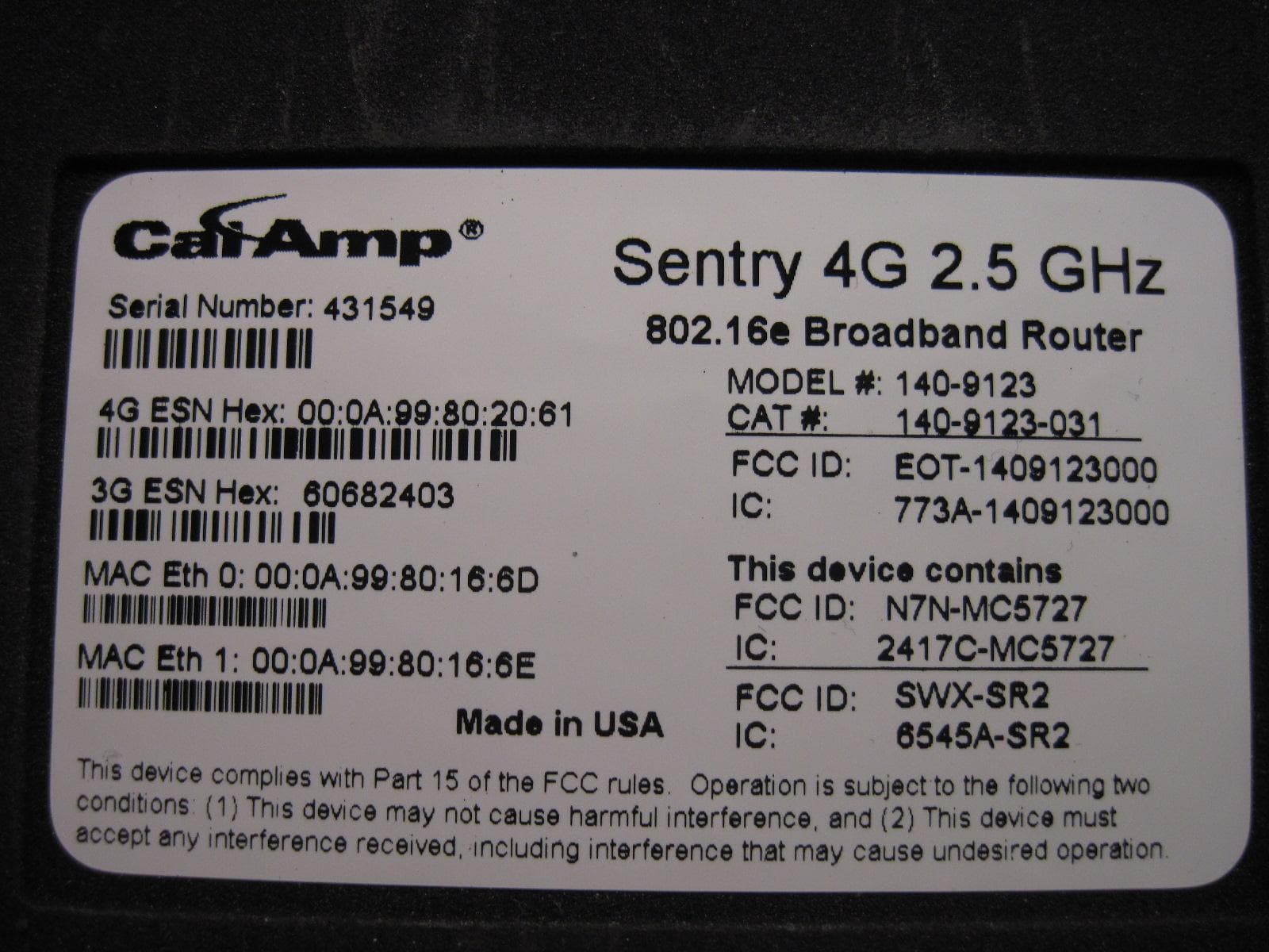
EOT-1409123000
May 15, 20112.5 GHz Wireless Broadband Route
Equipment Class
TNB - Licensed Non-Broadcast Station Transmitter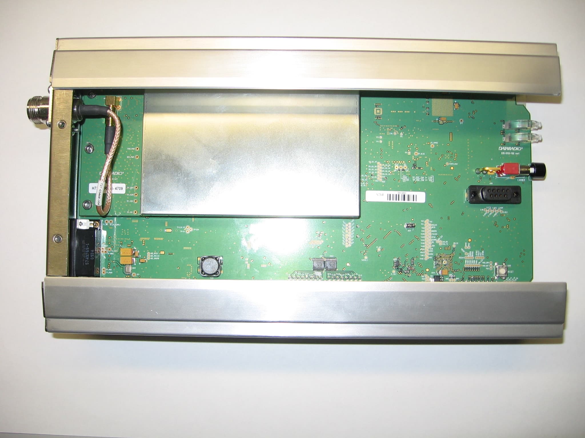
EOTBDP4-EXCT769
Sep 29, 2010700MHz Band SDR Exciter for BDP4 digital base station
Equipment Class
TNB - Licensed Non-Broadcast Station Transmitter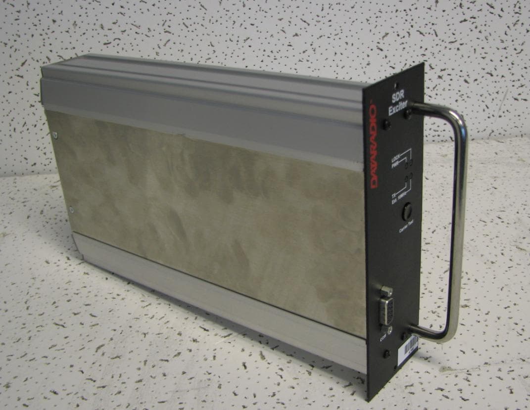
EOTBDP4-EXCT438
Jun 03, 2010UHF HIGH SDR Exciter for BDP4 digital base station
Equipment Class
TNB - Licensed Non-Broadcast Station Transmitter
EOTBDP4-EXCT403
Jun 02, 2010UHF LOW SDR Exciter for BDP4 digital base station
Equipment Class
TNB - Licensed Non-Broadcast Station Transmitter
EOT-1409290100
May 09, 2010900 MHz Broadband Base Station
Equipment Class
DTS - Digital Transmission System