EPK10305350MHz Gas Fireplace Remote Transmitter
Acumen Technologies Ltd
Click to zoom
Application Details
- Equipment Class
- DSC - Part 15 Security/Remote Control Transmitter
- Date of Grant
- Jun 02, 2005
- Application Purpose
- Original Equipment
- Date of Application
- Jun 02, 2005
- Equipment Note
- 350MHz Gas Fireplace Remote Transmitter
- Frequency Range
- 350.00000000 - 350.00000000
- Company
- Acumen Technologies Ltd
- Country
- China
Documents & Files
Document Text
Text extracted from the exhibit documents filed with the FCC. Open a document above to read the original.
Users Manual
Acumen Wall Mount WMT103 Fireplace Remote Control Installation and Operation Instructions: The Acumen Wall Mount WMT103 Remote Control is designed for use with decorative gas fireplace and wall heaters using SIT 825 Nova gas valve. The Wall Mount WMT103 Transmitter is a six-button transmitter, which turn the gas on/off or as a thermostat. The display of the transmitter shows the clock, current room temperature, target temperature, timer setting, on/off status and low battery indicator. Installation Precautions: The Wall Mount WMT103 Remote Control is tested safe when installed in accordance with this installation manual. It is your responsibility to read all instruction before starting installation and to follow these instructions carefully during installation. The Wall Mount WMT 103 Remote Control MUST be installed by a qualified service technician. The Wall Mount WMT 103 Remote Control is carefully engineered and MUST be installed only as specified. If you modify it or any of its components, you may possibly cause a fire hazard. FCC Requirements WARNING: Changes or modifications to this unit not expressly approved by the party responsible for compliance could void the user’s authority to operate the equipment. NOTE: This equipment has been tested and found to comply with the limits for a Class B digital device, pursuant to Part 15 to the FCC Rules. These limits are designed to provide reasonable protection against harmful interference in a residential installation. This equipment generates, uses, and can radiate radio frequency energy and, if not installed and used in accordance with the instructions, may cause harmful interference to radio communications. However, there is no guarantee that interference will not occur in a particular installation. If this equipment does cause harmful interference to radio or television reception, which can be determined by turning the equipment off and on, the user is encouraged to try to correct the interference by one or more of the following measures: – Reorient or relocate the receiver antenna. – Increase the separation between the equipment and receiver. – Connect the equipment into an outlet on a circuit different from that to which the receiver is connected. – Consult the dealer or an experienced radio TV technician for help. Canadian Equipment Requirements This digital apparatus does not exceed the (class A/Class B)* limits for radio noise emissions from digital apparatus set out in the Radio Interference Regulations of the Canadian Department of Communications. Le present appareil numerique n’emet pas de bruits radioelectriques depassant les limites applicables aux appareils numeriques (de la class A/de la class B)* prescrites dans le Reglement sur le brouillage radioelectrique edicte par le ministere des Communications du Canada. This device complies with RSS-210 of Industry Canada. Operation is subject to the following two conditions : (1) this device may not cause interference, and (2) this device must accept any interference, including interference that may cause undesired operation of the device. All wiring should be done by a qualified electrician and shall be in compliance with local codes and with the National Electirc Code ANSI/NFPA No. 70-current (In the United States), or with the current CSA C22.1 Canadian Electirc Code (in Canada). 1.0 Installation Instruction 1.1 Installing the Receiver WARNING: TURN ELECTRICAL POWER OFF AT THE CIRCUIT BEAKER BEFORE BEGINNING THIS INSTALLATION. 1. Connect the electrical service wires to the junction box of the fireplace. 2. Place the receiver onto the base pan of the fireplace. 3. Connect the wires labeled “ Main Valve” to the Millivolt generator and Millivolt valve (see Fig.1) or the Emergency Switch (Fig.2). Switch the Emergency Switch to OFF position if it is installed. Use the Emergency Switch only during a power failure. Remote Receiver Main Burner Remote Receiver Main Burner Millivolt Generator Millivolt Generator Emergency Switch Figure 1 Figure 2 NOTE: THE REMOTE CONTROL CANNOT TURN OFF THE FIREPLACE IF THE EMERGENCY SWITCH IS SWITCH TO “ON” POSITION 4. Plug the cord from the blower (2-prong male plug) into the black cord (2-hole female plug end) of the receiver. 5. Plug the orange cable labeled “Solenoid” to the modulation solenoid of the gas valve. See Fig. 3. Figure 3 6. Slide the slide switch at the bottom of the Receiver to NG for natural gas and LPG for Liquid petroleum gas. 7. Plug the black cord (2-prong male plug end) of the receiver into the junction box. 8. Turn the electrical power ”ON” at the circuit breaker. 9. Follow the Lighting Instruction section in the fireplace instruction manual. Be certain that the pilot light is on and the gas control valve is in the ”ON” position. 2.0 Operation Instructions: The WMT 103 Remote Control has 3 operating modes. They are: Manual, Auto, Timer. Use the Up and Down buttons to set the target temperature between 45 o F and 90 o F, o r 8 o F and 32 o F. 2.1 Operating Modes : A. Manual Mode: 1. Press the Manual On/Off button once to light the fireplace. Push the button again to turn it off. 2. In Manual mode the Remote Transmitter will not turn the fireplace off even if the room temperature exceeds the target temperature. 3. The fireplace will automatic turn off after 6 hours. B. Auto Mode: 1. Set the desired target temperature. 2. Press the Auto On/Off button once to activate the Auto mode. In Auto Mode the Remote Transmitter will automatically turn on the fireplace when the room temperature is below the target temperature and turn off the fireplace when the room temperature is above the target temperature. 3. Press Auto On/Off button or Manual On/Off buttons to turn off the fireplace (if it is already on) and exit Auto Mode. WARNING: IT TAKES SOME TIME FOR THE RECEIVER TO RESPOND TO THE TRANSMITTER.DO NOT PRESS THE MANUAL AND / OR AUTO ON/OFF BUTTONS MORE THAN ONCE WITH 2 SECONDS FOR CORRECT OPERATION. C. Timer Mode: 1. You can set the time…
Text truncated - open the document above for the full version.
External Photos
Test Setup FCC ID : EPK10305 External Photo - Front External Photo - Rear Test Setup FCC ID : EPK10305 External Photo – Open Cover
Internal Photos
Test Setup FCC ID : EPK10305 Internal Photo - 1 Internal Photo - 2 Test Setup FCC ID : EPK10305 Internal Photo - 3
Operational Description
Principle of Operation The micro-controller (U1) on the Remote Transmitter reads the resistance of the temperature sensor (TH1) every 16 second. It then converts the resistance reading into temperature reading and display the temperature on the LCD. When the user press the auto button on the Remote Transmitter, the micro-controller will compare the preset temperature with the room temperature. If the room temperature is above/below the preset temperature, it will send a series of on/off code words to turn on/off the RF oscillator (Q1,C7,C8,C10) which in turn will transmit an ASK RF signal to the Remote Receiver. When the user press the manual on the Remote Transmitter, the micro- controller on the Remote Transmitter will send a series of on code words (if the Remote Transmitter is at off state) or off code words (if the Remote Transmitter is at on state) to the RF oscillator. The RF oscillator will in turn transmit an ASK RF signal to the Remote Receiver. All timing on the Remote Transmitter is derived from 32768 Hz Crystal- Oscillator and 4.19 MHz Ceramic Resonator Oscillator.
Test Report
• The test results reported in this test report shall refer only to the sample actually tested and shall not refer or be deemed to refer to bulk from which such a sample may be said to have been obtained. • This report shall not be reproduced except in full without prior authorization from Intertek Testing Services Hong Kong Limited. • For Terms And Conditions of the services, it can be provided upon request. • The evaluation data of the report will be kept for 3 years from the date of issuance. Intertek Testing Services Hong Kong Ltd. 2/F., Garment Centre, 576 Castle Peak Road, Kowloon, Hong Kong. Tel: (852) 2173 8888 Fax: (852) 2371 0521 Website: www.hk.intertek-etlsemko.com South East Asia Resources Ltd. Application For Certification (FCC ID: EPK10305) Transmitter 0423614 DL/ Sandy Lee March 24, 2005 INTERTEK TESTING SERVICES FCC ID: EPK10305 i LIST OF EXHIBITS INTRODUCTION EXHIBIT 1: General Description EXHIBIT 2: System Test Configuration EXHIBIT 3: Emission Results EXHIBIT 4: Equipment Photographs EXHIBIT 5: Product Labelling EXHIBIT 6: Technical Specifications EXHIBIT 7: Instruction Manual EXHIBIT 8: Miscellaneous Information INTERTEK TESTING SERVICES FCC ID: EPK10305 ii MEASUREMENT/TECHNICAL REPORT South East Asia Resources Ltd. - MODEL: Acumen WMT103 FCC ID: EPK10305 March 24, 2005 This report concerns (check one:) Original Grant X Class II Change Equipment Type: Low Power Transmitter (example: computer, printer, modem, etc.) Deferred grant requested per 47 CFR 0.457(d)(1)(ii)? Yes No X If yes, defer until: date Company Name agrees to notify the Commission by: date of the intended date of announcement of the product so that the grant can be issued on that date. Transition Rules Request per 15.37? Yes No X If no, assumed Part 15, Subpart C for intentional radiator - the new 47 CFR [12-08-03 Edition] provision. Report prepared by: Derek Leung Intertek Testing Services 2/F., Garment Center, 576, Castle Peak Road, Kowloon, Hong Kong. Phone: 852-2173-8539 Fax: 852-2371-0521 INTERTEK TESTING SERVICES FCC ID: EPK10305 iii Table of Contents 1.0 General Description..............................................................................................2 1.1 Product Description ..............................................................................................2 1.2 Related Submittal(s) Grants .................................................................................2 1.3 Test Methodology.................................................................................................3 1.4 Test Facility ..........................................................................................................3 2.0 System Test Configuration ...................................................................................5 2.1 Justification ..........................................................................................................5 2.2 EUT Exercising Software .....................................................................................5 2.3 Special Accessories .............................................................................................5 2.4 Equipment Modification ........................................................................................6 2.5 Measurement Uncertainty ....................................................................................6 2.6 Support Equipment List and Description ..............................................................6 3.0 Emission Results ..................................................................................................8 3.1 Field Strength Calculation ....................................................................................9 3.2 Radiated Emission Configuration Photograph ....................................................11 3.3 Radiated Emission Data.....................................................................................12 4.0 Equipment Photographs .....................................................................................15 5.0 Product Labelling ................................................................................................17 6.0 Technical Specifications ....................................................................................19 7.0 Instruction Manual ..............................................................................................21 8.0 Miscellaneous Information .................................................................................23 8.1 Measured Bandwidth .........................................................................................24 8.2 Discussion of Pulse Desensitization ...................................................................25 8.3 Calculation of Average Factor ............................................................................26 8.4 Emissions Test Procedures................................................................................27 INTERTEK TESTING SERVICES FCC ID: EPK10305 iv List of attached file Exhibit type File Description filename Test Report Test Report report.pdf Operation Description Technical Description descri.pdf Test Setup Photo Radiated Emission radiated photos.doc Test Report Bandwidth Plot bw.pdf External Photo External Photo external photos.doc Internal Photo Internal Photo internal photos.doc Block Diagram Block Diagram block.pdf Schematics Circuit Diagram circuit.pdf ID Label/Location Label Artwork and Location label.pdf User Manual User Manual manual.pdf Test Report Timing Diagram timing.pdf INTERTEK TESTING SERVICES FCC ID: EPK10305 1 EXHIBIT 1 GENERAL DESCRIPTION INTERTEK TESTING SERVICES FCC ID: EPK10305 2 1.0 General Description 1.1 Product Description The Equipment Under Test (EUT) is a Transmitter operating at 350MHz. The EUT is powered by 4.5V d.c. (3 x 1.5V “AAA” battery). It sends control signal to receiver. The receiver will turn the gas valve on/off if the code selections of both units are the same. The…
Text truncated - open the document above for the full version.
Test Setup Photos
Test Setup FCC ID : EPK10305 Radiated Photo - Front Radiated Photo - Rear RADIATED Model No.: WMT103 Job No.: 0423614 RADIATED Model No.: WMT103 Job No.: 0423614
Contact Information
Applicant
KY Sham
Technical Contact
Intertek Testing Services Hong Kong Ltd.Derek Leung
[email protected]852-2173-8539
2/F., Garment Centre · Kowloon · Hong Kong
Non-Technical Contact
Intertek Testing Services Hong Kong Ltd.Derek Leung
[email protected]852-2173-8539
Test Firm
Intertek Testing Services Hong KongBilly Chow
Technical Specifications
| # | Rule Parts | Frequency Range | Power Output |
|---|---|---|---|
| 1 | 15.231 | 350 MHz - 350 MHz | - |
Other Applications from Acumen Technologies Ltd
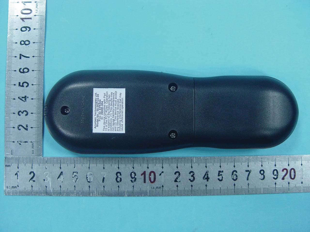
EPK504
Dec 02, 2010Acumen FDC 504 Tx Only
Equipment Class
DSC - Part 15 Security/Remote Control Transmitter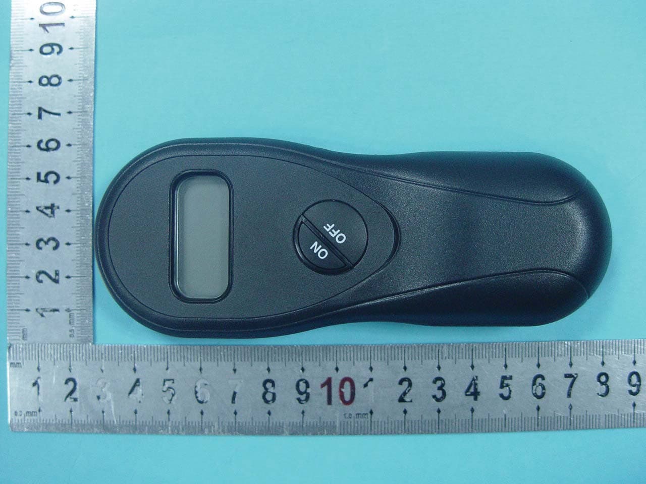
EPK502
Dec 02, 2010Acumen FDC 502 Tx Only
Equipment Class
DSC - Part 15 Security/Remote Control Transmitter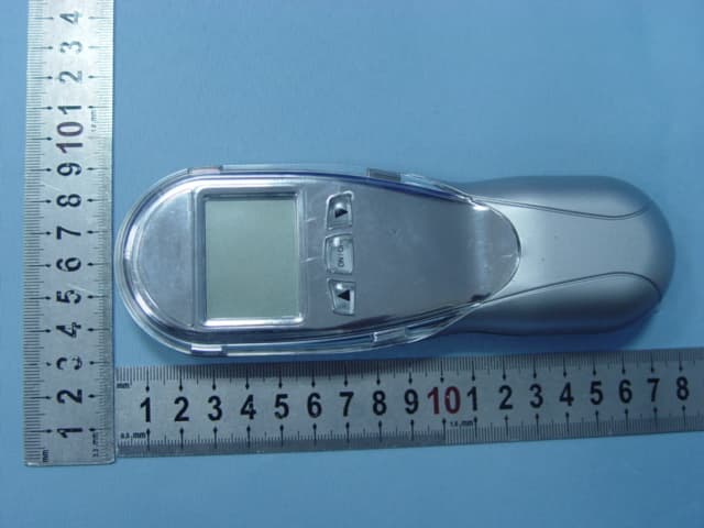
EPKEON0304
Nov 19, 2007EON 03/04
Equipment Class
DSC - Part 15 Security/Remote Control Transmitter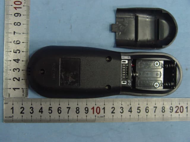
EPK001105A
Oct 23, 2006Johnson Gas RF Model H Version
Equipment Class
DSC - Part 15 Security/Remote Control Transmitter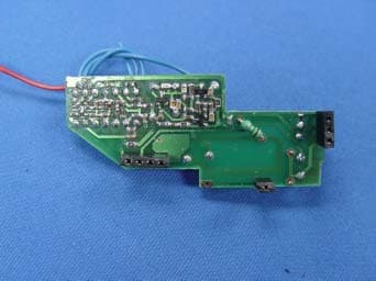
EPK001106A
Sep 26, 2006Fireplace Remote Control
Equipment Class
DSC - Part 15 Security/Remote Control Transmitter